2022 NISSAN ARMADA display
[x] Cancel search: displayPage 132 of 604

2-38Instruments and controls
button for longer than 1 second.
The display is updated every 30 seconds.
At about the first 1/3 mile (500 m) after a
reset, the display shows “——”.
8. Intelligent Cruise Control (ICC)
system
This mode shows the operating condition
for the Intelligent Cruise Control (ICC)
system. (See “Intelligent Cruise Control
(ICC)” (P.5-74).)
NOTE:
If the ICC system is in a standby state,
this screen is automatically displayed.
9. Driving aids (if so equipped)
The driving aids mode shows the operat-
ing condition for the following systems, if
the vehicle is equipped with them.
. Automatic Emergency Braking (AEB)
with pedestrian detection system
. Intelligent Forward Collision Warning
(I-FCW)
. Lane Departure Warning (LDW)
. Intelligent Lane Intervention (I-LI)
. Blind Spot Warning (BSW)
. Intelligent Blind Spot Intervention (I-
BSI)
For more details, see “Automatic Emer-
gency Braking (AEB) with pedestrian de-
tection system” (P.5-96), “Intelligent Forward Collision Warning (I-FCW)” (P.5-
106), “Lane Departure Warning (LDW)” (P.5-
26), “Intelligent Lane Intervention (I-LI)”
(P.5-31), “Blind Spot Warning (BSW)” (P.5-
38) or “Intelligent Blind Spot Intervention
(I-BSI)” (P.5-46).
10. Tire pressures
The tire pressure mode shows the pres-
sure of all four tires while the vehicle is
driven.
When the “Tire Pressure Low Add Air”
warning appears, the display can be
switched to the tire pressure mode by
pushing the left or right side of the
button.
The tire pressure unit can be changed
using the “TPMS Setting” menu displayed
in the vehicle information display. (See
“TPMS Setting” (P.2-23).)
NOTE:
After the ignition switch is placed in the
ON position, it may take a period of time
for the tire pressure to be displayed
while the vehicle is driven. Depending
on the radio wave circumstance, tire
pressure may not correctly be dis-
played.WAC0225X
11. Auxiliary gauges
The auxiliary gauges consist of the bat-
tery voltage gauge and the engine oil
pressure gauge.
The engine oil pressure gauge indicates
current engine oil pressure. (See “Engine
oil pressure gauge” (P.2-9).)
The battery voltage gauge indicates cur-
rent battery voltage. (See “Voltmeter” (P.2-
10).)
Page 133 of 604
WAC0226X
CLOCK AND OUTSIDE AIR TEM-
PERATURE
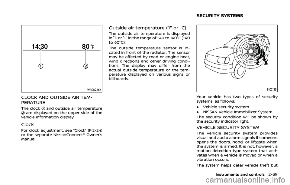
The clockand outside air temperatureare displayed on the upper side of the
vehicle information display.
Clock
For clock adjustment, see “Clock” (P.2-24)
or the separate NissanConnect® Owner’s
Manual.
Outside air temperature (°F or °C)
The outside air temperature is displayed
in °F or °C in the range of −40 to 140°F (−40
to 60°C).
The outside temperature sensor is lo-
cated in front of the radiator. The sensor
may be affected by road or engine heat,
wind directions and other driving condi-
tions. The display may differ from the
actual outside temperature or the tem-
perature displayed on various signs or
billboards.
SIC2133
Your vehicle has two types of security
systems, as follows:
. Vehicle security system
. NISSAN Vehicle Immobilizer System
The security condition will be shown by
the security indicator light.
VEHICLE SECURITY SYSTEM
The vehicle security system provides
visual and audio alarm signals if someone
opens the doors, hood, or liftgate when
the system is armed. It is not, however, a
motion detection type system that acti-
vates when a vehicle is moved or when a
vibration occurs.
The system helps deter vehicle theft but
Instruments and controls2-39
SECURITY SYSTEMS
Page 147 of 604
SIC4378
INSTRUMENT BRIGHTNESS CON-
TROL
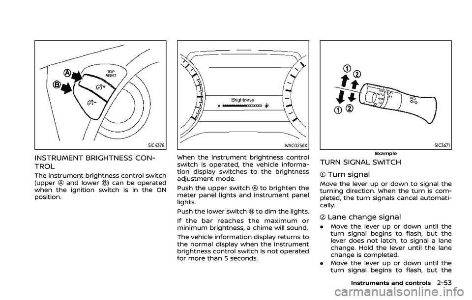
The instrument brightness control switch
(upperand lower) can be operated
when the ignition switch is in the ON
position.
WAC0256X
When the instrument brightness control
switch is operated, the vehicle informa-
tion display switches to the brightness
adjustment mode.
Push the upper switch
to brighten the
meter panel lights and instrument panel
lights.
Push the lower switch
to dim the lights.
If the bar reaches the maximum or
minimum brightness, a chime will sound.
The vehicle information display returns to
the normal display when the instrument
brightness control switch is not operated
for more than 5 seconds.
SIC3671
Example
TURN SIGNAL SWITCH
Turn signal
Move the lever up or down to signal the
turning direction. When the turn is com-
pleted, the turn signals cancel automati-
cally.
Lane change signal
. Move the lever up or down until the
turn signal begins to flash, but the
lever does not latch, to signal a lane
change. Hold the lever until the lane
change is completed.
. Move the lever up or down until the
turn signal begins to flash, but the
Instruments and controls2-53
Page 152 of 604
2-58Instruments and controls
4. When the vehicle’s interior is warmedor cooled, or before you leave the
vehicle, be sure to turn off the climate
controlled seats. To turn off the cli-
mate controlled seats, push the
switch until the indicator light turns
off.
To check the air filters for the climate
controlled seat, it is recommended
you visit a NISSAN dealer.
WARNING
Do not use or allow occupants to use
the climate controlled seats if you or
the occupants cannot monitor seat
temperatures or have an inability to
feel pain in those body parts in
contact with the seat. Use of the
climate controlled seats by such
people could result in serious injury.
CAUTION
.The battery could run down if the
climate controlled seat is oper-
ated while the engine is not run-
ning. .
Do not use the climate controlled
seat for extended periods or
when no one is using the seat.
. Do not put anything on the seat
which insulates heat, such as a
blanket, cushion, seat cover, etc.
Otherwise, the seat may become
overheated.
. Do not place anything hard or
heavy on the seat or pierce it with
a pin or similar object. This may
result in damage to the climate
controlled seat.
. Any liquid spilled on the seat
should be removed immediately
with a dry cloth.
. The climate controlled seat has
an air filter. Do not operate cli-
mate controlled seat without an
air filter. This may result in da-
mage to the system.
. When cleaning the seat, never use
gasoline, thinner, or any similar
materials.
. If any malfunctions are found or
the climate controlled seat does
not operate, turn the switch off
and have the system checked. It
is recommended you visit a
NISSAN dealer for this service.
SSD0956
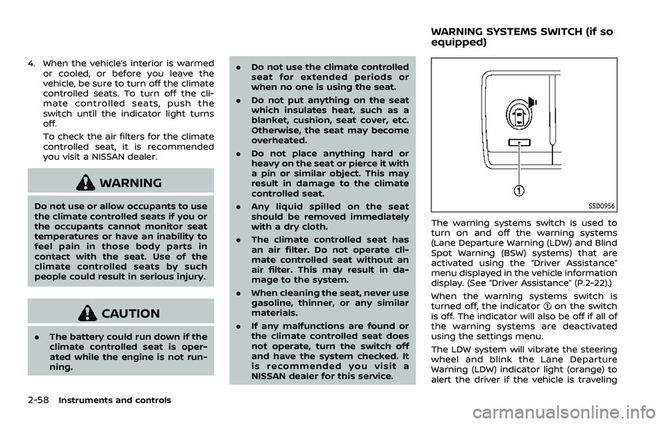
The warning systems switch is used to
turn on and off the warning systems
(Lane Departure Warning (LDW) and Blind
Spot Warning (BSW) systems) that are
activated using the “Driver Assistance”
menu displayed in the vehicle information
display. (See “Driver Assistance” (P.2-22).)
When the warning systems switch is
turned off, the indicator
on the switch
is off. The indicator will also be off if all of
the warning systems are deactivated
using the settings menu.
The LDW system will vibrate the steering
wheel and blink the Lane Departure
Warning (LDW) indicator light (orange) to
alert the driver if the vehicle is traveling
WARNING SYSTEMS SWITCH (if so
equipped)
Page 155 of 604
The Rear Door Alert system functions
under certain conditions to indicate there
may be an object or passenger in the rear
seat(s). Check the seat(s) before exiting
the vehicle.
The Rear Door Alert system is initially
enabled. The driver can disable the sys-
tem using the vehicle information display.
(See “Vehicle settings” (P.2-24).)
When the system is enabled:
.The system is activated when a rear
door is opened and closed. When the
vehicle is started and the system is
activated, a visual message appears in
the vehicle information display. (See
“42. Rear Door Alert is activated” (P.2-
34).)
. If a rear door is opened and closed but
the vehicle is not driven, the system
will not be activated. A rear door must
be opened and closed and the car
driven for the system to activate.
. The time interval to activate the
system between when the rear door
is opened and closed and the vehicle
is started is about 10 minutes. A longer
interval does not indicate a malfunc-
tion. When the Rear Door Alert system is
activated:
.
When the driver puts the vehicle in the
P (Park) position, a notification mes-
sage appears in the vehicle informa-
tion display with the options to
“Dismiss Message” or “Disable Alert” if
desired.
— Select “Disable Alert” to temporarily
disable for that stop.
— No selection or ‘Dismiss Message” will keep the alert enabled for that
stop.
. If the alert is enabled when a driver
exits the vehicle, a message will ap-
pear in the vehicle information display
that states “Check Rear Seat for All
Articles.”
If “Horn & Alert” setting is selected:
— An audible horn sound will occur
after a short time unless a rear
door is opened and closed within a
short time to deactivate the alert.
— If the doors are locked before the alert is deactivated by opening a
rear door, the horn will sound.
— If the liftgate is opened before a rear door is opened, the horn will be
delayed until after the liftgate is
closed. NOTE:
If “Alert Only” setting is selected, the
message alert will still be shown in the
vehicle information display but the horn
will not sound.
WARNING
.
If the driver selects “Disable
Alert”, no audible alert will be
provided regardless of rear door
open/close status.
. There may be times when there is
an object or passenger in the rear
seat(s) but the audible alert does
not sound. For example, this may
occur if rear seat passengers
enter or exit the vehicle during a
trip.
. The system does not directly
detect objects or passengers in
the rear seat(s). Instead, it can
detect when a rear door is
opened and closed, indicating
that there may be something in
the rear seat(s).
NOTE:
There may be times when the horn
sounds but there are no objects or
passengers in the rear seat(s).
Instruments and controls2-61
REAR DOOR ALERT
Page 182 of 604

2-88Instruments and controls
stop and reverse features as re-
quired by federal safety stan-
dards. (These standards became
effective for opener models man-
ufactured after April 1, 1982). A
garage door opener which cannot
detect an object in the path of a
closing garage door and then
automatically stop and reverse,
does not meet current federal
safety standards. Using a garage
door opener without these fea-
tures increases the risk of serious
injury or death.
. During the programming proce-
dure your garage door or security
gate will open and close (if the
transmitter is within range). Make
sure that people or objects are
clear of the garage door, gate,
etc. that you are programming.
. Your vehicle’s engine should be
turned off while programming
the HomeLink® Universal Trans-
ceiver. Do not breathe exhaust
gases; they contain colorless
and odorless carbon monoxide.
Carbon monoxide is dangerous. It
can cause unconsciousness or
death. NOTE:
If your vehicle is equipped with Intelli-
gent Rear View Mirror, you may have to
complete additional programming to
enable Two-Way Communication. The
mirror can provide the status of your
garage door (open/close).
PROGRAMMING HomeLink®
The following steps show generic instruc-
tions how to program a HomeLink®
button. If you have any questions or are
having difficulty programming your
HomeLink® buttons, refer to the
HomeLink® web site at: www.homelink.
com/nissan or call 1-800-355-3515.
NOTE:
It is also recommended that a new
battery be placed in the hand-held
transmitter of the device being pro-
grammed to HomeLink® for quicker
programming and accurate transmis-
sion of the radio-frequency.
WAC0378X
HomeLink® buttons (1-3)Indicator light (appears above each
HomeLink® button)
Status display (where the current condi-
tion of the HomeLink® is displayed)
Page 183 of 604

WAC0381X
1. Press and release the HomeLink®button that you would like to pro-
gram. The HomeLink® indicator light
will flash in orange slowly and “TRAIN-
ING” is displayed on the lower right of
the mirror (if not, refer to “Clearing the
programmed information” (P.2-92).).
2. Position the hand-held transmitter (garage door opener remote) 1-3
inches (2-8 cm) away from the
HomeLink® button that you would
light to program.
NOTE:
Some hand-held transmitter (gar-
age door opener remotes) may ac-
tually train better at a distance of 6- 12 inches (15-20 cm). Keep this in
mind if you have difficulty with the
programming process.
3. While the HomeLink® indicator light is flashing in orange, press and hold the
hand-held transmitter button. Con-
tinue pressing the hand-held trans-
mitter button until the HomeLink®
indicator light changes from orange
to green and “TRAINED” is displayed on
the lower right of the mirror. You may
now release the hand-held transmit-
ter button.
NOTE:
Some devices to be programmed
may require you to replace the Step
3 with the cycling procedure noted
in “Programming HomeLink® for Ca-
nadian customers and gate open-
ers” (P.2-91).
4. Wait until your garage door has
stopped moving before completing
the next steps.
5. Press the HomeLink® button and ob- serve the indicator light.
.If the indicator light remains con-stant green, your device should
operate when the HomeLink® but-
ton is pressed. At this point, if your
device operates, programming is
complete.
.If the indicator light rapidly flashesin green, firmly press, hold for two
seconds and release the
HomeLink® button up to three
times to complete the program-
ming process. Do not press the
HomeLink® button rapidly. At this
point if your device operates, pro-
gramming is complete. If the device
does not operate or operates but
no door status indicator with Two-
Way Communication
*1, continue
with the next step of the program-
ming instructions.
6. At the garage door opener motor (security gate motor, etc.), locate the
“Learn” or “Set” button. This can usual-
ly be found where the hanging anten-
na wire is attached to the motor-head
unit (see the device’s manual to iden-
tify this button.). The name and color
of the button may vary by manufac-
turer.
NOTE:
A ladder and/or second person may
simplify the following steps. Do not
stand on your vehicle to perform the
next steps.
Instruments and controls2-89
Page 185 of 604
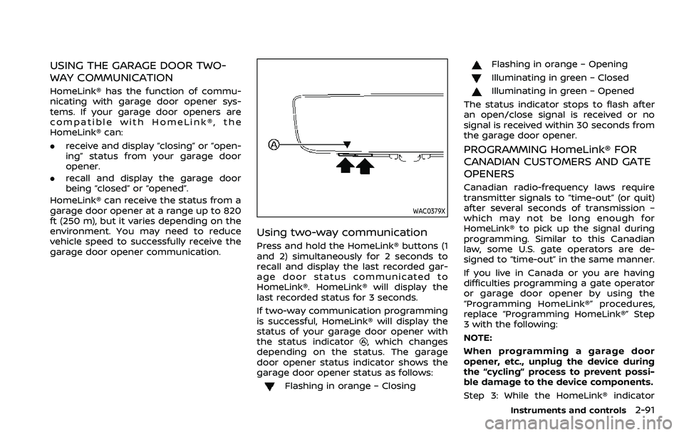
USING THE GARAGE DOOR TWO-
WAY COMMUNICATION
HomeLink® has the function of commu-
nicating with garage door opener sys-
tems. If your garage door openers are
compatible with HomeLink®, the
HomeLink® can:
.receive and display “closing” or “open-
ing” status from your garage door
opener.
. recall and display the garage door
being “closed” or “opened”.
HomeLink® can receive the status from a
garage door opener at a range up to 820
ft (250 m), but it varies depending on the
environment. You may need to reduce
vehicle speed to successfully receive the
garage door opener communication.
WAC0379X
Using two-way communication
Press and hold the HomeLink® buttons (1
and 2) simultaneously for 2 seconds to
recall and display the last recorded gar-
age door status communicated to
HomeLink®. HomeLink® will display the
last recorded status for 3 seconds.
If two-way communication programming
is successful, HomeLink® will display the
status of your garage door opener with
the status indicator
, which changes
depending on the status. The garage
door opener status indicator shows the
garage door opener status as follows:
Flashing in orange – Closing
Flashing in orange – Opening
Illuminating in green – Closed
Illuminating in green – Opened
The status indicator stops to flash after
an open/close signal is received or no
signal is received within 30 seconds from
the garage door opener.
PROGRAMMING HomeLink® FOR
CANADIAN CUSTOMERS AND GATE
OPENERS
Canadian radio-frequency laws require
transmitter signals to “time-out” (or quit)
after several seconds of transmission –
which may not be long enough for
HomeLink® to pick up the signal during
programming. Similar to this Canadian
law, some U.S. gate operators are de-
signed to “time-out” in the same manner.
If you live in Canada or you are having
difficulties programming a gate operator
or garage door opener by using the
“Programming HomeLink®” procedures,
replace “Programming HomeLink®” Step
3 with the following:
NOTE:
When programming a garage door
opener, etc., unplug the device during
the “cycling” process to prevent possi-
ble damage to the device components.
Step 3: While the HomeLink® indicator
Instruments and controls2-91