2022 NISSAN ARMADA height
[x] Cancel search: heightPage 361 of 604
2. Select “Blind Spot” and push the OK.
3. Select “Intervention (BSI)” and pushthe OK.
4. Push the Dynamic driver assistance switch to turn the system on or off.
The dynamic driver assistance switch
is
used for the I-LI and I-BSI systems.
When the dynamic driver assistance
switch
is pushed, the I-LI system will
also turn on or off simultaneously. The I-
BSI system can be individually set to on or
off on the vehicle information display.
If the system is set to off, the system will
not turn on even if the dynamic driver
assistance switch
is pushed to on.
I-BSI SYSTEM LIMITATIONS
WARNING
Listed below are the system limita-
tions for the I-BSI system. Failure to
operate the vehicle in accordance
with these system limitations could
result in serious injury or death.
. The I-BSI system cannot detect all
vehicles under all conditions.
. The radar sensors may not be
able to detect and activate I-BSI
when certain objects are present such as:
— Pedestrians, bicycles, animals.
— Vehicles such as motorcycles,
low height vehicles, or high
ground clearance vehicles.
— Vehicles remaining in the de- tection zone when you accel-
erate from a stop.
— Oncoming vehicles.
— A vehicle merging into an adjacent lane at a speed ap-
proximately the same as your
vehicle.
— A vehicle approaching rapidly from behind.
— A vehicle which your vehicle overtakes rapidly.
— A vehicle that passes through the detection zone quickly.
. The radar sensor’s detection zone
is designed based on a standard
lane width. When driving in a
wider lane, the radar sensors
may not detect vehicles in an
adjacent lane. When driving in a
narrow lane, the radar sensors
may detect vehicles driving two
lanes away. .
The radar sensors are designed
to ignore most stationary objects,
however objects such as guard-
rails, walls, foliage and parked
vehicles may occasionally be de-
tected. This is a normal operation
condition.
. The following conditions may re-
duce the ability of the radar to
detect other vehicles:
— Severe weather
— Road spray
— Ice/frost/dirt build-up on the
vehicle
. Do not attach stickers (including
transparent material), install ac-
cessories or apply additional
paint near the radar sensors.
These conditions may reduce the
ability of the radar to detect other
vehicles.
. The camera may not detect lane
markers in the following situa-
tions and the I-BSI system may
not operate properly.
— On roads where there are
multiple parallel lane markers;
lane markers that are faded or
not painted clearly; yellow
painted lane markers; non-
Starting and driving5-49
Page 413 of 604

— When your vehicle or the ve-hicle or pedestrian ahead
moves quickly or significantly
such that the system cannot
detect and react in time (for
example, pedestrian moving
quickly toward the vehicle at
close range, vehicle cutting in,
changing lanes, making a
turn, steering abruptly, sud-
den acceleration or decelera-
tion).
— When the vehicle or pedes- trian is offset from the vehi-
cle’s forward path.
— If the speed difference be- tween the two vehicles is
small.
— The pedestrian’s profile is par- tially obscured or unidentifi-
able; for example, due to
transporting luggage, push-
ing a stroller, wearing bulky
or very loose-fitting clothing
or accessories, or being in a
unique posture (such as rais-
ing hands).
— There is poor contrast of a person to the background,
such as having clothing color
or pattern which is similar to the background.
— For approximately 15 seconds after starting the engine
— If the vehicle ahead has a unique or unusual shape, ex-
tremely low or high clearance
heights, or unusual cargo
loading or is narrow (for ex-
ample, a motorcycle).
— When the vehicle or pedes- trian is located near a traffic
sign, a reflective area (for ex-
ample, water on road), or is in
a shadow.
— When multiple pedestrians are grouped together.
— When the view of the pedes- trian is obscured by a vehicle
or other object.
— While towing a trailer or other vehicle.
. The system performance may be
degraded in the following condi-
tions:
— The vehicle is driven on a
slippery road.
— The vehicle is driven on a slope. — Excessively heavy baggage is
loaded in the rear seat or the
cargo area of your vehicle.
. The system is designed to auto-
matically check the sensor (radar
and camera)’s functionality, with-
in certain limitations. The system
may not detect some forms of
obstruction of the sensor area
such as ice, snow or stickers, for
example. In these cases, the sys-
tem may not be able to warn the
driver properly. Be sure that you
check, clean and clear sensor
areas regularly.
. In some road and traffic condi-
tions, the AEB with pedestrian
detection system may unexpect-
edly apply partial braking. When
acceleration is necessary, de-
press the accelerator pedal to
override the system.
. The AEB with pedestrian detec-
tion system may operate when a
pattern, object, shadow or lights
are detected that are similar to
the outline of vehicles or pedes-
trians, or if they are the same size
and position as a vehicle or mo-
torcycle’s tail lights.
Starting and driving5-101
Page 433 of 604
the same obstacle.
. The automatic brake control can
only operate for a short period of
time. Therefore, the driver must
depress the brake pedal.
. In the following situations, the
RAB system may not operate
properly or may not function
sufficiently:
— The vehicle is driven in bad
weather (rain, fog, snow, etc.).
— The vehicle is driven on a steep hill.
— The vehicle’s posture is chan- ged (e.g., when driving over a
bump).
— The vehicle is driven on a slippery road.
— The vehicle is turned sharply by turning the steering wheel
fully.
— Snow chains are used.
— Wheels or tires other than NISSAN recommended are
used.
— The brakes are cold at low ambient temperatures or im-
mediately after driving has
started. — The braking force becomes
poor due to wet brakes after
driving through a puddle or
washing the vehicle.
. Turn the RAB system off in the
following conditions to prevent
the occurrence of an unexpected
accident resulting from sudden
system operation:
— The vehicle is towed.
— The vehicle is carried on a
flatbed truck.
— The vehicle is on the chassis dynamometer.
— The vehicle drives on an un- even road surface.
— Suspension parts other than those designated as genuine
parts are used. (If the vehicle
height or the vehicle body
inclination is changed, the
system may not detect an
obstacle correctly.)
. When towing a trailer or other
vehicle, turn the RAB system off
to prevent the occurrence of an
unexpected accident resulting
from sudden system operation.
(See “RAB system operation” (P.5-
118).) .
Excessive noise (e.g., audio sys-
tem volume, an open vehicle win-
dow) will interfere with the chime
sound, and it may not be heard.
SYSTEM MALFUNCTION
If the RAB system malfunctions, it will be
turned off automatically, the RAB system
warning light will illuminate, and the
“System fault See Owner’s Manual” warn-
ing message will appear in the vehicle
information display.
Action to take
If the warning light illuminates, park the
vehicle in a safe location, turn the engine
off, and restart the engine. If the warning
light continues to illuminate, have the
RAB system checked. It is recommended
that you visit a NISSAN dealer for this
service.
NOTE:
If the RAB system cannot be operated
temporarily, the RAB system warning
light blinks.
Starting and driving5-121
Page 509 of 604
It is recommended you visit a NISSAN
dealer if checking or replacement is
required.If the brakes do not operate properly,
have the brakes checked. It is recom-
mended that you visit a NISSAN dealer for
this service.
SELF-ADJUSTING BRAKES
Your vehicle is equipped with self-adjust-
ing brakes.
The disc-type brakes self-adjust every
time the brake pedal is applied.
WARNING
Have your brake system checked if
the brake pedal height does not
return to normal. It is recommended
you visit a NISSAN dealer for this
service.
BRAKE PAD WEAR WARNING
The disc brake pads have audible wear
warnings. When a brake pad requires
replacement, it will make a high pitched
scraping sound when the vehicle is in
motion. This scraping sound will first
occur only when the brake pedal is
depressed. After more wear of the brake
pad, the sound will always be heard even
if the brake pedal is not depressed. Have
the brakes checked as soon as possible if
the wear warning sound is heard.Under some driving or climate conditions,
occasional brake squeak, squeal or other
noise may be heard. Occasional brake
noise during light to moderate stops is
normal and does not affect the function
or performance of the brake system.
Proper brake inspection intervals
should be followed.
For additional infor-
mation, see the maintenance schedule
shown in the “9. Maintenance and sche-
dules” section.
BRAKE BOOSTER
Check the brake booster function as
follows:
1. With the engine off, depress and release the foot brake pedal more
than 20 times. When the foot brake
pedal movement (distance of travel)
remains the same from one pedal
application to the next, continue on
to the next step.
2. While depressing the foot brake pedal, start the engine.
3. With the foot brake pedal depressed, stop the engine. Keep the pedal de-
pressed for about 30 seconds.
4. Run the engine for 1 minute without depressing the foot brake pedal, then
turn it off. Depress the foot brake
pedal several times. The pedal travel
distance will decrease gradually with
Do-it-yourself8-17
REAR WINDOW WIPER BLADES BRAKES
Page 525 of 604
SDI1606
Example
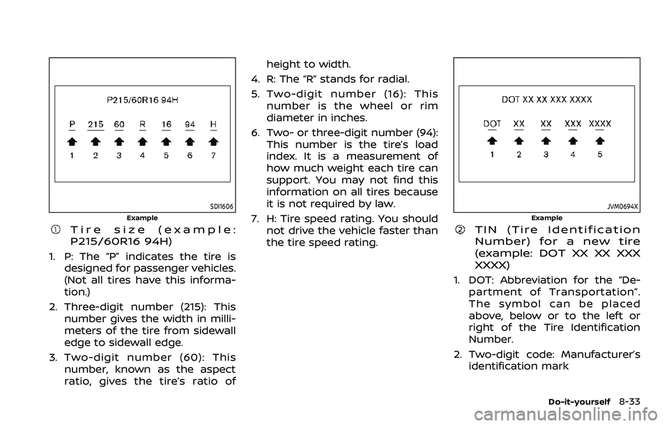
Tire size (example:
P215/60R16 94H)
1. P: The “P” indicates the tire isdesigned for passenger vehicles.
(Not all tires have this informa-
tion.)
2. Three-digit number (215): This number gives the width in milli-
meters of the tire from sidewall
edge to sidewall edge.
3. Two-digit number (60): This number, known as the aspect
ratio, gives the tire’s ratio of height to width.
4. R: The “R” stands for radial.
5. Two-digit number (16): This number is the wheel or rim
diameter in inches.
6. Two- or three-digit number (94): This number is the tire’s load
index. It is a measurement of
how much weight each tire can
support. You may not find this
information on all tires because
it is not required by law.
7. H: Tire speed rating. You should not drive the vehicle faster than
the tire speed rating.
JVM0694X
Example
TIN (Tire Identification
Number) for a new tire
(example: DOT XX XX XXX
XXXX)
1. DOT: Abbreviation for the “De-
partment of Transportation”.
The symbol can be placed
above, below or to the left or
right of the Tire Identification
Number.
2. Two-digit code: Manufacturer’s identification mark
Do-it-yourself8-33
Page 529 of 604
SDI1663
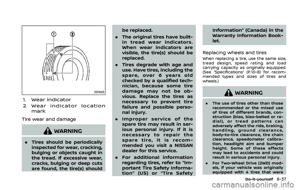
1. Wear indicator
2. Wear indicator locationmark
Tire wear and damage
WARNING
.Tires should be periodically
inspected for wear, cracking,
bulging or objects caught in
the tread. If excessive wear,
cracks, bulging or deep cuts
are found, the tire(s) should be replaced.
. The original tires have built-
in tread wear indicators.
When wear indicators are
visible, the tire(s) should be
replaced.
. Tires degrade with age and
use. Have tires, including the
spare, over 6 years old
checked by a qualified tech-
nician, because some tire
damage may not be ob-
vious. Replace the tires as
necessary to prevent tire
failure and possible perso-
nal injury.
. Improper service of the
spare tire may result in ser-
ious personal injury. If it is
necessary to repair the
spare tire, it is recom-
mended you visit a NISSAN
dealer for this service.
. For additional information
regarding tires, refer to “Im-
portant Tire Safety Informa-
tion” (US) or “Tire Safety Information” (Canada) in the
Warranty Information Book-
let.
Replacing wheels and tires
When replacing a tire, use the same size,
tread design, speed rating and load
carrying capacity as originally equipped.
(See “Specifications” (P.10-8) for recom-
mended types and sizes of tires and
wheels.)
WARNING
. The use of tires other than those
recommended or the mixed use
of tires of different brands, con-
struction (bias, bias-belted or ra-
dial), or tread patterns can
adversely affect the ride, braking,
handling, ground clearance,
body-to-tire clearance, tire chain
clearance, speedometer calibra-
tion, headlight aim and bumper
height. Some of these effects
may lead to accidents and could
result in serious personal injury.
. For Two-Wheel Drive (2WD) mod-
els, if your vehicle was originally
equipped with 4 tires that were
Do-it-yourself8-37
Page 564 of 604
10-10Technical and consumer information
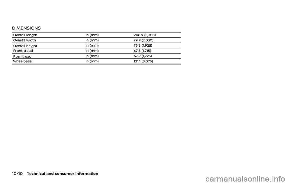
DIMENSIONS
Overall lengthin (mm)208.9 (5,305)
Overall width in (mm)79.9 (2,030)
Overall height in (mm)
75.8 (1,925)
Front tread in (mm)67.5 (1,715)
Rear tread in (mm)
67.9 (1,725)
Wheelbase in (mm)121.1 (3,075)
Page 580 of 604
10-26Technical and consumer information
with the surge brake, hitch or trailer
manufacturer to determine if and how
this can be done.
Follow the instructions provided by the
manufacturer for installing and using the
weight-distributing hitch system.
General set-up instructions are as follows:
1. Park unloaded vehicle on a level sur-face. With the ignition switch in the ON
position and the doors closed, allow
the vehicle to stand for several min-
utes so that it can level.
2. Measure the height of a reference point on the front and rear bumpers
at the center of the vehicle.
3. Attach the trailer to the vehicle and adjust the hitch equalizers so that the
front bumper height is within 0 - .5
inches (0 - 13 mm) of the reference
height measured in step 2. The rear
bumper should be no higher than the
reference height measured in step 2.
WARNING
Properly adjust the weight distribut-
ing hitch so the rear of the bumper is
no higher than the measured refer-
ence height when the trailer is at-
tached. If the rear bumper is higher than the measured reference height
when loaded, the vehicle may handle
unpredictably which could cause a
loss of vehicle control and cause
serious personal injury or property
damage.
Sway control device
Sudden maneuvers, wind gusts and buf-
feting caused by other vehicles can affect
trailer handling. Sway control devices
may be used to help control these affects.
If you choose to use one, contact a
reputable trailer hitch supplier to make
sure the sway control device will work
with the vehicle, hitch, trailer and the
trailer’s brake system. Follow the instruc-
tions provided by the manufacturer for
installing and using the sway control
device.
Class I hitch
Class I trailer hitch equipment (receiver,
ball mount and hitch ball) can be used to
tow trailers of a maximum weight of
2,000 lb (907 kg).
Class II hitch
Class II trailer hitch equipment (receiver,
ball mount and hitch ball) can be used to
tow trailers of a maximum weight of
3,500 lb (1,588 kg).
Class III hitch
Class III trailer hitch equipment (receiver,
ball mount and hitch ball) can be used to
tow trailers of a maximum weight of
5,000 lb (2,267 kg).
Class IV hitch
Class IV trailer hitch equipment (receiver,
ball mount and hitch ball) can be used to
tow trailers of a maximum weight of
10,000 lb (4,545 kg). A weight distributing
hitch should be used to tow trailers that
weigh over 5,000 lb (2,267 kg).
Your vehicle may be equipped with Class
IV trailer hitch equipment that has a
10,000 lb (4,545 kg) maximum weight
rating, but your vehicle is only capable of
towing the maximum trailer weights
shown in the “Towing Load/Specification”
chart earlier in this section.
CAUTION
.
Do not use axle-mounted hitches.