2022 NISSAN ARMADA charging
[x] Cancel search: chargingPage 13 of 604

WAA0287X
1. Cargo light (P.2-83)
2. Cup holders (3rd row seat) (P.2-70)
3. Rear ventilators (P.4-36)
4. Coat hooks (P.2-73)
5. Rear personal lights (P.2-81)
6. Door armrest— Power window controls (P.2-75) — Power door lock switch (P.3-5)
— Outside mirror remote control switch
(driver’s side) (P.3-38)
7. Memory seat switch (if so equipped) (P.3-40)
8. Sun visors (P.3-29)
9. Map lights (P.2-81) 10. Moonroof switch (if so equipped) (P.2-78)
11. Emergency Call (SOS) button (if so
equipped) (P.2-67)
12. Sunglasses holder (P.2-71)
13. Inside mirror (P.3-30) — Intelligent Rear View Mirror (if so
equipped) (P.3-31)
— HomeLink® universal transceiver (if so
equipped) (P.2-83, P.2-87)
14. Cargo area — Power outlet (P.2-62)
— Cargo floor box (P.2-74)
— Luggage hooks (P.2-73)
— Jacking tools (P.6-5)
15. Rear console box (if so equipped) (P.2-72)
— Cup holders (2nd row seat) (P.2-69)
— Pocket (P.2-72)
16. Cup holders (2nd row seat) (if so equipped) (P.2-69)
17. Rear Seat Infotainment (RSI) system (if so equipped) (P.4-45)
18. Console box (P.2-72) — Power outlet (P.2-62)
— USB charging connector (P.2-64)
— Rear Media Interface
— Rear automatic air conditioning sys-
tem (if so equipped) (P.4-40)
19. Front cup holders (P.2-69)
Illustrated table of contents0-5
PASSENGER COMPARTMENT
Page 96 of 604
TOW mode switch ..................................................................... 2-59
Vehicle Dynamic Control (VDC) OFF switch ......... 2-60
Trailer Brake Controller Unit (TBCU) (if
so equipped) ........................................................................\
.......... 2-60
Rear door alert ........................................................................\
.... 2-61
Power outlet ........................................................................\
.......... 2-62USB (Universal Serial Bus)
charging connector .......................................................... 2-64
Wireless charger (if so equipped) ........................... 2-65
Emergency Call (SOS) button (if
so equipped) ........................................................................\
.......... 2-67
Emergency support .......................................................... 2-67
Storage ........................................................................\
...................... 2-69 Cup holders ........................................................................\
..... 2-69
Sunglasses holder .............................................................. 2-71
Glove box ........................................................................\
........... 2-71
Console box ........................................................................\
..... 2-72
Coat hooks ........................................................................\
....... 2-73
Luggage hooks ..................................................................... 2-73
Cargo floor box .................................................................... 2-74
Roof rack (if so equipped) ............................................ 2-74
Windows ........................................................................\
.................... 2-75 Power windows .................................................................... 2-75
Moonroof (if so equipped) .................................................. 2-78
Power moonroof ................................................................. 2-78
Welcome light (if so equipped) ....................................... 2-80 Battery saver system ..................................................... 2-80 Interior lights ........................................................................\
........ 2-81
Interior light switch ........................................................ 2-81
Console light ........................................................................\
2-82
Map lights ........................................................................\
....... 2-82
Rear personal lights ....................................................... 2-82
Vanity mirror lights ................................................................. 2-83
Cargo light ........................................................................\
............. 2-83
HomeLink® Universal Transceiver (Type A) (if
so equipped) ........................................................................\
......... 2-83 Programming HomeLink® ......................................... 2-84
Programming HomeLink® for Canadian
customers and gate openers ................................. 2-85
Operating the HomeLink®
Universal Transceiver .................................................... 2-86
Programming troubleshooting ............................. 2-86
Clearing the programmed information .......... 2-86
Reprogramming a single
HomeLink® button ........................................................... 2-86
If your vehicle is stolen ................................................ 2-87
HomeLink® Universal Transceiver (Type B) (if
so equipped) ........................................................................\
......... 2-87
Programming HomeLink® ......................................... 2-88
Using the garage door
two-way communication ........................................... 2-91
Programming HomeLink® for Canadian
customers and gate openers ................................. 2-91
Operating the HomeLink®
Universal Transceiver .................................................... 2-92
Page 104 of 604
2-10Instruments and controls
the dipstick to check the oil level.
(See “Engine oil” (P.8-6).)
. If the gauge does not move with
the proper amount of engine oil,
have the vehicle checked. It is
recommended you visit a NISSAN
dealer for this service. Continued
vehicle operation in such a con-
dition could cause serious da-
mage to the engine.
WAC0220X
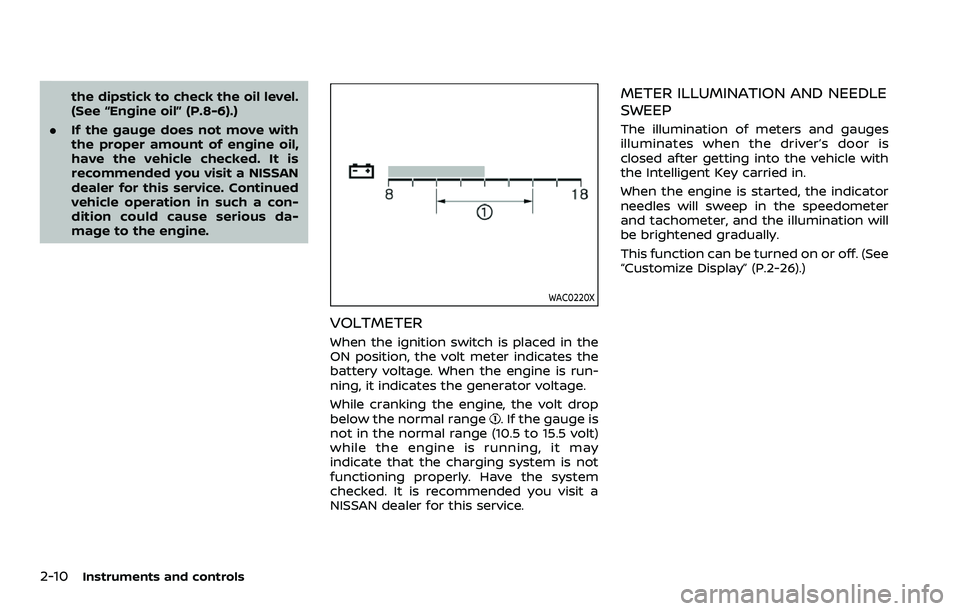
VOLTMETER
When the ignition switch is placed in the
ON position, the volt meter indicates the
battery voltage. When the engine is run-
ning, it indicates the generator voltage.
While cranking the engine, the volt drop
below the normal range
. If the gauge is
not in the normal range (10.5 to 15.5 volt)
while the engine is running, it may
indicate that the charging system is not
functioning properly. Have the system
checked. It is recommended you visit a
NISSAN dealer for this service.
METER ILLUMINATION AND NEEDLE
SWEEP
The illumination of meters and gauges
illuminates when the driver’s door is
closed after getting into the vehicle with
the Intelligent Key carried in.
When the engine is started, the indicator
needles will sweep in the speedometer
and tachometer, and the illumination will
be brightened gradually.
This function can be turned on or off. (See
“Customize Display” (P.2-26).)
Page 107 of 604
Low hydraulic pressure warning indica-
tor:
If the brake warning light illuminates
when the engine is running, or while
driving with the parking brake is released,
check the brake fluid level. If the brake
fluid level is sufficient, it may indicate low
hydraulic pressure in the brake booster. It
is recommended that you have the brake
system checked by a NISSAN dealer
promptly.
Anti-lock Braking System (ABS) warning
indicator:
When the parking brake is released and
the brake fluid level is sufficient, if both
the brake warning light and the Anti-lock
Braking System (ABS) warning light illu-
minate, it may indicate the ABS is not
functioning properly. Have the brake
system checked, and if necessary re-
paired. It is recommended you visit a
NISSAN dealer for this service. (See “Anti-
lock Braking System (ABS) warning light”
(P.2-15).)
WARNING
.Your brake system may not be
working properly if the warning
light is on. Driving could be dan-
gerous. If you judge it to be safe, drive carefully to the nearest
service station for repairs. Other-
wise, have your vehicle towed
because driving it could be dan-
gerous.
. Pressing the brake pedal with the
engine stopped and/or low brake
fluid level may increase your
stopping distance and braking
will require greater pedal effort
as well as pedal travel.
. If the brake fluid level is below the
minimum or MIN mark on the
brake fluid reservoir, do not drive
until the brake system has been
checked. It is recommended you
visit a NISSAN dealer for this
service.
Charge warning light
When the ignition switch is in the ON
position, the charge warning light illumi-
nates and then turns off.
If the light comes on while the engine is
running, it may indicate the charging
system is not functioning properly. Turn
the engine off and check the alternator
belt. If the belt is loose, broken, missing or
if the light remains on, have your vehicle
serviced immediately. It is recommended you visit a NISSAN dealer for this service.
CAUTION
Do not continue driving if the alter-
nator belt is loose, broken or miss-
ing.
Engine oil pressure warning
light
This light warns of low engine oil pres-
sure. If the light flickers or comes on
during normal driving, pull off the road in
a safe area, stop the engine immediately
and call a NISSAN dealer or other author-
ized repair shop.
The engine oil pressure warning light is
not designed to indicate a low oil level.
Use the dipstick to check the oil level.
(See “Engine oil” (P.8-6).)
CAUTION
Running the engine with the engine
oil pressure warning light on could
cause serious damage to the engine
almost immediately. Such damage is
not covered by warranty. Turn off the
engine as soon as it is safe to do so.
Instruments and controls2-13
Page 156 of 604
2-62Instruments and controls
(See “42. Rear Door Alert is activated” (P.2-
34).)
CAUTION
.Use power outlet with the engine
running to avoid discharging the
vehicle battery.
. Avoid using power outlet when
the air conditioner, headlights or
rear window defroster is on.
. Before inserting or disconnecting
a plug, be sure the electrical
accessory being used is turned
OFF.
. When not in use, be sure to close
the cap. Do not allow water or any
liquid to contact the outlet.
WAC0620XInstrument panel
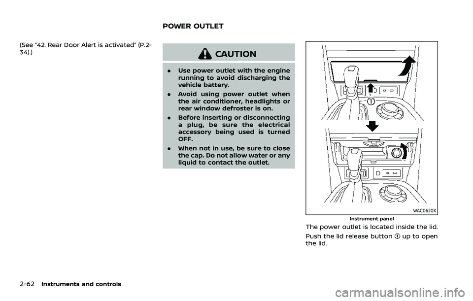
The power outlet is located inside the lid.
Push the lid release button
up to open
the lid.
POWER OUTLET
Page 158 of 604
2-64Instruments and controls
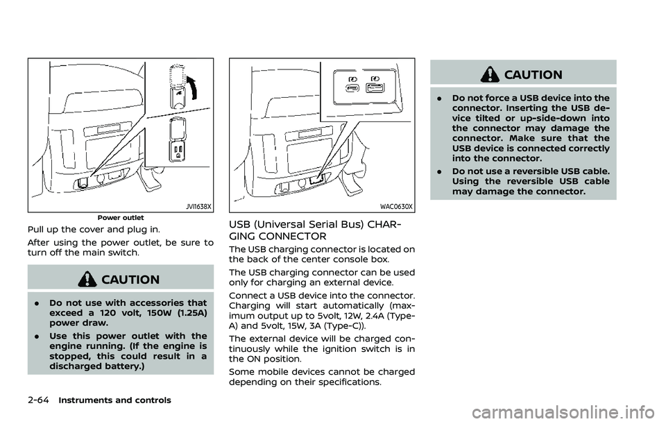
JVI1638X
Power outlet
Pull up the cover and plug in.
After using the power outlet, be sure to
turn off the main switch.
CAUTION
.Do not use with accessories that
exceed a 120 volt, 150W (1.25A)
power draw.
. Use this power outlet with the
engine running. (If the engine is
stopped, this could result in a
discharged battery.)
WAC0630X
USB (Universal Serial Bus) CHAR-
GING CONNECTOR
The USB charging connector is located on
the back of the center console box.
The USB charging connector can be used
only for charging an external device.
Connect a USB device into the connector.
Charging will start automatically (max-
imum output up to 5volt, 12W, 2.4A (Type-
A) and 5volt, 15W, 3A (Type-C)).
The external device will be charged con-
tinuously while the ignition switch is in
the ON position.
Some mobile devices cannot be charged
depending on their specifications.
CAUTION
.Do not force a USB device into the
connector. Inserting the USB de-
vice tilted or up-side-down into
the connector may damage the
connector. Make sure that the
USB device is connected correctly
into the connector.
. Do not use a reversible USB cable.
Using the reversible USB cable
may damage the connector.
Page 159 of 604

WAC0621X
1. Lid release button
2. Charging pad
3. Indicator
WIRELESS CHARGER (if so equipped)
The wireless charger is located inside the
lid. Push the lid release button up to open
the lid. Place the smartphone on the padof the wireless charger with screen face
up. Charging will start automatically. The
smartphone will be charged continuously
while the ignition switch is in the ON
position.
WARNING
.
Never put metallic materials be-
tween the wireless charger and a
smartphone.
. Those who use a pacemaker or
other medical equipment should
contact the electric medical
equipment manufacturer for the
possible influences before use.
. Never put cloth over the smart-
phone during charging process.
. Never charge a smartphone when
it is wet.
. Never put metallic materials or
small goods such as a cigarette
lighter, Intelligent Key or memory
drive.
CAUTION
.Do not put an RFID/NFC/credit
card between the wireless char-
ger and a smartphone. This could
cause data corruption in the card.
. Do not use the wireless charger
with dust accumulated or dirt on
the pad.
. Do not hit the surface of the
wireless charger.
. Do not spill liquid (water, drinks,
etc.) on the charging pad.
. Do not use grease, oil or alcohol
for cleaning charging pad.
Wireless charger Indicator
The indicatorwill illuminate in orange
when the charging process is started.
When the charging has completed, the
indicator illuminates in green.
If a malfunction occurs or the charging
process has stopped, the indicator will
blink in orange for 8 seconds then turn
off.
Instruments and controls2-65
Page 160 of 604

2-66Instruments and controls
Operation of the wireless charger
To use the wireless charger, it is neces-
sary to properly position the smartphone
on the charging pad with the screen
facing up. To maximize charging perfor-
mance, ensure the smartphone is fully
seated on the center of the charging pad
over the
logo. Because the location
of the power receiver may vary depend-
ing on the smartphone, you will need to
try and find the area that suits your
smartphone.
Because some smartphone cases or ac-
cessories may adversely affect charging,
remove them before wireless charging.
Turn off the vibration function of the
smartphone before wireless charging.
NOTE:
. Only a Qi compatible smartphone
can be used.
. The smartphone or the wireless
charger may be warmed during
charging process and the charging
may stop by the protection function
of the smartphone or the wireless
charger. This is not a malfunction. If
this occurs, restart charging after
the smartphone or the wireless
charger cooled down. The indicator
will blink in orange then turn off. .
The wireless charging process may
be stopped by the status of the
smartphone (battery temperature,
etc.).
. If a radio noise interference occurs
during charging process, put the
smartphone onto the center (logo) position of the wireless char-
ger.
. The wireless charging process will
stop during process of searching the
Intelligent Key.
. The wireless charging process will
not be started when a USB (Univer-
sal Serial Bus) cable is connected to
the smartphone. The indicator may
illuminate in orange or blink if the
smartphone is put on the wireless
charger with a USB cable connected.
However, charging is not performed.
. Depending on the type of the smart-
phone, the indicator may remain
illuminated in orange even when
the charging process has been com-
pleted.
FCC ID: BEJWC500MNM
IC: 2703H-WC500MNM
This device complies with part 15 of the
FCC Rules and RSS-Gen of IC Rules.
Operation is subject to the following
two conditions: (1) This device may not cause harmful
interference, and
(2) This device must accept any inter-
ference received, including interference
that may cause undesired operation.
Changes or modifications not expressly
approved by the party responsible for
compliance could void the user’s
authority to operate the equipment.
RF Radiation Exposure Statement: This
equipment complies with FCC RF Radia-
tion exposure limits set forth for an
uncontrolled environment.
This device and its antenna must not be
co-located or operating in conjunction
with any other antenna or transmitter.
This equipment should be installed and
operated with a minimum distance of
15cm between the radiator and your
body.
ISED Compliance Statement
This device complies with RSS-Gen of IC
Rules
Operation is subject to the following
two conditions:
(1) This device may not cause harmful
interference, and
(2) This device must accept any inter-
ference received, including interference