Page 272 of 559
Fail-safe
If the vehicle is driven under extreme
conditions, such as excessive wheel
spinning and subsequent hard braking,
the fail-safe system may be activated.
The Malfunction Indicator Light (MIL)
may come on to indicate the fail-safe
mode is activated. For additional infor-
mation, refer to “Malfunction Indicator
Light (MIL)” in the “Instruments and con-
trols” section of this manual. This will oc-
cur even if all electrical circuits are func-
tioning properly. In this case, place the
ignition switch in the OFF position and
wait for 10 seconds. Then push the
switch back to the ON position. The ve-
hicle should return to its normal operat-
ing condition. If it does not return to its
normal operating condition, have the
transmission checked. It is recom-
mended that you visit a NISSAN dealer
for this service.
Page 273 of 559
PEDAL TYPE
To engage:Firmly depress the parking
brake.
To release:
1. Firmly apply the foot brake.
2. Move the shif t lever to the P (Park) po- sition.
3. Firmly depress the parking brake pedal and it will release.
4. Before driving, be sure the brake warn- ing light goes out.
SWITCH TYPE (models with
electronic parking brake system)
The electronic parking brake can be ap-
plied or released automatically or by oper-
ating the parking brake switch.
Automatic operation
The electronic parking brake will apply au-
tomatically if the ignition switch is placed in
the OFF position when the brake force is
maintained by the automatic brake hold
function. The electronic parking brake is automati-
cally released as soon as the vehicle starts
and the accelerator pedal is depressed
with the driver’s seat belt fastened.
Page 275 of 559

∙While pulling up the electronic park-
ing brake switch during driving, the
parking brake is applied and a chime
sounds. The electronic parking brake
indicator light in the meter and in the
parking brake switch illuminates.
This does not indicate a malfunction.
The electronic parking brake indica-
tor light in the meter and in the park-
ing brake switch turns off when the
parking brake is released.
∙ When pulling the electronic parking
brake switch up with the ignition
switch in the OFF or AUTO ACC posi-
tion, the parking brake switch indica-
tor light will continue to illuminate for
a short period of time. The automatic brake hold function main-
tains the braking force without the driver
having to depress the brake pedal when
the vehicle is stopped at a traffic light or
intersection. As soon as the driver de-
presses the accelerator pedal again, the
automatic brake hold function is deacti-
vated and the braking force is released. The
operating status of the automatic brake
hold can be displayed on the vehicle infor-
mation display.
Page 276 of 559

∙ The automatic brake hold functionwill not be activated if the Vehicle Dy-
namic Control (VDC) OFF indicator
light, electronic parking brake warn-
ing light or master warning light illu-
minate and the chassis control sys-
tem fault message appears in the
vehicle information display.
∙ To maintain the braking force to keep the vehicle to a standstill, a noise may
be heard. This is not a malfunction.
HOW TO ACTIVATE/DEACTIVATE
THE AUTOMATIC BRAKE HOLD
FUNCTION
For additional information on activating
and deactivating the automatic brake hold
function, refer to the instructions outlined
in this section.
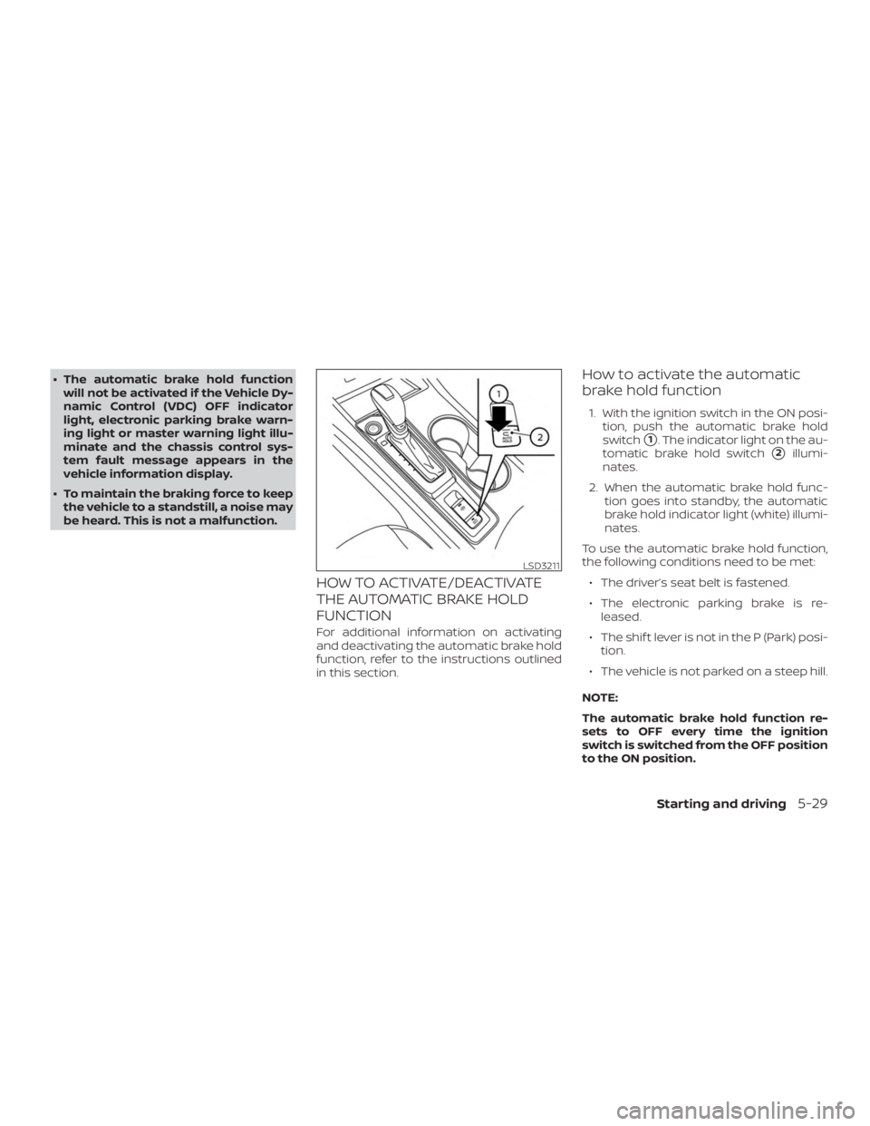
How to activate the automatic
brake hold function
1. With the ignition switch in the ON posi- tion, push the automatic brake hold
switch
�1. The indicator light on the au-
tomatic brake hold switch
�2illumi-
nates.
2. When the automatic brake hold func- tion goes into standby, the automatic
brake hold indicator light (white) illumi-
nates.
To use the automatic brake hold function,
the following conditions need to be met: ∙ The driver’s seat belt is fastened.
∙ The electronic parking brake is re- leased.
∙ The shif t lever is not in the P (Park) posi- tion.
∙ The vehicle is not parked on a steep hill.
NOTE:
The automatic brake hold function re-
sets to OFF every time the ignition
switch is switched from the OFF position
to the ON position.
Page 334 of 559

∙ Cruise control warning (yellow): Indi-cates that there is a malfunction in
the ICC system
2. Set vehicle speed indicator: This indicator indicates the set vehicle
speed. For Canadian models, the
speed is displayed in km/h.
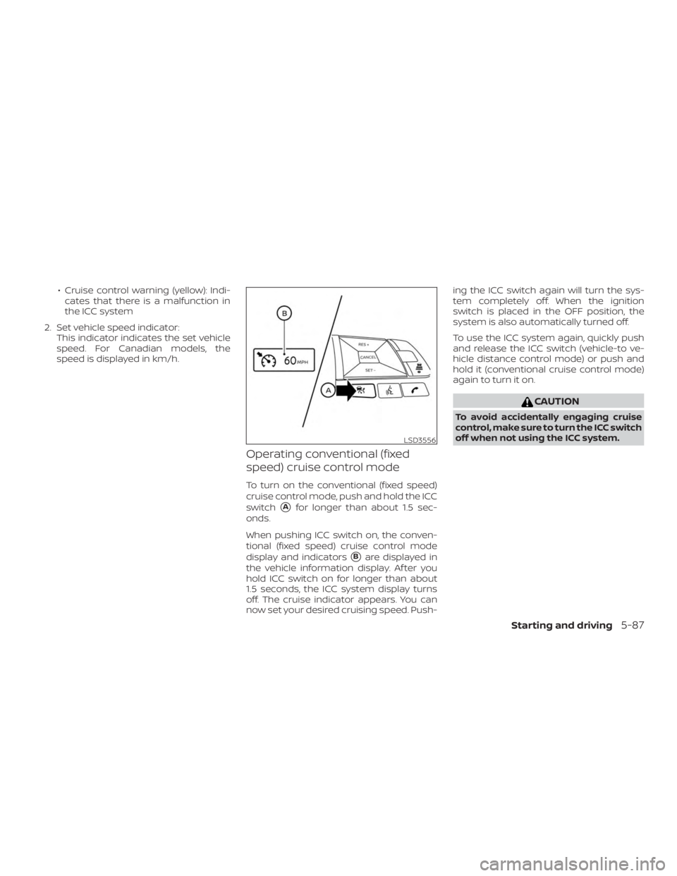
Operating conventional (fixed
speed) cruise control mode
To turn on the conventional (fixed speed)
cruise control mode, push and hold the ICC
switch
�Afor longer than about 1.5 sec-
onds.
When pushing ICC switch on, the conven-
tional (fixed speed) cruise control mode
display and indicators
�Bare displayed in
the vehicle information display. Af ter you
hold ICC switch on for longer than about
1.5 seconds, the ICC system display turns
off. The cruise indicator appears. You can
now set your desired cruising speed. Push- ing the ICC switch again will turn the sys-
tem completely off. When the ignition
switch is placed in the OFF position, the
system is also automatically turned off.
To use the ICC system again, quickly push
and release the ICC switch (vehicle-to ve-
hicle distance control mode) or push and
hold it (conventional cruise control mode)
again to turn it on.
Page 370 of 559
your desired cruising speed. Pushing the
ProPILOT Assist switch again will turn the
system completely off. When the ignition
switch is placed in the OFF position, the
system is also automatically turned off.
To use the ICC system again, quickly push
and release the ProPILOT Assist switch
(vehicle-to vehicle distance control mode)
or push and hold it (conventional cruise
control mode) again to turn it on.
Page 415 of 559
∙ HEADED DOWNHILL WITH CURB�A:
Turn the wheels into the curb and
move the vehicle forward until the curb
side wheel gently touches the curb.
∙ HEADED UPHILL WITH CURB
�B:
Turn the wheels away from the curb
and move the vehicle back until the
curb side wheel gently touches the
curb.
∙ HEADED UPHILL OR DOWNHILL, NO CURB
�C:
Turn the wheels toward the side of the
road so the vehicle will move away
from the center of the road if it moves.
4. Place the ignition switch in the LOCK position.
Page 441 of 559
WARNING
Always follow the instructions below.
Failure to do so could result in damage
to the charging system and cause per-
sonal injury.1. If the booster battery is in another ve- hicle, position the two vehicles to bring
their batteries near each other.
Do not allow the two vehicles to
touch. 2. Apply the parking brake. Move the shif t
lever to P (Park). Switch off all unneces-
sary electrical systems (lights, heater,
air conditioner, etc.).
3. Place the ignition switch in the LOCK position.
4. Connect the jumper cables in the se- quence illustrated (
�A,�B,�C,�D).