2022 KIA SPORTAGE stop start
[x] Cancel search: stop startPage 489 of 630
What to do in an emergency
30
6
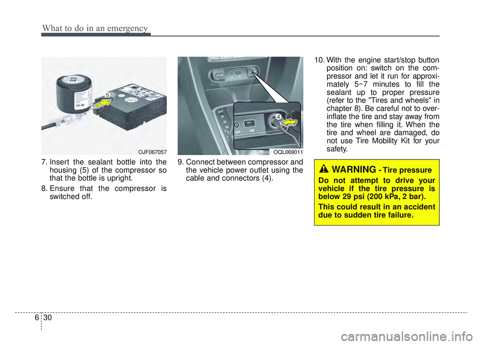
7. Insert the sealant bottle into the
housing (5) of the compressor so
that the bottle is upright.
8. Ensure that the compressor is switched off. 9. Connect between compressor and
the vehicle power outlet using the
cable and connectors (4). 10. With the engine start/stop button
position on: switch on the com-
pressor and let it run for approxi-
mately 5~7 minutes to fill the
sealant up to proper pressure
(refer to the "Tires and wheels" in
chapter 8). Be careful not to over-
inflate the tire and stay away from
the tire when filling it. When the
tire and wheel are damaged, do
not use Tire Mobility Kit for your
safety.
OJF067057OQL069011
WARNING- Tire pressure
Do not attempt to drive your
vehicle if the tire pressure is
below 29 psi (200 kPa, 2 bar).
This could result in an accident
due to sudden tire failure.
Page 490 of 630
631
What to do in an emergency
11. Switch off the compressor.
12. Detach the hose from the sealantbottle connector and from the tire
valve.
Return the Tire Mobility Kit to its stor-
age location in the vehicle.Distributing the sealant
13. Immediately drive approximately 4 ~ 6 miles (7 ~ 10 km or, about
10 min) to evenly distribute the
sealant in the tire.
Checking the tire inflation
pressure
1. After driving approximately 4 ~ 6miles (7 ~ 10 km or about 10 min-
utes), stop at a suitable location.
2. Connect the filling hose (3) of the compressor (clip mounted side)
directly and then connect the filling
hose (3) (opposite side) to the tire
valve.
3. Connect between compressor and the vehicle power outlet using the
cable and connectors.
4. Adjust the tire inflation pressure to 29 psi (200 kPa). With the Engine
Start/Stop button ON position,
proceed as follows.
- To increase the inflation pres- sure: Switch on the compressor,
position I. To check the current
inflation pressure setting, briefly
switch off the compressor.
CAUTION
Do not exceed a speed of 50 mph (80 km/h). If possible, donot fall below a speed of 12 mph(20 km/h).
While driving, if you experienceany unusual vibration, ride dis-turbance or noise, reduce yourspeed and drive with cautionuntil you can safely pull off ofthe side of the road. Call forroad side service or towing.
When you use the Tire MobilityKit, the wheel may be stained bysealant. Therefore, remove thetire pressure sensors and haveyour vehicle inspected by anauthorized Kia dealer.WARNING
Carbon monoxide poisoning
and suffocation is possible if the
engine is left running in a poorly
ventilated or unventilated loca-
tion (such as inside a building).
Page 496 of 630
637
What to do in an emergency
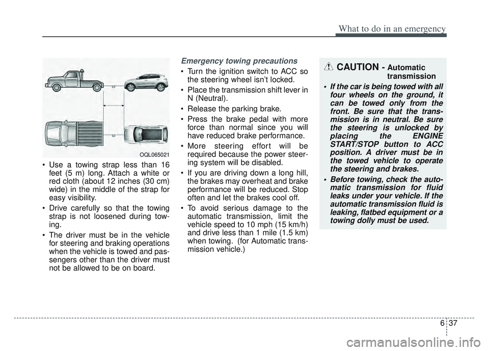
• Use a towing strap less than 16feet (5 m) long. Attach a white or
red cloth (about 12 inches (30 cm)
wide) in the middle of the strap for
easy visibility.
Drive carefully so that the towing strap is not loosened during tow-
ing.
The driver must be in the vehicle for steering and braking operations
when the vehicle is towed and pas-
sengers other than the driver must
not be allowed to be on board.
Emergency towing precautions
Turn the ignition switch to ACC sothe steering wheel isn’t locked.
Place the transmission shift lever in N (Neutral).
Release the parking brake.
Press the brake pedal with more force than normal since you will
have reduced brake performance.
More steering effort will be required because the power steer-
ing system will be disabled.
If you are driving down a long hill, the brakes may overheat and brake
performance will be reduced. Stop
often and let the brakes cool off.
To avoid serious damage to the automatic transmission, limit the
vehicle speed to 10 mph (15 km/h)
and drive less than 1 mile (1.5 km)
when towing. (for Automatic trans-
mission vehicle.)CAUTION - Automatic
transmission
• If the car is being towed with all four wheels on the ground, itcan be towed only from thefront. Be sure that the trans-mission is in neutral. Be surethe steering is unlocked byplacing the ENGINESTART/STOP button to ACCposition. A driver must be inthe towed vehicle to operatethe steering and brakes.
Before towing, check the auto- matic transmission for fluidleaks under your vehicle. If theautomatic transmission fluid isleaking, flatbed equipment or atowing dolly must be used.
OQL065021
Page 520 of 630
Maintenance
24
7
(Continued)
1. Wash the undercarriage of your
vehicle regularly throughout the
winter and do a thorough washing
in the spring to remove road salt
and other de-icing chemicals.
2. Monitor the brake system for signs of corrosion by having regu-
lar professional inspections and
watching for signs of problems,
including loss of brake fluid,
unusual leaks and soft or spongy
feel in the brake pedal.
3. Replace the entire brake pipe assembly if you find severe corro-
sion that causes scaling or flaking
of brake components.Brake fluid
Check the brake fluid level in the
brake fluid reservoir. The level should
be between “MIN” and “MAX” marks
on the side of the reservoir. Use only
hydraulic brake fluid conforming to
DOT 3 or DOT 4 specification.
Parking brake
Inspect the parking brake system
including the parking brake pedal
and cables.
Brake discs, pads and calipers
Check the pads for excessive wear,
discs for run out and wear, and
calipers for fluid leakage.
Exhaust pipe and muffler
Visually inspect the exhaust pipes,
muffler and hangers for cracks, dete-
rioration, or damage. Start the engine
and listen carefully for any exhaust
gas leakage. Tighten connections or
replace parts as necessary.
Suspension mounting bolts
Check the suspension connections
for looseness or damage. Retighten
to the specified torque.
Steering gear box, linkage &
boots/lower arm ball joint
With the vehicle stopped and engine
off, check for excessive free-play in
the steering wheel.
Check the linkage for bends or dam-
age. Check the dust boots and ball
joints for deterioration, cracks, or dam-
age. Replace any damaged parts.
Page 565 of 630
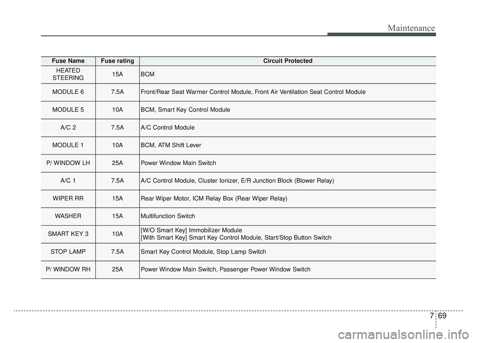
769
Maintenance
Fuse NameFuse ratingCircuit Protected
HEATED
STEERING15ABCM
MODULE 67.5AFront/Rear Seat Warmer Control Module, Front Air Ventilation Seat Control Module
MODULE 510ABCM, Smart Key Control Module
A/C 27.5AA/C Control Module
MODULE 110ABCM, ATM Shift Lever
P/ WINDOW LH25APower Window Main Switch
A/C 17.5AA/C Control Module, Cluster Ionizer, E/R Junction Block (Blower Relay)
WIPER RR15ARear Wiper Motor, ICM Relay Box (Rear Wiper Relay)
WASHER15AMultifunction Switch
SMART KEY 310A[W/O Smart Key] Immobilizer Module
[With Smart Key] Smart Key Control Module, Start/Stop Button Switch
STOP LAMP7.5ASmart Key Control Module, Stop Lamp Switch
P/ WINDOW RH25APower Window Main Switch, Passenger Power Window Switch
Page 569 of 630
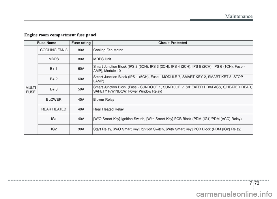
773
Maintenance
Fuse NameFuse ratingCircuit Protected
MULTIFUSE
COOLING FAN 380ACooling Fan Motor
MDPS80AMDPS Unit
B+ 160ASmart Junction Block (IPS 2 (5CH), IPS 3 (2CH), IPS 4 (2CH), IPS 5 (2CH), IPS 6 (\
1CH), Fuse -
AMP), Module 10
B+ 260ASmart Junction Block (IPS 1 (5CH), Fuse - MODULE 7, SMART KEY 2, SMART KET 3, STOP
LAMP)
B+ 350ASmart Junction Block (Fuse - SUNROOF 1, SUNROOF 2, S/HEATER DRV/PASS, S/HEATER REAR,
SAFETY P/WINDOW, Power Window Relay)
BLOWER40ABlower Relay
REAR HEATED40ARear Heated Relay
IG140A[W/O Smart Key] Ignition Switch, [With Smart Key] PCB Block (PDM (IG1)/PDM (ACC) Relay)
IG230AStart Relay, [W/O Smart Key] Ignition Switch, [With Smart Key] PCB Block (PDM (IG2) Relay)
Engine room compartment fuse panel
Page 600 of 630
Maintenance
104
7
Do not operate the engine in con-
fined or closed areas (such as
garages) any more than what is
necessary to move the vehicle in or
out of the area.
When the vehicle is stopped in an open area for more than a short
time with the engine running,
adjust the ventilation system (as
needed) to draw outside air into the
vehicle.
Never sit in a parked or stopped vehicle for any extended time with
the engine running.
When the engine stalls or fails to start, excessive attempts to restart
the engine may cause damage to
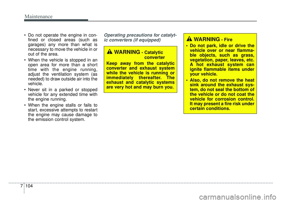
the emission control system.Operating precautions for catalyt-
ic converters (if equipped)
WARNING- Catalytic converter
Keep away from the catalytic
converter and exhaust system
while the vehicle is running or
immediately thereafter. The
exhaust and catalytic systems
are very hot and may burn you.
WARNING- Fire
Do not park, idle or drive the vehicle over or near flamma-
ble objects, such as grass,
vegetation, paper, leaves, etc.
A hot exhaust system can
ignite flammable items under
your vehicle.
Also, do not remove the heat sink around the exhaust sys-
tem, do not seal the bottom of
the vehicle or do not coat the
vehicle for corrosion control.
It may present a fire risk under
certain conditions.
Page 622 of 630
Index
4I
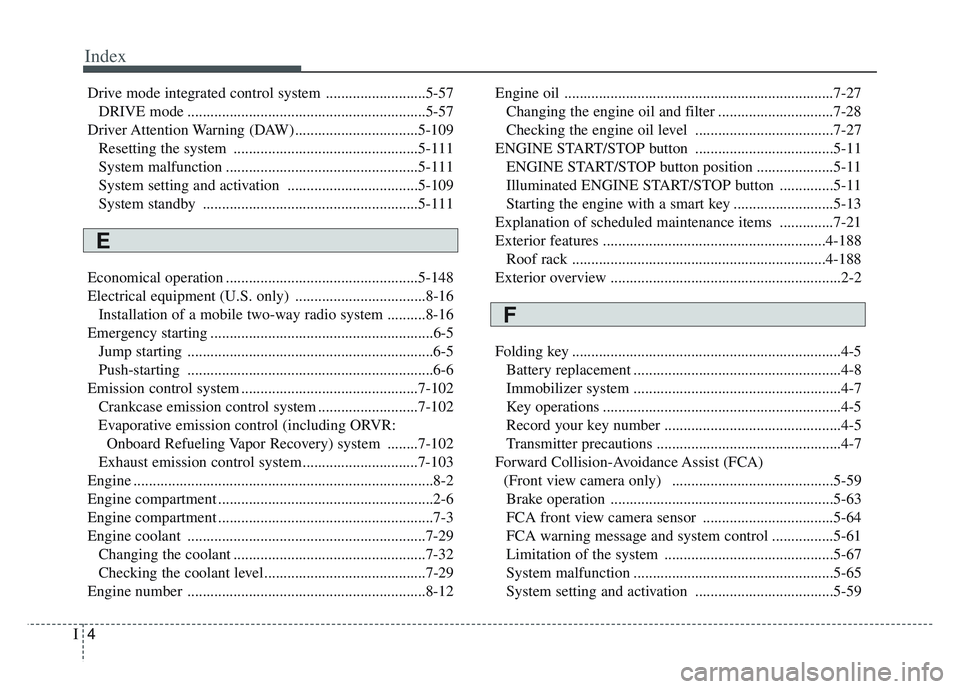
Drive mode integrated control system ..........................5-57DRIVE mode ..............................................................5-57
Driver Attention Warning (DAW)................................5-109 Resetting the system ................................................5-111
System malfunction ..................................................5-111
System setting and activation ..................................5-109
System standby ........................................................5-111
Economical operation ..................................................5-148
Electrical equipment (U.S. only) ..................................8-16 Installation of a mobile two-way radio system ..........8-16
Emergency starting ..........................................................6-5 Jump starting ................................................................6-5
Push-starting ................................................................6-6
Emission control system ..............................................7-102 Crankcase emission control system ..........................7-102
Evaporative emission control (including ORVR: Onboard Refueling Vapor Recovery) system ........7-102
Exhaust emission control system ..............................7-103
Engine ........................................................................\
......8-2
Engine compartment ........................................................2-6
Engine compartment ........................................................7-3
Engine coolant ..............................................................7-29 Changing the coolant ..................................................7-32
Checking the coolant level..........................................7-29
Engine number ..............................................................8-12 Engine oil ......................................................................7-\
27
Changing the engine oil and filter ..............................7-28
Checking the engine oil level ....................................7-27
ENGINE START/STOP button ....................................5-11 ENGINE START/STOP button position ....................5-11
Illuminated ENGINE START/STOP button ..............5-11
Starting the engine with a smart key ..........................5-13
Explanation of scheduled maintenance items ..............7-21
Exterior features ..........................................................4-188 Roof rack ..................................................................4-188
Exterior overview ............................................................2-2
Folding key ......................................................................4-\
5 Battery replacement ......................................................4-8
Immobilizer system ......................................................4-7
Key operations ..............................................................4-5
Record your key number ..............................................4-5
Transmitter precautions ................................................4-7
Forward Collision-Avoidance Assist (FCA) (Front view camera only) ..........................................5-59Brake operation ..........................................................5-63
FCA front view camera sensor ..................................5-64
FCA warning message and system control ................5-61
Limitation of the system ............................................5-67
System malfunction ....................................................5-65
System setting and activation ....................................5-59
E
F