Page 517 of 579

09
9-31
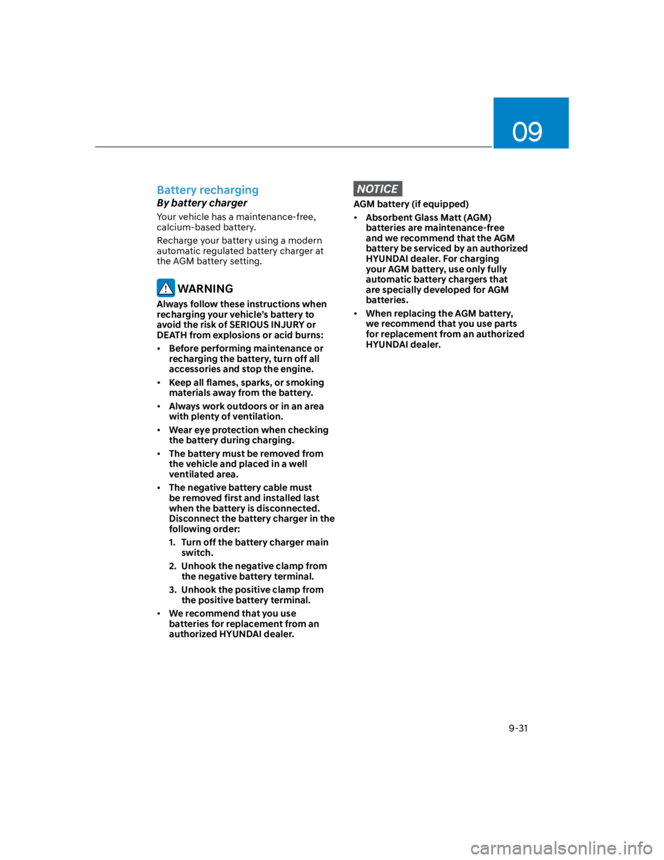
Battery recharging
By battery charger
Your vehicle has a maintenance-free,
calcium-based battery.
Recharge your battery using a modern
automatic regulated battery charger at
the AGM battery setting.
WARNING
Always follow these instructions when
recharging your vehicle’s battery to
avoid the risk of SERIOUS INJURY or
DEATH from explosions or acid burns:
Before performing maintenance or
recharging the battery, turn off all
accessories and stop the engine.
Keep all flames, sparks, or smoking
materials away from the battery.
Always work outdoors or in an area
with plenty of ventilation.
Wear eye protection when checking
the battery during charging.
The battery must be removed from
the vehicle and placed in a well
ventilated area.
The negative battery cable must
be removed first and installed last
when the battery is disconnected.
Disconnect the battery charger in the
following order:
1. Turn off the battery charger main
switch.
2. Unhook the negative clamp from
the negative battery terminal.
3. Unhook the positive clamp from
the positive battery terminal.
We recommend that you use
batteries for replacement from an
authorized HYUNDAI dealer.
NOTICE
AGM battery (if equipped)
Absorbent Glass Matt (AGM)
batteries are maintenance-free
and we recommend that the AGM
battery be serviced by an authorized
HYUNDAI dealer. For charging
your AGM battery, use only fully
automatic battery chargers that
are specially developed for AGM
batteries.
When replacing the AGM battery,
we recommend that you use parts
for replacement from an authorized
HYUNDAI dealer.
Page 518 of 579
Maintenance
9-32
By jump starting
After a jump start from a good battery,
drive the vehicle for 20-30 minutes
before it is shutoff. The vehicle may
not restart if you shut it off before the
battery had a chance to adequately
recharge. See “Jump Starting” in chapter
8 for more information on jump starting
procedures.
Information
Reset items
The following items may need to be reset
after the battery has been discharged or
the battery has been disconnected.
Auto up/down window (see chapter 5)
Sunroof (see chapter 5)
Trip computer (see chapter 5)
Climate control system (see chapter 5)
Clock (see chapter 5)
Infotainment system (see
infotainment system manual)
Page 536 of 579

Maintenance
9-50
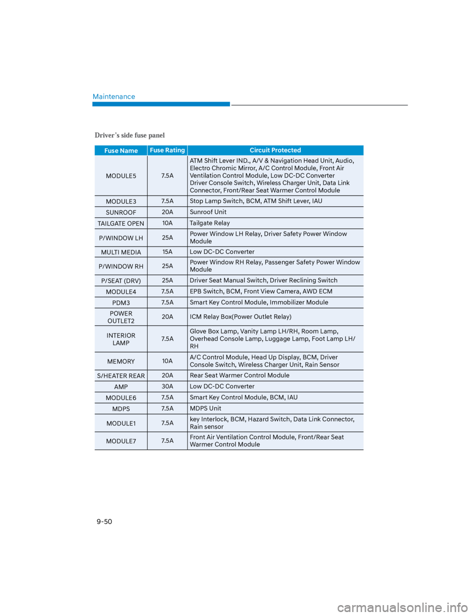
Fuse NameFuse Rating Circuit Protected
MODULE57.5A
ATM Shift Lever IND., A/V & Navigation Head Unit, Audio,
Electro Chromic Mirror, A/C Control Module, Front Air
Ventilation Control Module, Low DC-DC Converter
Driver Console Switch, Wireless Charger Unit, Data Link
Connector, Front/Rear Seat Warmer Control Module
MODULE37.5A Stop Lamp Switch, BCM, ATM Shift Lever, IAU
SUNROOF20A Sunroof Unit
TAILGATE OPEN10A Tailgate Relay
P/WINDOW LH25APower Window LH Relay, Driver Safety Power Window
Module
MULTI MEDIA15A Low DC-DC Converter
P/WINDOW RH25APower Window RH Relay, Passenger Safety Power Window
Module
P/SEAT (DRV)25A Driver Seat Manual Switch, Driver Reclining Switch
MODULE47.5A EPB Switch, BCM, Front View Camera, AWD ECM
PDM37.5A Smart Key Control Module, Immobilizer Module
POWER
OUTLET220A ICM Relay Box(Power Outlet Relay)
INTERIOR
LAMP7.5A
Glove Box Lamp, Vanity Lamp LH/RH, Room Lamp,
Overhead Console Lamp, Luggage Lamp, Foot Lamp LH/
RH
MEMORY10AA/C Control Module, Head Up Display, BCM, Driver
Console Switch, Wireless Charger Unit, Rain Sensor
S/HEATER REAR20A Rear Seat Warmer Control Module
AMP30A Low DC-DC Converter
MODULE67.5A Smart Key Control Module, BCM, IAU
MDPS7.5A MDPS Unit
MODULE17.5Akey Interlock, BCM, Hazard Switch, Data Link Connector,
Rain sensor
MODULE77.5AFront Air Ventilation Control Module, Front/Rear Seat
Warmer Control Module
Page 537 of 579

09
9-51
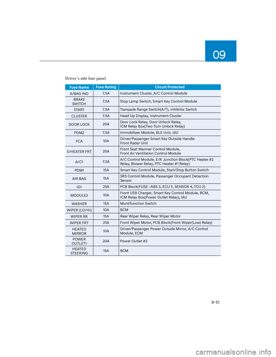
Fuse NameFuse Rating Circuit Protected
A/BAG IND7.5A Instrument Cluster, A/C Control Module
BRAKE
SWITCH7.5A Stop Lamp Switch, Smart Key Control Module
START7.5A Transaxle Range Switch(A/T), Inhibitor Switch
CLUSTER7.5A Head Up Display, Instrument Cluster
DOOR LOCK20ADoor Lock Relay, Door Unlock Relay,
ICM Relay Box(Two Turn Unlock Relay)
PDM27.5A Immobilizer Module, BLE Unit, IAU
FCA10ADriver/Passenger Smart Key Outside Handle
Front Radar Unit
S/HEATER FRT20AFront Seat Warmer Control Module,
Front Air Ventilation Control Module
A/C17.5AA/C Control Module, E/R Junction Block(PTC Heater #2
Relay, Blower Relay, PTC Heater #1 Relay)
PDM115A Smart Key Control Module, Start/Stop Button Switch
AIR BAG15ASRS Control Module, Passenger Occupant Detection
Sensor
IG125A PCB Block(FUSE : ABS 3, ECU 5, SENSOR 4, TCU 2)
MODULE210AFront USB Charger, Smart Key Control Module, BCM,
ICM Relay Box(Power Outlet Relay), IAU
WASHER15A Muntifunction Switch
WIPER (LO/HI)10A BCM
WIPER RR15A Rear Wiper Relay, Rear Wiper Motor
WIPER FRT25A Front Wiper Motor, PCB Block(Front Wiper(Low) Relay)
HEATED
MIRROR10ADriver/Passenger Power Outside Mirror, A/C Control
Module, ECM
POWER
OUTLET120A Power Outlet #2
HEATED
STEERING15A BCM
Page 574 of 579

Index
I-8
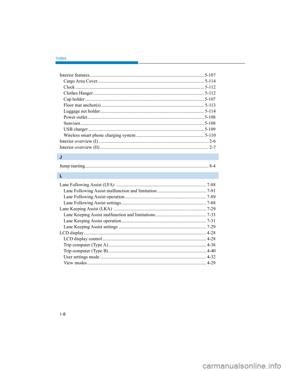
Interior features.................................................................................................. 5-107
Cargo Area Cover ........................................................................................... 5-114
Clock .............................................................................................................. 5-112
Clothes Hanger ............................................................................................... 5-112
Cup holder ...................................................................................................... 5-107
Floor mat anchor(s) ........................................................................................ 5-113
Luggage net holder......................................................................................... 5-114
Power outlet.................................................................................................... 5-108
Sunvisor.......................................................................................................... 5-108
USB charger ................................................................................................... 5-109
Wireless smart phone charging system .......................................................... 5-110
Interior overview (I) .............................................................................................. 2-6
Interior overview (II) ............................................................................................. 2-7
J
Jump starting.......................................................................................................... 8-4
L
Lane Following Assist (LFA) ............................................................................. 7-88
Lane Following Assist malfunction and limitation .......................................... 7-91
Lane Following Assist operation...................................................................... 7-89
Lane Following Assist settings......................................................................... 7-88
Lane Keeping Assist (LKA) ............................................................................... 7-29
Lane Keeping Assist malfunction and limitations............................................ 7-33
Lane Keeping Assist operation......................................................................... 7-31
Lane Keeping Assist settings ........................................................................... 7-29
LCD display......................................................................................................... 4-28
LCD display control ......................................................................................... 4-28
Trip computer (Type A).................................................................................... 4-38
Trip computer (Type B).................................................................................... 4-40
User settings mode ........................................................................................... 4-32
View modes ...................................................................................................... 4-29