2022 HYUNDAI KONA EV trip computer
[x] Cancel search: trip computerPage 144 of 548
4
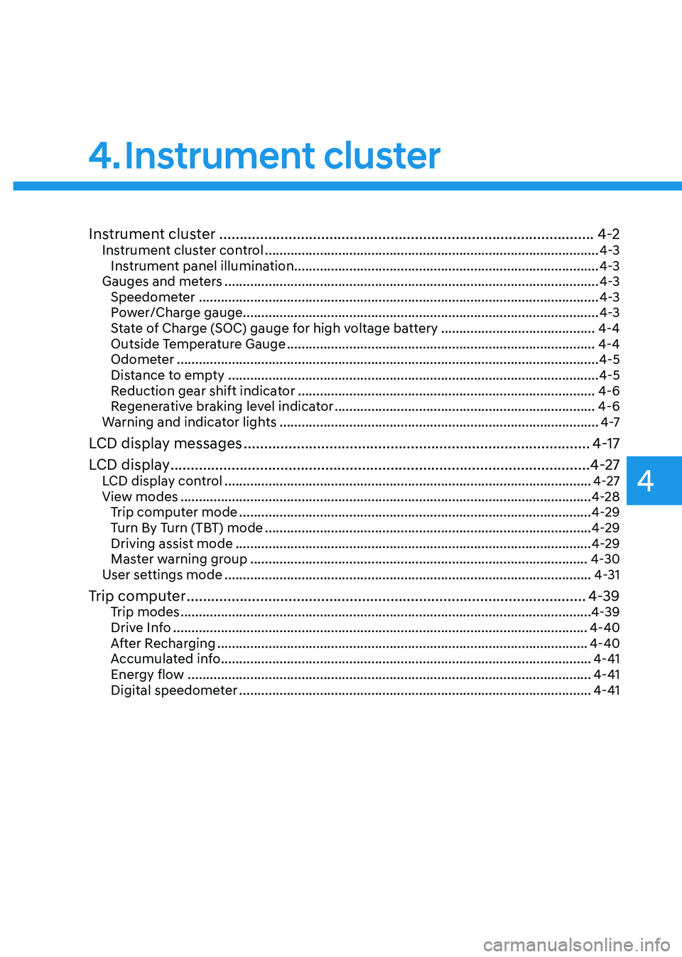
Instrument cluster ............................................................................................ 4-2
Instrument cluster control ........................................................................................... 4-3
Instrument panel illumination ................................................................................... 4-3
Gauges and meters ...................................................................................................... 4-3
Speedometer ............................................................................................................. 4-3
Power/Charge gauge................................................................................................. 4-3
State of Charge (SOC) gauge for high voltage battery ..........................................4-4
Outside Temperature Gauge .................................................................................... 4-4
Odometer ................................................................................................................... 4-5
Distance to empty ..................................................................................................... 4-5
Reduction gear shift indicator ................................................................................. 4-6
Regenerative braking level indicator ....................................................................... 4-6
Warning and indicator lights ....................................................................................... 4 -7
LCD display messages ..................................................................................... 4-17
LCD display ....................................................................................................... 4-27
LCD display control .................................................................................................... 4-27
View modes ................................................................................................................ 4-28
Trip computer mode ................................................................................................ 4-29
Turn By Turn (TBT) mode ......................................................................................... 4-29
Driving assist mode ................................................................................................. 4-29
Master warning group ............................................................................................ 4-30
User settings mode .................................................................................................... 4-31
Trip computer .................................................................................................. 4-39
Trip modes ................................................................................................................ 4-39
Drive Info ................................................................................................................. 4-40
After Recharging ..................................................................................................... 4-40
Accumulated info ..................................................................................................... 4-41
Energy flow .............................................................................................................. 4-41
Digital speedometer ................................................................................................ 4-41
4. Instrument cluster
Page 145 of 548
4-2
Instrument cluster
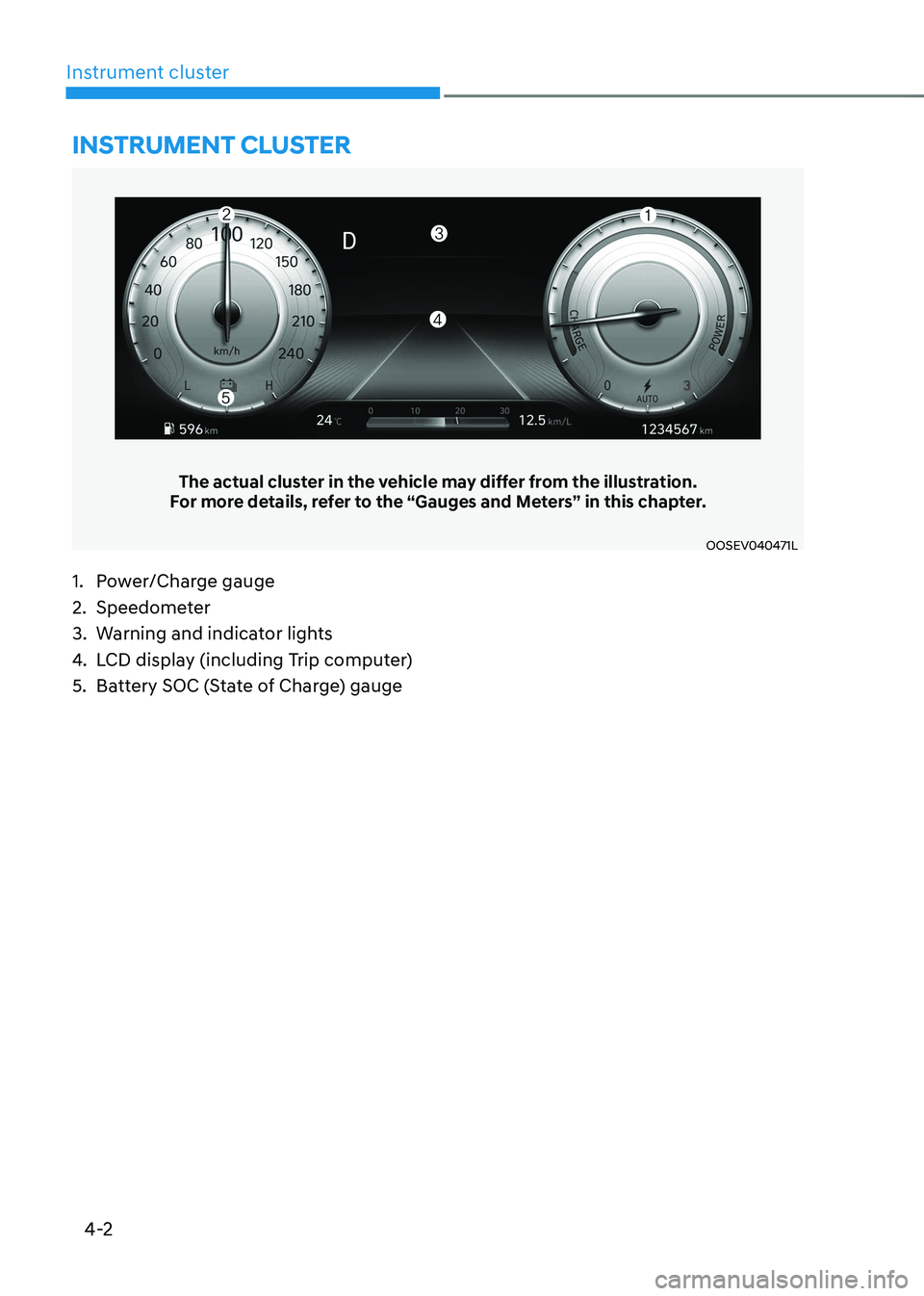
The actual cluster in the vehicle may differ from the illustration.
For more details, refer to the “Gauges and Meters” in this chapter.
OOSEV040471L
Instrument cluster
1. Power/Charge gauge
2. Speedometer
3. Warning and indicator lights
4. LCD display (including Trip computer)
5. Battery SOC (State of Charge) gauge
Page 171 of 548
Instrument cluster
4-28
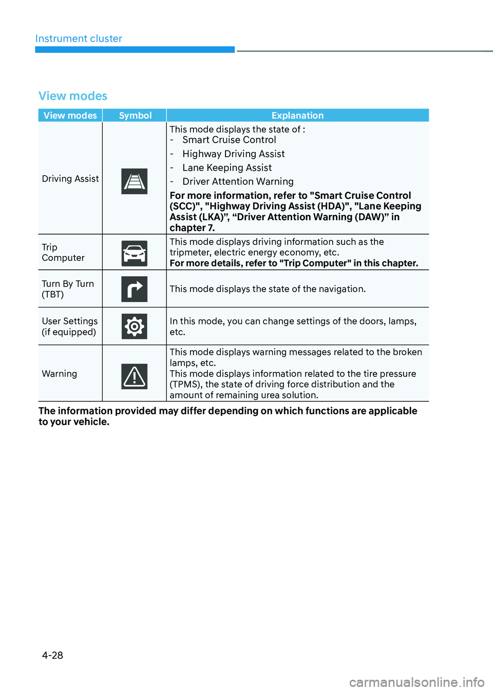
View modes
View modes Symbol Explanation
Driving Assist
This mode displays the state of : - Smart Cruise Control
- Highway Driving Assist
- Lane Keeping Assist
- Driver Attention Warning
For more information, refer to "Smart Cruise Control
(SCC)", "Highway Driving Assist (HDA)", "Lane Keeping
Assist (LKA)”, “Driver Attention Warning (DAW)” in
chapter 7.
Trip
Computer
This mode displays driving information such as the
tripmeter, electric energy economy, etc.
For more details, refer to "Trip Computer" in this chapter.
Turn By Turn
(TBT)
This mode displays the state of the navigation.
User Settings (if equipped)
In this mode, you can change settings of the doors, lamps,
etc.
Warning
This mode displays warning messages related to the broken
lamps, etc.
This mode displays information related to the tire pressure
(TPMS), the state of driving force distribution and the
amount of remaining urea solution.
The information provided may differ depending on which functions are applicable
to your vehicle.
Page 172 of 548
04
4-29
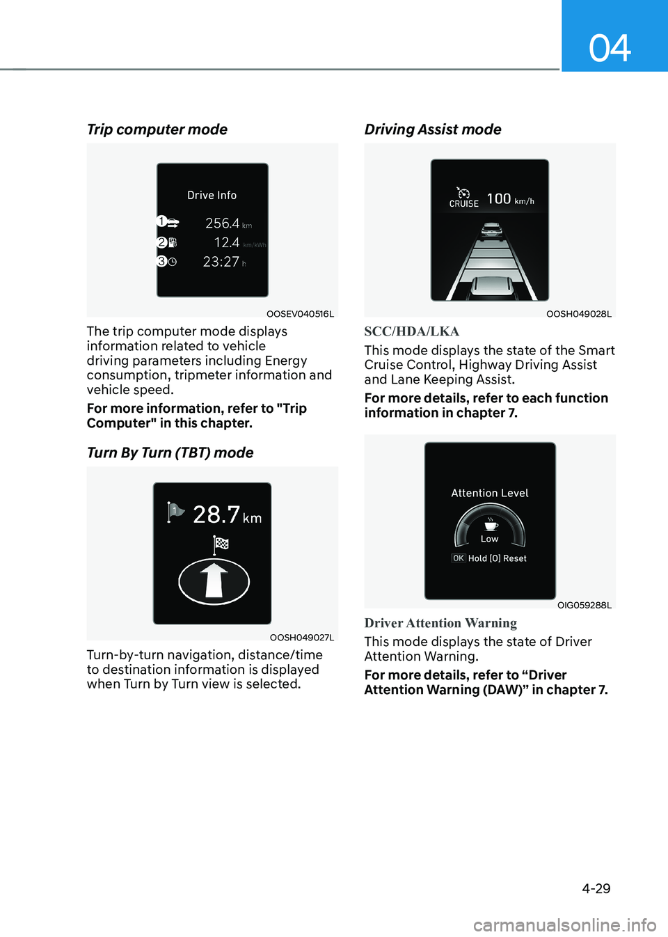
Trip computer mode
OOSEV040516L
The trip computer mode displays
information related to vehicle
driving parameters including Energy
consumption, tripmeter information and
vehicle speed.
For more information, refer to "Trip
Computer" in this chapter.
Turn By Turn (TBT) mode
OOSH049027L
Turn-by-turn navigation, distance/time
to destination information is displayed
when Turn by Turn view is selected. Driving Assist mode
OOSH049028L
SCC/HDA/LKA
This mode displays the state of the Smart
Cruise Control, Highway Driving Assist
and Lane Keeping Assist.
For more details, refer to each function
information in chapter 7.
OIG059288L
Driver Attention Warning
This mode displays the state of Driver
Attention Warning.
For more details, refer to “Driver
Attention Warning (DAW)” in chapter 7.
Page 182 of 548
04
4-39
trIp computer
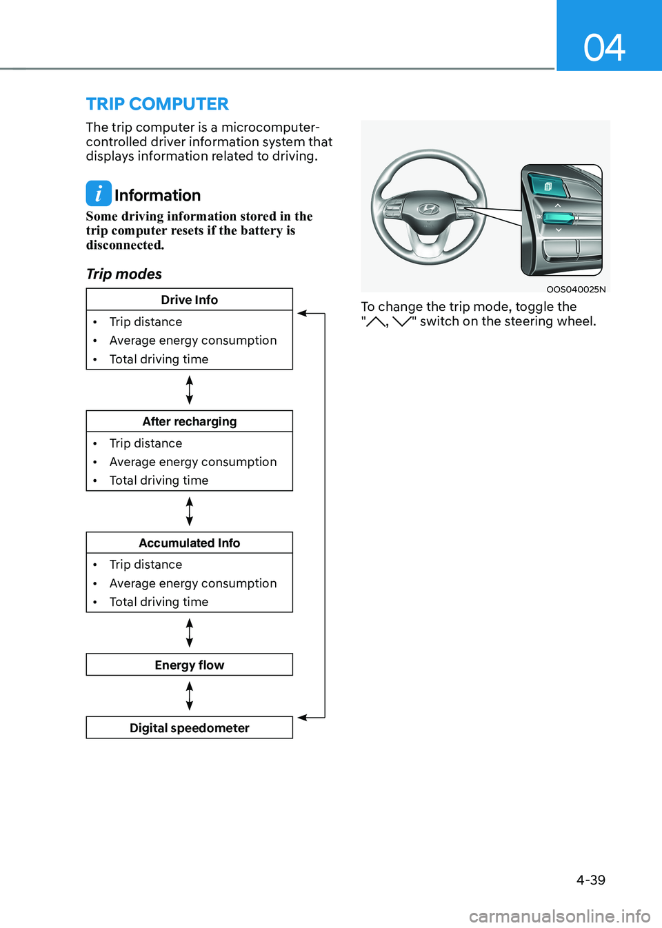
The trip computer is a microcomputer-
controlled driver information system that
displays information related to driving.
Information
Some driving information stored in the
trip computer resets if the battery is disconnected.
Trip modes
Drive Info
• Trip distance
• Average energy consumption
• Total driving time
After recharging
• Trip distance
• Average energy consumption
• Total driving time
Accumulated Info
• Trip distance
• Average energy consumption
• Total driving time
Energy flow
Digital speedometer
OOS040025N
To change the trip mode, toggle the "
, " switch on the steering wheel.
Page 495 of 548
09
9-19
• Wear eye protection when checking
the battery during charging.
• The battery must be removed from
the vehicle and placed in a well
ventilated area.
• Watch the battery during charging,
and stop or reduce the charging
rate if the battery cells begin boiling
violently.
• The negative battery cable must
be removed first and installed last
when the battery is disconnected.
Disconnect the battery charger in the
following order:
(1) Turn off the battery charger main
switch.
(2) Unhook the negative clamp from the negative battery terminal.
(3) Unhook the positive clamp from the positive battery terminal.
• Always use a genuine HYUNDAI
approved battery or the equivalent
specified for your vehicle when you
replace the battery. By jump starting
After a jump start from a good battery,
drive the vehicle for 20-30 minutes
before it is shutoff. The vehicle may
not restart if you shut it off before the
battery had a chance to adequately
recharge. See “Jump Starting” in chapter
8 for more information on jump starting
procedures.
Information
An inappropriately disposed of battery can be harmful to the
environment and human health.
Dispose of the battery according to your
local law(s) or regulations.
Reset items
The following items may need to be reset
after the battery has been discharged or
the battery has been disconnected. • Auto up/down window
• Sunroof
• Trip computer
• Climate control system
• Clock
• Audio system
Page 547 of 548
Index
I-12
Tire Pressure Monitoring System (TPMS) ............................................................8-6
Changing a tire with TPMS ................................................................................ 8-9
Check tire pressure ............................................................................................. 8-6
Low tire pressure position telltale and tire pressure telltale ...............................8-8
Low tire pressure telltale .................................................................................... 8-8
Tire pressure monitoring system ........................................................................ 8-7
TPMS (Tire Pressure Monitoring System) malfunction indicator .....................8-9
Tire specification and pressure label ................................................................... 2-13
Tires and wheels .................................................................................................... 2-9
Towing ................................................................................................................. 8-18
Emergency towing ............................................................................................ 8-20
Removable towing hook .................................................................................. 8-19
Towing service ................................................................................................. 8-18
Trailer towing ...................................................................................................... 6-53
Trip computer ...................................................................................................... 4-39
V
Vehicle certification label .................................................................................... 2-12
Vehicle identification number (VIN) ................................................................... 2-12
Vehicle load limit ................................................................................................. 6-48
Overloading ...................................................................................................... 6-48
The loading information label .......................................................................... 6-49
Volume and weight .............................................................................................. 2-10