2022 HYUNDAI KONA EV lights
[x] Cancel search: lightsPage 7 of 548
1
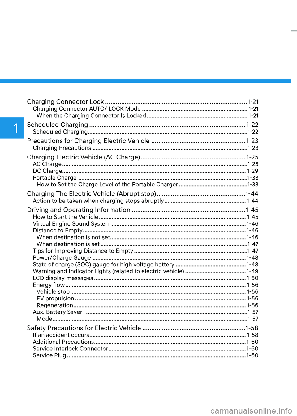
Charging Connector Lock ................................................................................ 1-21
Charging Connector AUTO/ LOCK Mode .................................................................. 1-21
When the Charging Connector Is Locked ...............................................................1-21
Scheduled Charging ........................................................................................ 1-22
Scheduled Charging....................................................................................................1-22
Precautions for Charging Electric Vehicle .....................................................1-23
Charging Precautions ................................................................................................. 1-23
Charging Electric Vehicle (AC Charge) ...........................................................1-25
AC Charge .................................................................................................................... 1-25
DC Charge................................................................................................................... 1-29 Portable Charge .......................................................................................................... 1-33
How to Set the Charge Level of the Portable Charger ...........................................1-33
Charging The Electric Vehicle (Abrupt stop) ..................................................1-44
Action to be taken when charging stops abruptly ...................................................1-44
Driving and Operating Information ................................................................ 1-45
How to Start the Vehicle ............................................................................................ 1-45
Virtual Engine Sound System .................................................................................... 1-46
Distance to Empty ...................................................................................................... 1-46
When destination is not set ..................................................................................... 1-46
When destination is set ............................................................................................ 1-47
Tips for Improving Distance to Empty ....................................................................... 1-47
Power/Charge Gauge ................................................................................................ 1-48
State of charge (SOC) gauge for high voltage battery ............................................1-48
Warning and Indicator Lights (related to electric vehicle) ......................................1-49
LCD display messages ............................................................................................... 1-50
Energy flow ................................................................................................................. 1-56
Vehicle stop .............................................................................................................. 1-56
EV propulsion ........................................................................................................... 1-56
Regeneration ............................................................................................................ 1-56
Aux. Battery Saver+ ..................................................................................................... 1-57
Mode .......................................................................................................................... 1-57
Safety Precautions for Electric Vehicle ..........................................................1-58
If an accident occurs .................................................................................................. 1-58
Additional Precautions ............................................................................................... 1-60
Service Interlock Connector ...................................................................................... 1-60
Service Plug ................................................................................................................ 1-60
Page 12 of 548
01
1 -7
main ComponenTs oF eleCTriC VeHiCle
Main Components of Electric
Vehicle
• On-Board Charger (OBC) : A device
that charges the high voltage battery
by converting AC power from a
charging station to DC power. Inverter
: A device that transforms direct
current (DC) from the high voltage
battery into alternating current (AC)
to supply power to the electric motor
and transforms AC back into DC when
available to charge the high voltage
battery.
• LDC : An LDC is a Low Voltage DC-to-
DC converter that transforms power
from the high voltage battery to the
low voltage battery (12V) in order
to supply electrical power to the
vehicle to operate the lights, wipers,
multimedia, etc.
• Electric Motor : A device that
converts electrical energy from the
high voltage battery into mechanical
energy which is then transferred as
rotational torque to the wheels in
order to drive the vehicle.
• Reduction gear : Delivers rotational
force of the motor to the tires at
appropriate speeds and torque.
• EV Battery (Lithium-ion) : On board
high voltage storage device with a
capacity up to 64 kWh
à OBC : On-Board Charger
à LDC : Low Voltage DC-DC Converter
WARNING
• Do not intentionally remove
or disassemble high voltage
components and high voltage
battery connectors and wires. Also,
be careful not to damage high
voltage components and the high
voltage battery. It may cause serious
injury and significantly impact the
performance and durability of the
vehicle.
• When inspection and maintenance
is required for high voltage
components and the high voltage
battery, we recommend that you
contact an authorized HYUNDAI
dealer.
High Voltage Battery
(lithium-ion polymer)
• The charge amount of the high
voltage battery may gradually
decrease when the vehicle is not
being driven.
• The battery capacity of the high
voltage battery may decrease when
the vehicle is stored in high/low
temperatures.
• Electric range may vary depending
on the driving conditions, even if the
charge amount is the same. The high
voltage battery may expend more
energy when driving at high speed or
uphill. These actions may reduce the
vehicle electric range.
• The high voltage battery is used when
using the air-conditioner / heater. This
may reduce the vehicle range. Make
sure to set moderate temperatures
when using the air-conditioner/heater.
• Natural degradation may occur with
the high voltage battery depending
on the number of years the vehicle
is used. This may reduce the vehicle
range.
Page 19 of 548
Foreword / Electric Vehicle System Overview
1-14
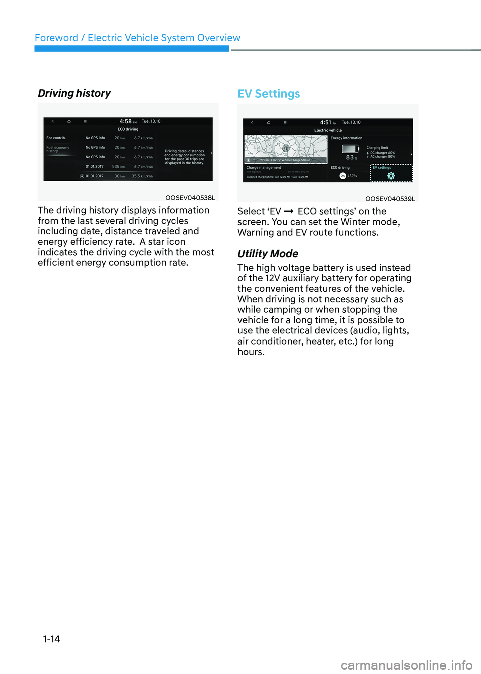
Driving history
OOSEV040538L
The driving history displays information
from the last several driving cycles
including date, distance traveled and
energy efficiency rate. A star icon
indicates the driving cycle with the most
efficient energy consumption rate.
EV Settings
OOSEV040539L
Select ‘EV ÞECO settings’ on the
screen. You can set the Winter mode,
Warning and EV route functions.
Utility Mode
The high voltage battery is used instead
of the 12V auxiliary battery for operating
the convenient features of the vehicle.
When driving is not necessary such as
while camping or when stopping the
vehicle for a long time, it is possible to
use the electrical devices (audio, lights,
air conditioner, heater, etc.) for long
hours.
Page 54 of 548

01
1-49
Warning and Indicator Lights
(related to electric vehicle)
Ready indicator
This indicator illuminates:
When the vehicle is ready to be driven. - ON : Normal driving is possible.
- OFF : Normal driving is not possible, or a problem has occurred.
- Blinking : Emergency driving.
When the ready indicator goes OFF
or blinks, there is a problem with the
system. In this case, have your vehicle
inspected by an authorized HYUNDAI
dealer.
Service Warning Light
This warning light illuminates:
• When the Start/Stop button is in the ON position.
- It illuminates for approximately 3 seconds and then goes off.
• When there is a problem with related
parts of the electric vehicle control
system, such as sensors, etc.
When the warning light illuminates while
driving, or does not go OFF after starting
the vehicle, have your vehicle inspected
by an authorized HYUNDAI dealer.
Power Down Warning Light
This warning light illuminates :
When the power output from the vehicle
is limited. The vehicle is in fail-safe mode.
Power from the vehicle is limited due to
one of the following reasons: - The state of charge (SOC) of the high voltage battery is very low. Typically
the Power Down Warning Light will
turn ON when the SOC is below 3%.
- The temperature of the EV drive motor or the high voltage battery is either
too high (overheating) or too low
(freezing)
- There is a problem with either the cooling system or a vehicle system
warning has occurred that may
interrupt normal driving
NOTICE
• Do not accelerate or start the vehicle
suddenly when the power down
warning light is ON.
• When the high voltage battery level
is low, the power down warning
illuminates and the power output
from the vehicle is limited. Charge
the battery immediately since your
vehicle may not drive uphill or skid
on a slope with the warning light ON.
Page 144 of 548
4
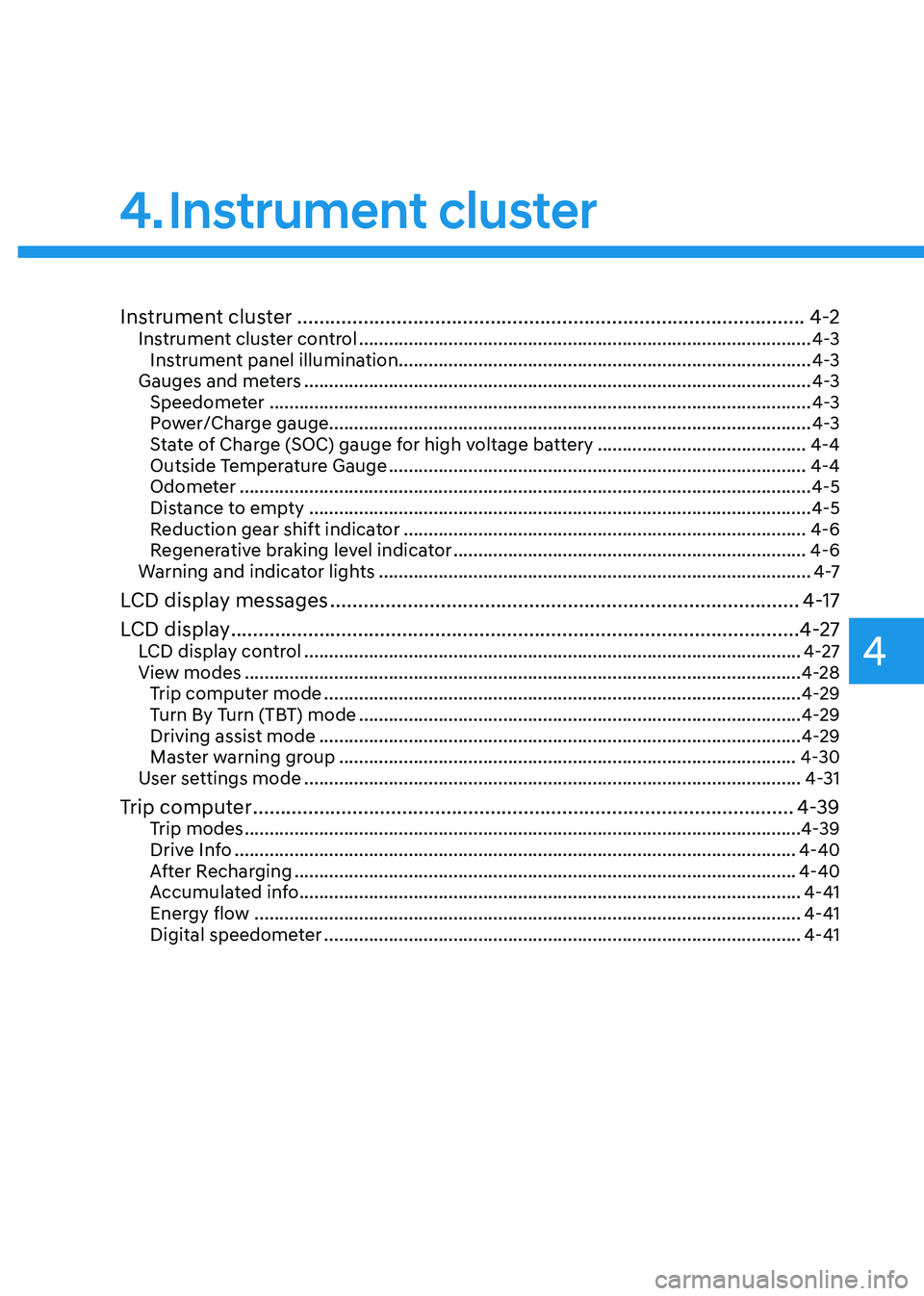
Instrument cluster ............................................................................................ 4-2
Instrument cluster control ........................................................................................... 4-3
Instrument panel illumination ................................................................................... 4-3
Gauges and meters ...................................................................................................... 4-3
Speedometer ............................................................................................................. 4-3
Power/Charge gauge................................................................................................. 4-3
State of Charge (SOC) gauge for high voltage battery ..........................................4-4
Outside Temperature Gauge .................................................................................... 4-4
Odometer ................................................................................................................... 4-5
Distance to empty ..................................................................................................... 4-5
Reduction gear shift indicator ................................................................................. 4-6
Regenerative braking level indicator ....................................................................... 4-6
Warning and indicator lights ....................................................................................... 4 -7
LCD display messages ..................................................................................... 4-17
LCD display ....................................................................................................... 4-27
LCD display control .................................................................................................... 4-27
View modes ................................................................................................................ 4-28
Trip computer mode ................................................................................................ 4-29
Turn By Turn (TBT) mode ......................................................................................... 4-29
Driving assist mode ................................................................................................. 4-29
Master warning group ............................................................................................ 4-30
User settings mode .................................................................................................... 4-31
Trip computer .................................................................................................. 4-39
Trip modes ................................................................................................................ 4-39
Drive Info ................................................................................................................. 4-40
After Recharging ..................................................................................................... 4-40
Accumulated info ..................................................................................................... 4-41
Energy flow .............................................................................................................. 4-41
Digital speedometer ................................................................................................ 4-41
4. Instrument cluster
Page 145 of 548
4-2
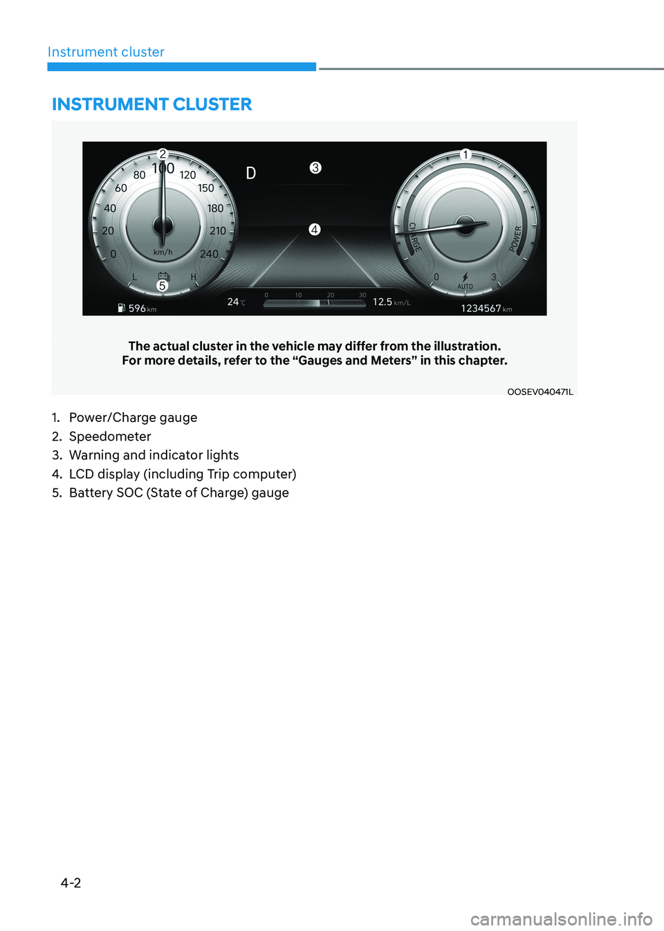
Instrument cluster
The actual cluster in the vehicle may differ from the illustration.
For more details, refer to the “Gauges and Meters” in this chapter.
OOSEV040471L
Instrument cluster
1. Power/Charge gauge
2. Speedometer
3. Warning and indicator lights
4. LCD display (including Trip computer)
5. Battery SOC (State of Charge) gauge
Page 146 of 548

04
4-3
Instrument cluster control
Instrument panel illumination
OOSEV040056L
When the vehicle’s position lights or
headlamps are on, press the illumination
control button to adjust the brightness of
the instrument panel illumination.
When pressing the illumination control
button, the interior switch illumination
intensity is also adjusted.
WARNING
Never adjust the instrument cluster
while driving. This could result in loss
of control and lead to an accident that
may cause death, serious injury, or
vehicle damage.
OCN7040019L
• The brightness of the instrument
panel illumination is displayed.
• If the brightness reaches the
maximum or minimum level, an alarm will sound.
Gauges and meters
Speedometer
OOSEV040472L
The speedometer indicates the speed of
the vehicle and is calibrated in kilometers
per hour (km/h).
Power/Charge gauge
OOSEV040474L
The Power/Charge gauge shows the
energy consumption rate of the vehicle
and the charge/discharge status of the
regenerative brakes. • POWER :
It shows the energy consumption rate
of the vehicle when driving uphill or
accelerating. The more electric energy is
used, the higher the gauge level. • CHARGE :
It shows the charging status of the
battery when it is being charged by the
regenerative brakes (decelerating or
driving on a downhill road). The more
electric energy is charged, the lower the
gauge level.
Page 150 of 548
04
4 -7
Warning and indicator lights
Information
Make sure that all warning lights are OFF
after starting the vehicle. If any light is still ON, this indicates a situation that needs attention.
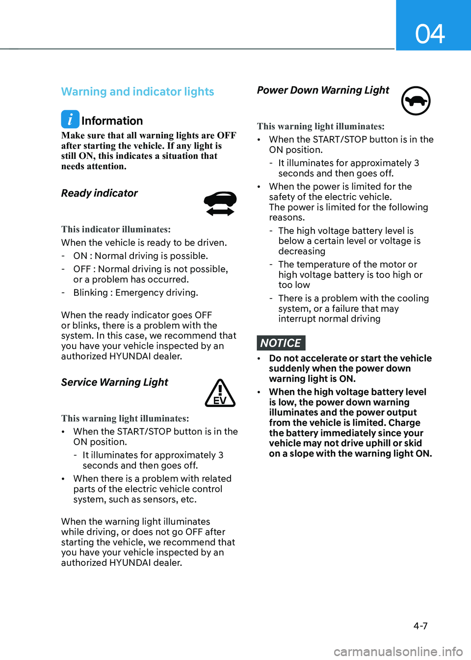
Ready indicator
This indicator illuminates:
When the vehicle is ready to be driven. - ON : Normal driving is possible.
- OFF : Normal driving is not possible, or a problem has occurred.
- Blinking : Emergency driving.
When the ready indicator goes OFF
or blinks, there is a problem with the
system. In this case, we recommend that
you have your vehicle inspected by an
authorized HYUNDAI dealer.
Service Warning Light
This warning light illuminates:
• When the START/STOP button is in the ON position.
- It illuminates for approximately 3 seconds and then goes off.
• When there is a problem with related
parts of the electric vehicle control
system, such as sensors, etc.
When the warning light illuminates
while driving, or does not go OFF after
starting the vehicle, we recommend that
you have your vehicle inspected by an
authorized HYUNDAI dealer.
Power Down Warning Light
This warning light illuminates:
• When the START/STOP button is in the ON position.
- It illuminates for approximately 3 seconds and then goes off.
• When the power is limited for the
safety of the electric vehicle.
The power is limited for the following
reasons.
- The high voltage battery level is below a certain level or voltage is
decreasing
- The temperature of the motor or high voltage battery is too high or
too low
- There is a problem with the cooling system, or a failure that may
interrupt normal driving
NOTICE
• Do not accelerate or start the vehicle
suddenly when the power down
warning light is ON.
• When the high voltage battery level
is low, the power down warning
illuminates and the power output
from the vehicle is limited. Charge
the battery immediately since your
vehicle may not drive uphill or skid
on a slope with the warning light ON.