2022 HYUNDAI IONIQ ELECTRIC stop start
[x] Cancel search: stop startPage 407 of 546
5-117
Driving your vehicle
5
Highway Driving Assist system helps
keep the vehicle between lanes,
maintain a distance with the vehicleahead, and automatically adjusts the
vehicle speed to the speed limit while
driving on the highway.Information
Highway Driving Assist system is available only on controlled access
road of certain highways.
❈
❈ Controlled access road indicates
roads with limited entrances and
exits that allow uninterrupted
high speed traffic flow. Only pas-
senger cars and motorcycles are
allowed on controlled access
roads.
Additional highways may be expanded by navigation updates.
System Setting and Operation
System setting
With the Engine Start/Stop buttonin the ON or START position,
Highway Driving Assist can be acti-
vated by selecting 'User Setting �
Driver Assistance �Driver Assist
� Highway Driving Assist' from the
Settings menu in the infotainment
system screen. Deselect the set-
ting to turn off the system.
If the engine is turned off then on again, the system maintains thelast setting.
i
HHIIGG HH WW AAYY DD RRIIVV IINN GG AA SSSSIISS TT (( HH DDAA )) SS YY SSTT EEMM (( IIFF EE QQ UUIIPP PP EEDD ))
Highway Driving Assist sys-
tem is not a substitute for safe
driving practices, but a con-
venience function. It is theresponsibility of the driver to
always be aware of the sur-
roundings and drive safely.
Highway Driving Assist sys-
tem relies entirely on the road
information provided by the
navigation system. It is theresponsibility of the driver to
follow traffic laws and avoidaccidents.
Turn off the Highway driving assist system when the vehi-
cle is being towed.
For your safety, please read
the owner's manual beforeusing the system.
WARNING
Available highway
(Controlled access road)
USA
Select Interstate Highway
and U.S. (Federal) and State Highways
CanadaSelect Provincial andTerritorial Highways
Page 437 of 546
6-2
The hazard warning flasher serves
as a warning to other drivers to exer-
cise extreme caution when approach-
ing, overtaking, or passing your vehi-
cle.
It should be used whenever emer- gency repairs are being made or
when the vehicle is stopped near the
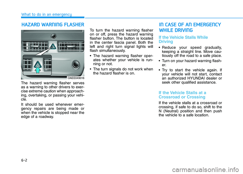
edge of a roadway. To turn the hazard warning flasher
on or off, press the hazard warning
flasher button. The button is located
in the center fascia panel. Both the
left and right turn signal lights will
flash simultaneously.
• The hazard warning flasher oper-
ates whether your vehicle is run- ning or not.
The turn signals do not work when the hazard flasher is on.
If the Vehicle Stalls While Driving
Reduce your speed gradually,keeping a straight line. Move cau-
tiously off the road to a safe place.
Turn on your hazard warning flash- er.
Try to start the vehicle again. If your vehicle will not start, contact
an authorized HYUNDAI dealer or
seek other qualified assistance.
If the Vehicle Stalls at a
Crossroad or Crossing
If the vehicle stalls at a crossroad or
crossing, if safe to do so, shift to the
N (Neutral) position and then push
the vehicle to a safe location.
HHAAZZAA RRDD WW AARRNN IINN GG FF LLAA SSHH EERR
What to do in an emergency
IINN CC AA SSEE OO FF AA NN EE MM EERR GG EENN CCYY
W
W HHIILL EE DD RRIIVV IINN GG
OAEE049016
Page 438 of 546
6-3
What to do in an emergency
If you Have a Flat Tire While Driving
If a tire goes flat while you are driving:
Take your foot off the acceleratorpedal and let the vehicle slow down
while driving straight ahead. Do not
apply the brakes immediately to
slow down the vehicle, but use the
paddle shifter (left side lever) to
increase regenerative braking con-
trol. Also, do not or attempt to pull
off the road as this may cause loss
of vehicle control resulting in an
accident. When the vehicle has
slowed to such a speed that it is
safe to do so, brake carefully and
pull off the road. Drive off the road
as far as possible and park on firm,
level ground. If you are on a divided
highway, do not park in the median
area between the two traffic lanes.
When the vehicle is stopped, press the hazard warning flasher button,
shift to P(Park), apply the parking
brake, and place the POWER but-ton in the OFF position. Have all passengers get out of the
vehicle. Be sure they all get out on
the side of the vehicle that is away
from traffic.
When changing a flat tire, follow the instructions provided later in
this chapter.
Confirm the EV Battery Is Not
Low on the Charge Gauge
Be sure the gear is in P (Park). The
vehicle starts only when the gear is
in P (Park).
Check the 12-volt battery connec- tions to be sure they are clean andtight.
Turn on the interior light. If the light dims or goes out when you operate
the starter, the battery is drained.
Do not push or pull the vehicle to
start it. This could cause damage to
your vehicle. See instructions for
"Jump Starting" provided in this
chapter.
6
II FF TT HH EE VV EEHH IICC LLEE WW IILL LL NN OO TT
S
S TT AA RRTT
Page 443 of 546
6-8
What to do in an emergencyT
T IIRR EE PP RR EESSSS UU RREE MM OONNIITT OO RRIINN GG SS YY SSTT EEMM (( TT PP MM SS)) (( IIFF EE QQ UUIIPP PPEEDD ))
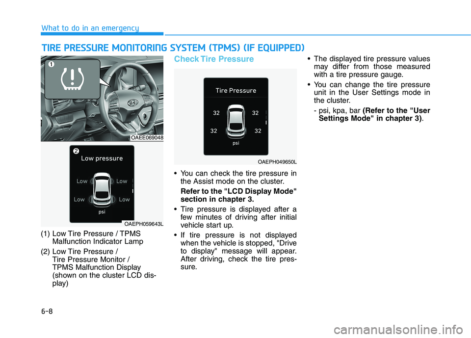
(1) Low Tire Pressure / TPMS
Malfunction Indicator Lamp
(2) Low Tire Pressure / Tire Pressure Monitor /
TPMS Malfunction Display
(shown on the cluster LCD dis-
play)
Check Tire Pressure
You can check the tire pressure inthe Assist mode on the cluster.
Refer to the "LCD Display Mode" section in chapter 3.
Tire pressure is displayed after a few minutes of driving after initial
vehicle start up.
If tire pressure is not displayed when the vehicle is stopped, "Drive
to display" message will appear.
After driving, check the tire pres-
sure. The displayed tire pressure values
may differ from those measured
with a tire pressure gauge.
You can change the tire pressure unit in the User Settings mode in
the cluster. - psi, kpa, bar (Refer to the "User
Settings Mode" in chapter 3) .
OAEE069048
OAEPH049650L
OAEPH059643L
Page 444 of 546
6-9
What to do in an emergency
6
Tire Pressure Monitoring System
Each tire, including the spare (if pro-
vided), should be checked monthlywhen cold and inflated to the inflation
pressure recommended by the vehi-
cle manufacturer on the vehicle plac-
ard or tire inflation pressure label. (If
your vehicle has tires of a different
size than the size indicated on the
vehicle placard or tire inflation pres-
sure label, you should determine the
proper tire inflation pressure for
those tires.)As an added safety feature, your
vehicle has been equipped with a tire
pressure monitoring system (TPMS)
that illuminates a low tire pressure
telltale when one or more of yourtires is significantly under-inflated.
Accordingly, when the low tire pres-
sure telltale illuminates, you should
stop and check your tires as soon as
possible, and inflate them to the
proper pressure. Driving on a signifi-cantly under-inflated tire causes the
tire to overheat and can lead to tire
failure. Under-inflation also reduces fuel effi-
ciency and tire tread life, and may
affect the vehicle’s handling and
stopping ability.
Please note that the TPMS is not a
substitute for proper tire mainte-
nance, and it is the driver’s responsi-bility to maintain correct tire pres-
sure, even if under-inflation has not
reached the level to trigger illumina-
tion of the TPMS low tire pressure
telltale.Your vehicle has also been equipped
with a TPMS malfunction indicator toindicate when the system is not
operating properly. The TPMS mal-function indicator is combined with
the low tire pressure telltale. Whenthe system detects a malfunction,
the telltale will flash for approximate-
ly one minute and then remain con-
tinuously illuminated. This sequence
will continue upon subsequent vehi-
cle start-ups as long as the malfunc-
tion exists. When the malfunction indicator is
illuminated, the system may not be
able to detect or signal low tire pres-
sure as intended. TPMS malfunc-
tions may occur for a variety of rea-
sons, including the installation of
replacement or alternate tires or
wheels on the vehicle that prevent
the TPMS from functioning properly.
Always check the TPMS malfunction telltale after replacing one or more
tires or wheels on your vehicle toensure that the replacement or alter-
nate tires and wheels allow the
TPMS to continue to function proper-
ly.
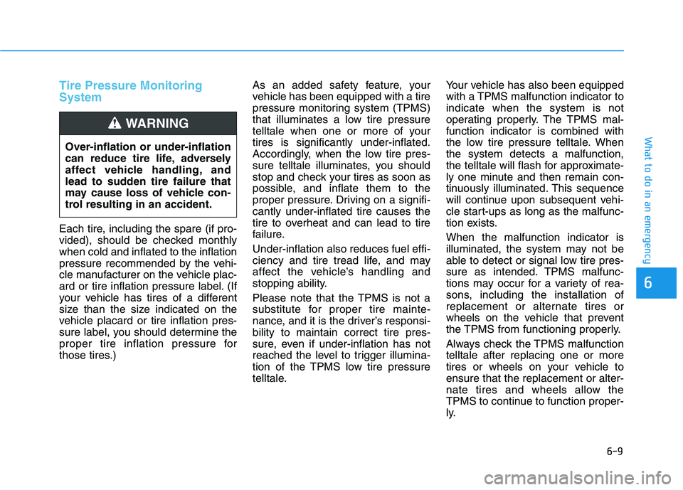
Over-inflation or under-inflation
can reduce tire life, adversely
affect vehicle handling, and
lead to sudden tire failure that
may cause loss of vehicle con-
trol resulting in an accident.
WARNING
Page 503 of 546
7-44
Maintenance
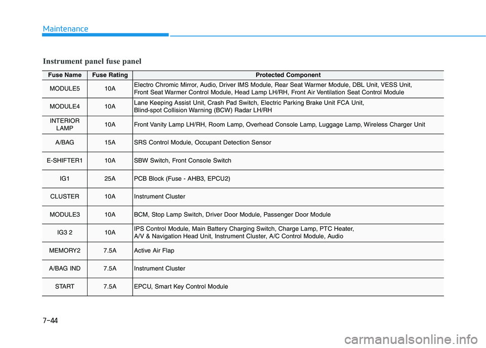
Fuse NameFuse RatingProtected Component
MODULE510AElectro Chromic Mirror, Audio, Driver IMS Module, Rear Seat Warmer Module, DBL Unit, VESS Unit,
Front Seat Warmer Control Module, Head Lamp LH/RH, Front Air Ventilation Seat Control Module
MODULE410ALane Keeping Assist Unit, Crash Pad Switch, Electric Parking Brake Unit FCA Unit,
Blind-spot Collision Warning (BCW) Radar LH/RH
INTERIORLAMP10AFront Vanity Lamp LH/RH, Room Lamp, Overhead Console Lamp, Luggage Lamp, Wireless Charger Unit
A/BAG 15ASRS Control Module, Occupant Detection Sensor
E-SHIFTER110ASBW Switch, Front Console Switch
IG125APCB Block (Fuse - AHB3, EPCU2)
CLUSTER10AInstrument Cluster
MODULE310ABCM, Stop Lamp Switch, Driver Door Module, Passenger Door Module
IG3 210AIPS Control Module, Main Battery Charging Switch, Charge Lamp, PTC Heater,
A/V & Navigation Head Unit, Instrument Cluster, A/C Control Module, Audio
MEMORY27.5AActive Air Flap
A/BAG IND7.5AInstrument Cluster
START7.5AEPCU, Smart Key Control Module
Instrument panel fuse panel
Page 505 of 546
7-46
Maintenance
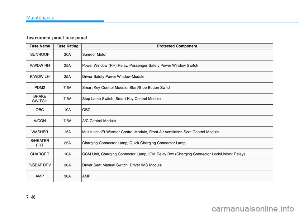
Fuse NameFuse RatingProtected Component
SUNROOF20ASunroof Motor
P/WDW RH25APower Window (RH) Relay, Passenger Safety Power Window Switch
P/WDW LH25ADriver Safety Power Window Module
PDM27.5ASmart Key Control Module, Start/Stop Button Switch
BRAKE
SWITCH7.5AStop Lamp Switch, Smart Key Control Module
OBC10AOBC
A/CON7.5AA/C Control Module
WASHER15AMultifunctioEt Warmer Control Module, Front Air Ventilation Seat Control Module
S/HEATER FRT25ACharging Connector Lamp, Quick Charging Connector Lamp
CHARGER10ACCM Unit, Charging Connector Lamp, ICM Relay Box (Charging Connector Lock/Unlock Relay)
P/SEAT DRV30ADriver Seat Manual Switch, Driver IMS Module
AMP30AAMP
Instrument panel fuse panel
Page 543 of 546
I-5
Lane Following Assist (LFA) ......................................5-110
LFA operation ...........................................................5-112
Limitations of the system .........................................5-115
Warning message ......................................................5-113
Lane Keeping Assist (LKA) ...........................................5-61 Limitations of the System ..........................................5-67
LKA operation ............................................................5-63
LKA system function change .....................................5-69
Warning light and message ........................................5-66
LCD Display ...................................................................3-73
LCD Display Control .................................................3-73
LCD display modes ....................................................3-74
Light ................................................................................3-91 Exterior Lights............................................................3-91
Interior Lights.............................................................3-99
Welcome System ......................................................3-102
Light bulbs ......................................................................7-52 Daytime Running Light (DRL) ..................................7-57
Headlamp, Parking Lamp, Turn Signal Lamp and Side Marker ..............................................................7-53
High Mounted Stop Light Replacement ...................7-60
Interior Light Bulb Replacement ...............................7-61
License Plate Light Bulb Replacement .....................7-61
Rear Combination Light Bulb Replacement .............7-58
Side Repeater Lamp Replacement .............................7-57 Maintenance services ........................................................7-4
Owner Maintenance Precautions..................................7-4
Owner's Responsibility.................................................7-4
Mirrors ............................................................................3-19 Inside Rearview Mirror ..............................................3-19
Reverse Parking Aid Function ..................................3-30
Side View Mirrors ....................................................3-27
Motor Compartment ..................................................1-6, 7-3
Motor number ...................................................................8-8
Owner maintenance ..........................................................7-5 Owner Maintenance Schedule......................................7-6
Paddle shifter (regenerative braking control) .................5-16 One Pedal Driving ......................................................5-17
Power button .....................................................................5-5 POWER Button Positions ............................................5-6
Starting the Vehicle ......................................................5-8
Turning Off the Vehicle................................................5-9
I
Index
LM
O
P