Page 59 of 546
H50
DDRRIIVV IINN GG EE LLEE CCTT RR IICC VV EEHH IICC LLEE (( CC OO NNTT..))
It shows the charging status of the
battery when it is being charged by
the regenerative brakes (decelerat-
ing or driving on a downhill road).
The more electric energy is charged,
the lower the gauge level.State of Charge (SOC) Gauge
for High Voltage Battery
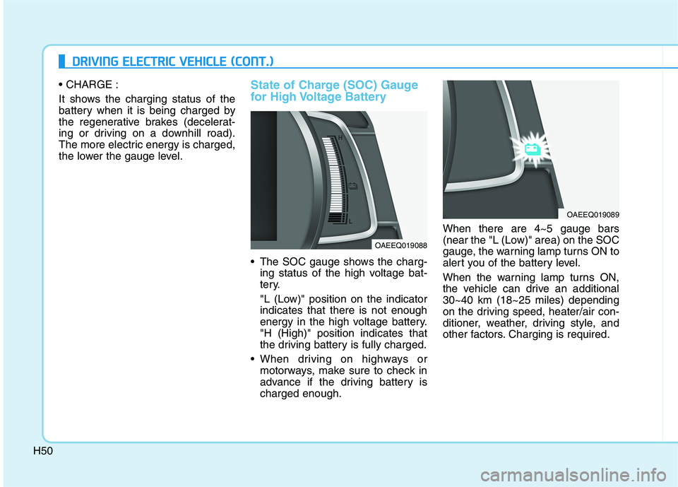
The SOC gauge shows the charg-
ing status of the high voltage bat-
tery.
"L (Low)" position on the indicator indicates that there is not enough
energy in the high voltage battery."H (High)" position indicates that
the driving battery is fully charged.
When driving on highways or motorways, make sure to check in
advance if the driving battery ischarged enough. When there are 4~5 gauge bars
(near the "L (Low)" area) on the SOC
gauge, the warning lamp turns ON to
alert you of the battery level.
When the warning lamp turns ON,
the vehicle can drive an additional30~40 km (18~25 miles) depending
on the driving speed, heater/air con-
ditioner, weather, driving style, and
other factors. Charging is required.
OAEEQ019088
OAEEQ019089
Page 62 of 546
H53
Regenerative BrakeWarning Light
This warning light illuminates :
When the regenerative brake does
not operate and the brake does not
perform well. This causes the Brake
Warning light (red) and Regenerative
Brake Warning Light (yellow) to illu-
minate simultaneously.
In this case, drive safely and have
your vehicle inspected by an author-
ized HYUNDAI dealer.
The operation of the brake pedal may
be more difficult than normal and the
braking distance can increase.
LCD Display Messages
Shift to P to charge
This message is displayed if you
connect the charging cable without
the gear in the P (Park) position.
Shift to P (Park) before connecting
the charging cable .
Remaining Time
This message is displayed to notifythe remaining time to charge the bat-
tery to the selected target battery
charge level.OAEPHQ049833L
(yellow)
OOSEV048133N/OOSEV048198N
■ AC charge■DC charge
Page 64 of 546
H55
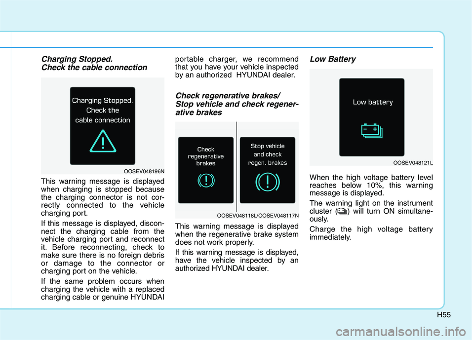
Charging Stopped.Check the cable connection
This warning message is displayed when charging is stopped becausethe charging connector is not cor-
rectly connected to the vehicle
charging port.
If this message is displayed, discon-
nect the charging cable from the
vehicle charging port and reconnect
it. Before reconnecting, check to
make sure there is no foreign debrisor damage to the connector or
charging port on the vehicle.
If the same problem occurs when
charging the vehicle with a replaced
charging cable or genuine HYUNDAI portable charger, we recommend
that you have your vehicle inspected
by an authorized HYUNDAI dealer.
Check regenerative brakes/
Stop vehicle and check regener-
ative brakes
This warning message is displayed
when the regenerative brake system
does not work properly.
If this warning message is displayed,
have the vehicle inspected by an
authorized HYUNDAI dealer.
Low Battery
When the high voltage battery level
reaches below 10%, this warning
message is displayed.
The warning light on the instrument
cluster ( ) will turn ON simultane-
ously.
Charge the high voltage battery
immediately.
OOSEV048121L
OOSEV048196N
OOSEV048118L/OOSEV048117N
Page 68 of 546
H59
Energy Flow
The electric vehicle system informs
the drivers its energy flow in various
operating modes. While driving, the
current energy flow is specified in 3
modes.
Vehicle Stop
The vehicle is stopped.
(No energy flow)
EV Propulsion
Only the motor power is used to drive
the vehicle.
(Battery ➞Wheel)
Regeneration
The high-voltage battery is charged
up by the regenerative brake system. (Wheel ➞Battery)
OAEPHQ049848LOAEPHQ049844L
OAEPHQ049843L
Page 70 of 546
H61
SSAA FFEE TT YY PP RR EECCAA UU TTIIOO NNSS FF OO RR EE LLEE CCTT RR IICC VV EEHH IICC LLEE
System Setting
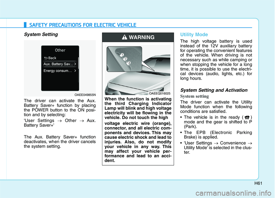
The driver can activate the Aux.
Battery Saver+ function by placing
the POWER button to the ON posi-
tion and by selecting: 'User Settings �Other � Aux.
Battery Saver+'
The Aux. Battery Saver+ function
deactivates, when the driver cancelsthe system setting.
Utility Mode
The high voltage battery is used
instead of the 12V auxiliary battery
for operating the convenient features
of the vehicle. When driving is not
necessary such as while camping or
when stopping the vehicle for a long
time, it is possible to use the electri-
cal devices (audio, lights, etc.) for
long hours.
System Setting and Activation
System setting
The driver can activate the Utility
Mode function when the followingconditions are satisfied.
The vehicle is in the ready ( ) mode and the gear is shifted to P
(Park).
The EPB (Electronic Parking Brake) is applied.
'User Settings �Convenience �
Utility Mode' is selected in the clus-
ter.When the function is activating
the third Charging Indicator
Lamp will blink and high voltage
electricity will be flowing in the
vehicle. Do not touch the high
voltage electric wire (orange),
connector, and all electric com-
ponents and devices. This may
cause electric shock and lead to
injuries. Also, do not modify
your vehicle in any way. This
may affect your vehicle per-
formance and lead to an acci-dent.
WARNING
OAEEQ016025OAEE049855N
Page 73 of 546
H64
Other Precautions for Electric
Vehicle
When you paint or apply heat treat-ment to the vehicle as a result of
an accident, the performance of
the high voltage battery can bereduced. If heat treatment is required, contact
an authorized HYUNDAI dealer.
When you clean the motor com- partment, do not use high pressure
water to wash. This may cause an
electric shock due to a discharge in
high voltage electricity, or damage
the vehicle's electric system.
Do not use, remodel, or install non- genuine parts. This may damage
the electric power system.
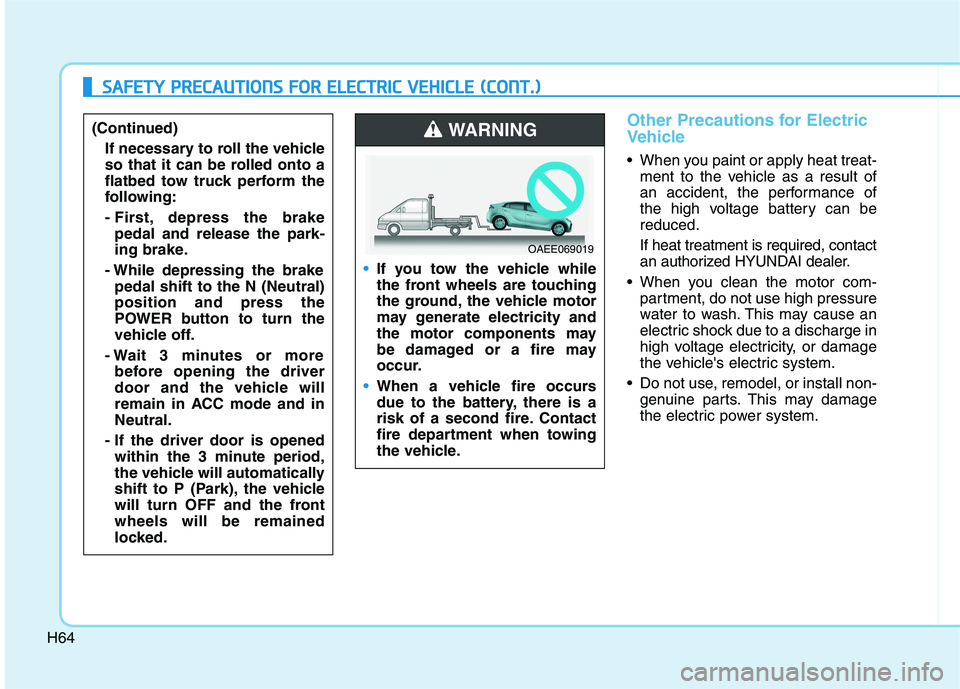
If you tow the vehicle while
the front wheels are touching
the ground, the vehicle motor
may generate electricity and
the motor components may
be damaged or a fire may
occur.
When a vehicle fire occurs
due to the battery, there is a
risk of a second fire. Contact
fire department when towing
the vehicle.
WARNING
OAEE069019
SSAA FFEE TT YY PP RR EECCAA UU TTIIOO NNSS FF OO RR EE LLEE CCTT RR IICC VV EEHH IICC LLEE (( CC OO NNTT..))
(Continued)
If necessary to roll the vehicle
so that it can be rolled onto a
flatbed tow truck perform the
following:
- First, depress the brakepedal and release the park-
ing brake.
- While depressing the brake pedal shift to the N (Neutral)position and press the
POWER button to turn the
vehicle off.
- Wait 3 minutes or more before opening the driver
door and the vehicle will
remain in ACC mode and inNeutral.
- If the driver door is opened within the 3 minute period,
the vehicle will automatically
shift to P (Park), the vehicle
will turn OFF and the frontwheels will be remained
locked.
Page 79 of 546
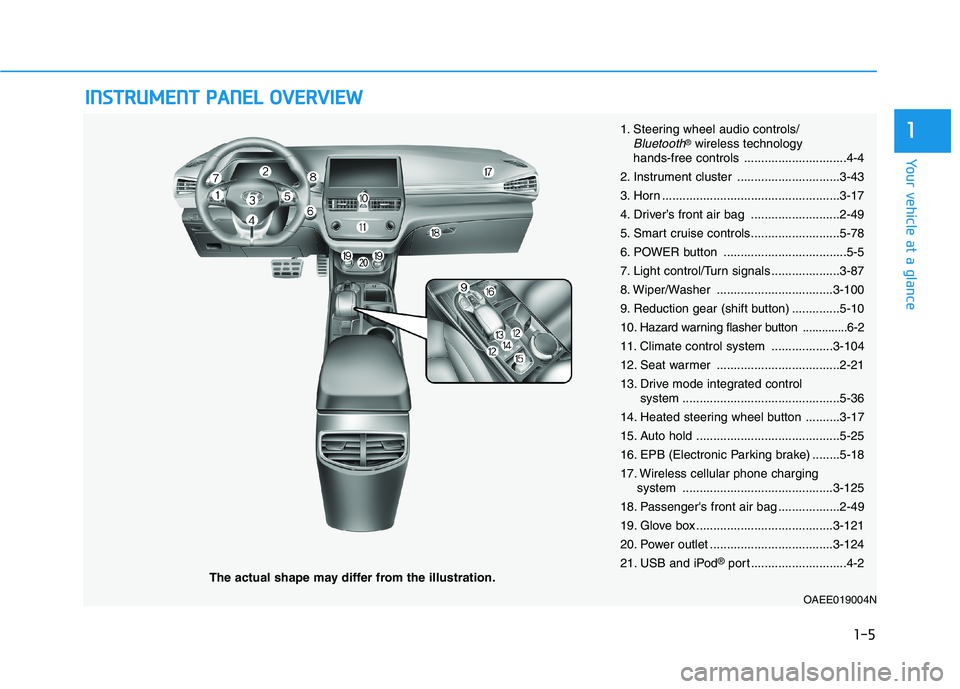
IINN SSTT RR UU MM EENN TT PP AA NN EELL OO VVEERR VV IIEE WW
The actual shape may differ from the illustration.
1-5
Your vehicle at a glance
11. Steering wheel audio controls/Bluetooth®wireless technology
hands-free controls ..............................4-4
2. Instrument cluster ..............................3-43
3. Horn ....................................................3-17
4. Driver’s front air bag ..........................2-49
5. Smart cruise controls..........................5-78
6. POWER button ....................................5-5
7. Light control/Turn signals ....................3-87
8. Wiper/Washer ..................................3-100
9. Reduction gear (shift button) ..............5-1010
. Hazard warning flasher button ..............6-2
11. Climate control system ..................3-104
12. Seat warmer ....................................2-21
13. Drive mode integrated control system ..............................................5-36
14. Heated steering wheel button ..........3-17
15. Auto hold ..........................................5-25
16. EPB (Electronic Parking brake) ........5-18
17. Wireless cellular phone charging system ............................................3-125
18. Passenger's front air bag ..................2-49
19. Glove box ........................................3-121
20. Power outlet ....................................3-124
21. USB and iPod ®
port ............................4-2
OAEE019004N
Page 80 of 546
1-6
Your vehicle at a glanceM
M OOTTOO RR CC OO MM PPAA RRTTMM EENN TT
1. Coolant reservoir ..............................7-12
2. Brake fluid reservoir ..........................7-16
3. Fuse box ...........................................7-44
4. Battery (12 volt) ................................7-24
5. Coolant cap.......................................7-13
6. Windshield washer fluid reservoir .....7-17
OAEE076001N
The actual motor compartment in the vehicle may differ from the illustration.