Page 608 of 647
09
9-51
Engine compartment fuse panel
(Engine room junction block)
OJX1099021OJX1099021
Inside the fuse/relay box cover, you can
find the fuse/relay label describing fuse/
relay names and ratings.
Information
Not all fuse panel descriptions in this
manual may be applicable to your vehicle;
the information is accurate at the time of
printing. When you inspect the fuse panel
in your vehicle, refer to the fuse panel
label.
OJK091055N
Page 609 of 647
Maintenance
9-52
Engine compartment fuse panel (Engine room junction block)
Type Fuse Name SymbolFuse
RatingCircuit Protected
MINEMDPS1
1MDPS100A MDPS Unit
ALT
ALT225A Alternator
MULTIE-CVVT1
E-CVVT140A [G4KR] E-CVVT Relay
OIL PUMP
OIL
PUMP50A Electronic Oil Pump
COOLING
FAN
COOLING
FAN100A Cooling Fan Motor
SBHEAD
LAMP LH
HEAD
LAMP
LH30A Head Lamp LH
START
START30A Start Relay
HEAD
LAMP RH
HEAD
LAMP
RH30A Head Lamp RH
MICROFUEL PUMP
FUEL
PUMP20A Fuel Pump Relay
4WD
4WD20A AWD ECU
ECU1
1ECU15A ECM
TCU1
1TCU20A TCM
HORN
HORN15A PCB Block (Horn Relay)
A/C1
A/C115A A/C Relay
E-CVVT2
E-CVVT220A [G4KR] ECM
E-CVVT3
E-CVVT320A [G4KR] ECM
Page 610 of 647

09
9-53
Engine compartment fuse panel (Engine room junction block)
Fuse Name SymbolFuse
RatingCircuit Protected
IG1IG130A IG1 Relay
ECU3
ECU330A Engine Control Realy
IG2
IG230A IG2 Relay
ACC
ACC30A ACC Relay
ECU2
ECU210A ECM
EWP
EWP20A Electronic Water Pump
MODULE
MODULE10ASmart Cruise Control Radar, Front Corner Radar LH/
RH, AWD ECU
MDPS2
MDPS210A MDPS Unit
IEB4
IEB410A IEB Unit
TCU2
TCU215A P/N Relay, TCM, Electronic Oil Pump
SENSOR3
SENSOR310A[G4KR] Oxygen Sensor (Up/Down), E/R Sub Junction
Block (PTC Heater1 Relay)
SENSOR2
SENSOR210A[G4KR] E/R Junction Block (A/C Relay), Oil Control
Valve (Exhaust), Oil Pump Solenoid Valve, Purge
Control Solenoid Valve, RCV Control Solenoid Valve,
Canister Close Valve
[G6DS] E/R Junction Block (A/C Relay), RCV Control
Solenoid Valve #1/#2, Purge Control Solenoid Valve,
Oil Pump Solenoid Valve, Oxygen Sensor #1~#4, Oil
Control Valve #1~#4, Canister Close Valve
SENSOR1
1SENSOR10A[G4KR] Injector #1~#4, E/R Junction Block (Fuel Pump
Relay)
[G6DS] Injector #1~#6 (MPI), E/R Junction Block (Fuel
Pump Relay)
IGN COIL
IGN COIL15A[G4KR] Ignition Coil #1~#4
[G6DS] Ignition Coil #1~#6
SENSOR4
SENSOR415A Cooling Fan Motor
ECU4
ECU420A ECM
WASHER
WASHER15A Washer Relay, E/R Junction Block (Washer RR Relay)
Page 611 of 647
Maintenance
9-54
Engine compartment fuse panel
(Engine room sub junction block)
OJK090036OJK090036
Inside the fuse/relay box cover, you can
find the fuse/relay label describing fuse/
relay names and ratings.
Information
Not all fuse panel descriptions in this
manual may be applicable to your vehicle;
the information is accurate at the time of
printing. When you inspect the fuse panel
in your vehicle, refer to the fuse panel
label.
OJK091056NOJK091056N
Page 612 of 647
09
9-55
Engine compartment fuse panel (Engine room sub junction block)
Type Fuse Name SymbolFuse
RatingCircuit Protected
SBPTC
HEATER1
PTC
HEATER130A [G4KR] PTC Heater 1 Relay
PTC
HEATER2
PTC
HEATER230A [G4KR] PTC Heater 2 Relay
PTC
HEATER3
PTC
HEATER330A [G4KR] PTC Heater 3 Relay
INVERTER
INVERTER30A AC Inverter
WIPER FRT
WIPER
FRT30A Wiper Motor
IEB 3
IEB340A IEB Unit
POWER
OUTLET 1
POWER
OUTLET140A Power Outlet1 Relay
REAR
HEATED
REAR
HEATED40A Rear Heated Relay
IEB 1
IEB160A IEB Unit
IEB 2
IEB260A IEB Unit
BLOWER
BLOWER40A Blower Relay
MICROPOWER
OUTLET 2
POWER
OUTLET220A Luggage Power Outlet
A/C 2
A/C210A A/C Control Module
HEATED
MIRROR
HEATED
MIRROR10AFront A/C Controller, Driver/Passenger
Power Outside Mirror
POWER
OUTLET 3
POWER
OUTLET320A Front Power Outlet
Page 617 of 647

Maintenance
9-60
Consult an authorized retailer of
Genesis Branded products to replace
most vehicle light bulbs. It is difficult
to replace vehicle light bulbs because
other parts of the vehicle must be
removed before you can get to the bulb.
This is especially true for removing the
headlamp assembly to get to the bulb(s).
Removing/installing the headlamp
assembly can result in damage to the
vehicle.
WARNING
• Prior to working on a light, depress
the foot brake, shift to P (Park), apply
the parking brake, press the Engine
Start/Stop button to the OFF position
and take the key with you when
leaving the vehicle to avoid sudden
movement of the vehicle and to
prevent possible electric shock.
• Be aware the bulbs may be hot and
may burn your fingers.
NOTICE
Be sure to replace the burned-out bulb
with one of the same wattage rating.
Otherwise, it may cause damage to the
fuse or electrical wiring system.
NOTICE
To prevent damage, do not clean the
headlamp lens with chemical solvents
or strong detergents.
Information - Headlamp
desiccant (if equipped)
This vehicle is equipped with desiccant to
reduce fogging inside the headlamp due
to moisture. The desiccant is consumable
and its performance may change based on
the used period or environment. If fogging
inside the headlamp due to moisture
continues for a long time, consult an
authorized retailer of Genesis Branded
products.
Information
The headlamp and tail lamp lenses could
appear frosty if the vehicle is washed after
driving or the vehicle is driven at night in
wet weather. This condition is caused by
temperature difference between the lamp
inside and outside and, it does not indicate
a problem with your vehicle. When
moisture condenses in the lamp, it will be
removed after driving with the headlamp
on. The removable level may differ
depending on lamp size, lamp position
and environmental condition. However, if
moisture is not removed, have the vehicle
inspected by an authorized retailer of
Genesis Branded products.
LIGHT BULBS
Page 623 of 647

Maintenance
9-66
NOTICE
• Do not use strong soap, chemical
detergents or hot water, and do not
wash the vehicle in direct sunlight
or when the body of the vehicle is
warm.
• Be careful when washing the side
windows of your vehicle.
• Especially, with high-pressure water,
water may leak through the windows
and wet the interior.
• To prevent damage to the plastic
parts, do not clean with chemical
solvents or strong detergents.
NOTICE
OJK090026OJK090026
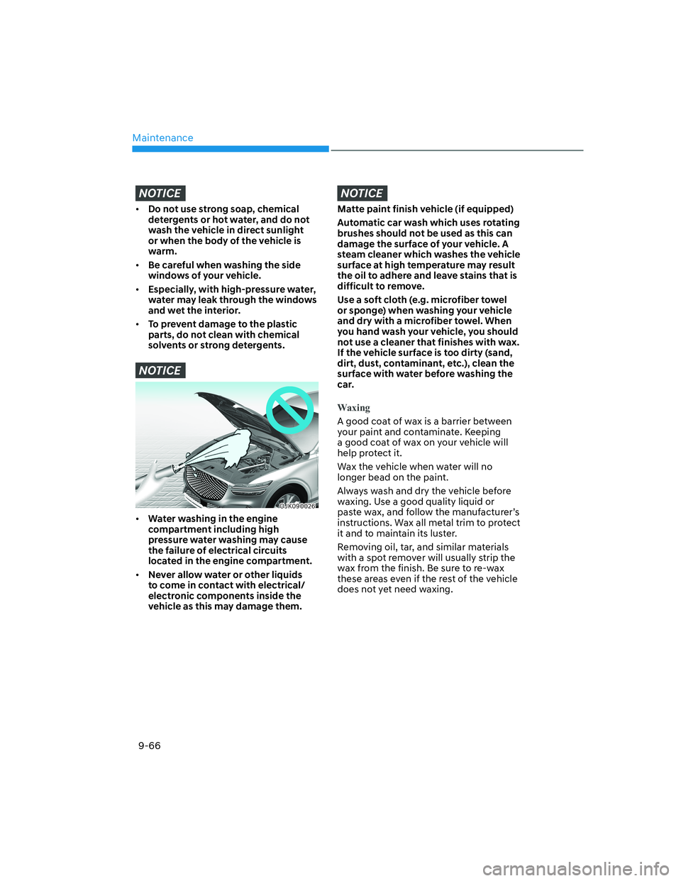
• Water washing in the engine
compartment including high
pressure water washing may cause
the failure of electrical circuits
located in the engine compartment.
• Never allow water or other liquids
to come in contact with electrical/
electronic components inside the
vehicle as this may damage them.
NOTICE
Matte paint finish vehicle (if equipped)
Automatic car wash which uses rotating
brushes should not be used as this can
damage the surface of your vehicle. A
steam cleaner which washes the vehicle
surface at high temperature may result
the oil to adhere and leave stains that is
difficult to remove.
Use a soft cloth (e.g. microfiber towel
or sponge) when washing your vehicle
and dry with a microfiber towel. When
you hand wash your vehicle, you should
not use a cleaner that finishes with wax.
If the vehicle surface is too dirty (sand,
dirt, dust, contaminant, etc.), clean the
surface with water before washing the
car.
Waxing
A good coat of wax is a barrier between
your paint and contaminate. Keeping
a good coat of wax on your vehicle will
help protect it.
Wax the vehicle when water will no
longer bead on the paint.
Always wash and dry the vehicle before
waxing. Use a good quality liquid or
paste wax, and follow the manufacturer’s
instructions. Wax all metal trim to protect
it and to maintain its luster.
Removing oil, tar, and similar materials
with a spot remover will usually strip the
wax from the finish. Be sure to re-wax
these areas even if the rest of the vehicle
does not yet need waxing.
Page 630 of 647

09
9-73
The emission control system of your
vehicle is covered by a written limited
warranty. Please see the warranty
information contained in the Owner’s
Handbook & Warranty Information
booklet in your vehicle.
Your vehicle is equipped with an
emission control system to meet all
applicable emission regulations. There
are three emission control systems, as
follows.
(1) Crankcase emission control system
(2) Evaporative emission control system
(3) Exhaust emission control system
In order to ensure the proper function
of the emission control systems, it
is recommended that you have your
vehicle inspected and maintained by an
authorized retailer of Genesis Branded
products in accordance with the
maintenance schedule in this manual.
NOTICE
For the Inspection and Maintenance
Test (with Electronic Stability Control
(ESC) system)
• To prevent the vehicle from misfiring
during dynamometer testing, turn
the Electronic Stability Control
(ESC) system off by pressing the ESC
switch (ESC OFF light illuminated).
• After dynamometer testing is
completed, turn the ESC system back
on by pressing the ESC switch again.
1. Crankcase Emission Control
System
The positive crankcase ventilation system
is employed to prevent air pollution
caused by blow-by gases being emitted
from the crankcase. This system supplies
fresh filtered air to the crankcase through
the air intake hose. Inside the crankcase,
the fresh air mixes with blow-by gases,
which then pass through the PCV valve
into the induction system.
2. Evaporative Emission Control
System including Onboard
Refueling Vapor Recovery
(ORVR)
The Evaporative Emission Control System
is designed to prevent fuel vapors from
escaping into the atmosphere. The
ORVR system is designed to allow the
vapors from the fuel tank to be loaded
into a canister while refueling at the gas
station, preventing the escape of fuel
vapors into the atmosphere.
Canister
Fuel vapors generated inside the fuel
tank are absorbed and stored in the
onboard canister. When the engine is
running, the fuel vapors absorbed in the
canister are drawn into the surge tank
through the purge control solenoid valve.
Purge Control Solenoid Valve (PCSV)
The purge control solenoid valve
is controlled by the Engine Control
Module (ECM); when the engine coolant
temperature is low during idling, the
PCSV closes so that evaporated fuel
is not taken into the engine. After the
engine warms-up during ordinary
driving, the PCSV opens to introduce
evaporated fuel to the engine.
EMISSION CONTROL SYSTEM