Page 728 of 782
Continued727
uuIf a Tire Goes Flat uChanging a Flat Tire
Handling the Unexpected
1. Remove the wheel nuts and flat tire.
2. Wipe the mounting surfaces of the wheel
with a clean cloth.
3. Mount the compact spare tire.
4. Screw the wheel nuts until they touch the
lips around the mounting holes, then stop
rotating.
■Replacing the Flat Tire1Replacing the Flat Tire
Do not over tighten the wheel nuts by applying extra
torque using your foot or a pipe.
22 US ODYSSEY-31THR6400.book 727 ページ 2020年11月16日 月曜日 午後1時41分
Page 729 of 782
uuIf a Tire Goes Flat uChanging a Flat Tire
728
Handling the Unexpected
5. Lower the vehicle and remove the jack.
Tighten the wheel nuts in the order
indicated in the image. Go around,
tightening the nuts, two to three times in
this order.
Wheel nut torque:
94 lbf∙ft (127 N∙m, 13 kgf∙m)
The storage bag, bracket, mounting wing bolt
(A) and mounting wing bolt (B) are in the tool
case.
1. Put the flat tire in the storage bag provided
with your vehicle.
■Storing the Flat Tire1Storing the Flat Tire
3WARNING
Loose items can fly around the interior in a
crash and can seriously injure the
occupants.
Store the wheel, jack, and tools securely
before driving.
Bracket
Mounting Wing Bolt (A)
Mounting Wing Bolt (B)Storage Bag
22 US ODYSSEY-31THR6400.book 728 ページ 2020年11月16日 月曜日 午後1時41分
Page 730 of 782
729
uuIf a Tire Goes Flat uChanging a Flat Tire
Continued
Handling the Unexpected
2. Pull down the U-sh aped carpet piece.
3. Remove the plastic screw with a coin.
4. Install the bracket an d the mounting wing
bolt (A) on the attachment point, and
tighten the bolt.
5. Install the flat tire on the bracket with the
inside of the wheel facing toward you.
6. Install the mounting wing bolt (B) to the
bracket through one of the five wheel nut
holes, and tighten the bolt.
u Poke a hole in the storage bag as
needed.
Plastic Screw
Carpet Piece
Mounting
Wing Bolt
(A)
Bracket
Mounting Wing Bolt (B)
22 US ODYSSEY-31THR6400.book 729 ページ 2020年11月16日 月曜日 午後1時41分
Page 731 of 782
730
uuIf a Tire Goes Flat uChanging a Flat Tire
Handling the Unexpected
■Storing a flat tire on the folded third row seat
1.Turn over the flap on the left side of the
cargo area floor.
2. Pull down the U-shaped carpet piece and
remove the plastic screw with a coin.
3. Place the flat tire face down on the
attachment point.
4. Put the tire mounting wing bolt (B) in the
attachment point through one of the five
wheel nut holes, and tighten the bolt.
u Poke a hole in the storage bag as
needed.
Plastic Screw
Mounting
Wing Bolt
(B)
22 US ODYSSEY-31THR6400.book 730 ページ 2020年11月16日 月曜日 午後1時41分
Page 732 of 782

731
uuIf a Tire Goes Flat uChanging a Flat Tire
Handling the Unexpected
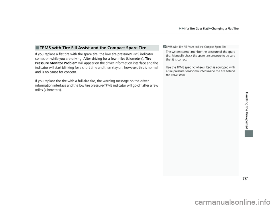
If you replace a flat tire with the spare tire, the low tire pressure/TPMS indicator
comes on while you are driving. After driving for a few miles (kilometers), Tire
Pressure Monitor Problem will appear on the driver information interface and the
indicator will start blinking fo r a short time and then stay on; however, this is normal
and is no cause for concern.
If you replace the tire with a full-size tire, the warning message on the driver
information interface and the low tire pre ssure/TPMS indicator will go off after a few
miles (kilometers).
■TPMS with Tire Fill Assist and the Compact Spare Tire1 TPMS with Tire Fill Assist and the Compact Spare Tire
The system cannot monitor th e pressure of the spare
tire. Manually check the spare tire pressure to be sure
that it is correct.
Use the TPMS specific wheels. Each is equipped with
a tire pressure sensor mount ed inside the tire behind
the valve stem.
22 US ODYSSEY-31THR6400.book 731 ページ 2020年11月16日 月曜日 午後1時41分
Page 735 of 782

734
uuEngine Does Not Start uEmergency Engine Stop
Handling the Unexpected
Emergency Engine Stop
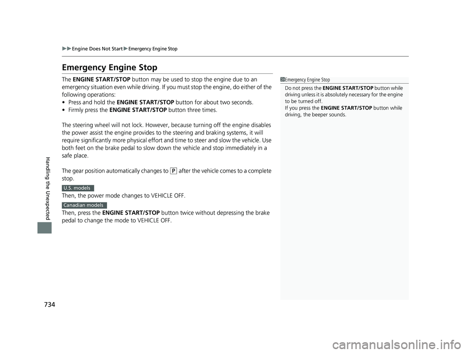
The ENGINE START/STOP button may be used to stop the engine due to an
emergency situation even while driving. If you must stop the engine, do either of the
following operations:
• Press and hold the ENGINE START/STOP button for about two seconds.
• Firmly press the ENGINE START/STOP button three times.
The steering wheel will not lock. However, because turning off the engine disables
the power assist the engine provides to the steering and braking systems, it will
require significantly more physical effort an d time to steer and slow the vehicle. Use
both feet on the brake pedal to slow down the vehicle and stop immediately in a
safe place.
The gear position automatically changes to
(P after the vehicle comes to a complete
stop.
Then, the power mode changes to VEHICLE OFF.
Then, press the ENGINE START/STOP button twice without depressing the brake
pedal to change the mode to VEHICLE OFF.
1 Emergency Engine Stop
Do not press the ENGINE START/STOP button while
driving unless it is absolute ly necessary for the engine
to be turned off.
If you press the ENGINE START/STOP button while
driving, the beeper sounds.
U.S. models
Canadian models
22 US ODYSSEY-31THR6400.book 734 ページ 2020年11月16日 月曜日 午後1時41分
Page 748 of 782

747
uuFuses uFuse Locations
Continued
Handling the Unexpected
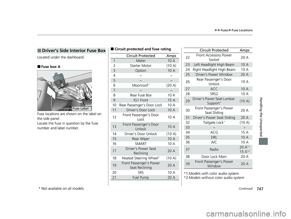
Located under the dashboard.
■Fuse box A
Fuse locations are shown on the label on
the side panel.
Locate the fuse in question by the fuse
number and label number.
■Driver’s Side Interior Fuse Box
Fuse Label
■Circuit protected and fuse rating
Circuit ProtectedAmps
1Meter10 A
2Starter Motor(10 A)
3Option10 A
4−−
5−−
6Moonroof*(20 A)
7−−
8Rear Fuse Box10 A
9IG1 Front15 A
10 Rear Passenger’s Door Lock 10 A
11Driver’s Door Lock10 A
12 Front Passenger’s Door
Lock 10 A
13Front Passenger’s Door
Unlock10 A
14 Driver’s Door Unlock (10 A)
15Rear Wiper10 A
16 SMART 10 A
17Driver’s Power Seat Reclining20 A
18 Heated Steering Wheel
*(10 A)
19Front Passenger’s Power Seat Reclining20 A
20 SRS 10 A
21Fuel Pump20 A*1:Models with color audio system
*2:Models without color audio system22
Front Accessory Power
Socket 20 A
23Left Headlight High Beam10 A
24 Right Headlight High Beam 10 A
25Driver’s Power Window20 A
26 Rear Passenger’s Door
Unlock 10 A
27ACC10 A
28 SRS2 10 A
29Driver’s Power Seat Lumbar Support*(10 A)
30 Front Passenger’s Power
Seat Sliding 20 A
31Driver’s Power Seat Sliding20 A
32 Tailgate Lock*(10 A)
33−−
34 ACG 15 A
35DRL10 A
36 A/C 10 A
37Radio20 A*1
15 A*2
38 Door Lock Main 20 A
39Front Passenger’s Power Window20 A
Circuit ProtectedAmps
* Not available on all models
22 US ODYSSEY-31THR6400.book 747 ページ 2020年11月16日 月曜日 午後1時41分
Page 762 of 782

761
uuSpecifications u
Information
■
Brake Fluid
■ Automatic Tran smission Fluid
SpecifiedHonda Heavy Duty Brake Fluid DOT 3
SpecifiedHonda ATF-Type 2
■
Engine Oil
■ Engine Coolant
Recommended·Genuine Honda Motor Oil 0W-20
·API Premium-grade 0W-20 detergent oil
Capacity Change 5.4 US qt (5.1 L)
Change
including
filter
5.7 US qt (5.4 L)
SpecifiedHonda Long-Life Antifreeze/Coolant Type2
Ratio 50/50 with distilled water
Capacity1.69 US gal (6.38 L)
(change including the remaining 0.19 US gal
(0.73 L) in the reserve tank)
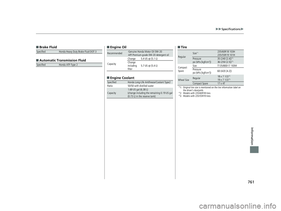
■ Tire
*1: Original tire size is mentioned on the tire information label on
the driver’s doorjamb.
*2: Models with 235/60R18 tires
*3: Models with 235/55R19 tires
RegularSize*1235/60R18 103H
235/55R19 101H
Pressure
psi (kPa [kgf/cm2])35 (240 [2.4])*2
36 (250 [2.5])*3
Compact
Spare Size
T135/80D17 103M
Pressure
psi (kPa [kgf/cm
2]) 60 (420 [4.2])
Wheel SizeRegular18 x 7 1/2J*2
19 x 7 1/2J*3
Compact Spare17 x 4T
22 US ODYSSEY-31THR6400.book 761 ページ 2020年11月16日 月曜日 午後1時41分