2022 FORD F-350 instrument cluster
[x] Cancel search: instrument clusterPage 311 of 740

PRE-COLLISION ASSIST –
FREQUENTLY ASKED QUESTIONS
Camera Troubleshooting
The windshield in front of the camera
is dirty or obstructed.
Clean the outside of the windshield in
front of the camera.
The windshield in front of the camera
is clean, but the message remains in
the instrument cluster display. Wait a short time. It could take several
minutes for the camera to detect that
there is no obstruction.
Radar Troubleshooting (If Equipped)
The surface of the radar in the grille is
dirty or obstructed. Clean the grille surface in front of the
radar or remove the object causing the
obstruction.
The surface of the radar in the grille is
clean, but the message remains in the
instrument cluster display. Wait a short time. It could take several
minutes for the radar to detect that
there is no obstruction.
Heavy rain, spray or fog is interfering
with the radar signals. The pre-collision assist system is
temporarily disabled. Pre-collision
assist reactivates a short time after
the weather conditions improve.
Swirling water or snow or ice on the
surface of the road is interfering with
the radar signals. The pre-collision assist system is
temporarily disabled. Pre-collision
assist reactivates a short time after
the weather conditions improve. Radar is out of alignment due to a
front-end impact.
Have your vehicle serviced to have the
radar checked for proper coverage and
operation.
308
2022 Super Duty (TFE) Canada/United States of America, enUSA, Edition date: 202103, First-Printing Pre-Collision Assist
(If Equipped)
Page 313 of 740

SWITCHING DRIVER ALERT ON
AND OFF - VEHICLES WITH: 4.2
INCH SCREEN
To switch the system on or off, use the
instrument cluster display:
1. Select Driver Assist.
2. Select
Driver Alert.
3. Switch the feature on or off.
Note: The system remains on or off
depending on how it was last set.
Resetting Driver Alert
You can reset the system by either:
• Switching the ignition off and on.
• Stopping the vehicle and then opening
and closing the driver door. SWITCHING DRIVER ALERT ON
AND OFF - VEHICLES WITH: 8
INCH SCREEN
To switch the system on or off, use the
instrument cluster display:
1. Select
Driver Assist.
2. Select
Driver Alert.
3. Switch the feature on or off.
Note: The system remains on or off
depending on how it was last set.
Resetting Driver Alert
You can reset the system by either:
• Switching the ignition off and on.
• Stopping the vehicle and then opening
and closing the driver door.
DRIVER ALERT – TROUBLESHOOTING
DRIVER ALERT – INFORMATION MESSAGES Action
Message
Stop and rest as soon as it is safe to do so.
Driver Alert Warning Rest Now
Take a rest soon.
Driver Alert Warning Rest Suggested
310
2022 Super Duty (TFE) Canada/United States of America, enUSA, Edition date: 202103, First-Printing Driver Alert
Page 328 of 740

Website
Market
ht tp s:/ /
www .fl e e t.f or d . c om/
t o wing-g uide s/United States of
America
ht tp s:/ /
www .fl e e t.f or d . c a/
t o wing-g uide s/Canada
FIFTH-WHEEL TRAILER HITCH
Your vehicle has a fifth-wheel prep
package. This package enables your
vehicle to accept certain fifth-wheel trailer
hitches and gooseneck ball hitches. The
fifth-wheel trailer hitch attaches to the four
mounting pads in the pick-up bed. A 7-pin
trailer wiring connector could be in the bed
as well. The gooseneck ball hitch is a
separate mounting pad from the
fifth-wheel hitch in the center of the bed.
Shorter pick-up boxes provide less
clearance between the cab and the
fifth-wheel and gooseneck trailer
compared to longer box pick-ups. When
selecting a trailer and tow vehicle, it is
critical to check that this combination
provides clearance between the front of
the trailer and tow vehicle for turns up to
90°. Failure to follow this recommendation
could result in the trailer contacting the
cab of the tow vehicle during tight turns
that are typical during low-speed parking
and turning maneuvers. This contact could
result in damage to the trailer and tow
vehicle.
Note: Contact an authorized dealer to
purchase gooseneck and fifth-wheel hitches
that are compatible with your vehicle.
Note: The mounting pads in the bed are
specifically designed for certain fifth-wheel
trailer hitches and gooseneck ball hitches.
Do not use these mounting pads for other
purposes. CONNECTING A TRAILER
Recognizing a Trailer
1.
Attach the trailer and wiring connector
to your vehicle.
2. Switch on your vehicle.
3. Set up a profile for the trailer using the
instrument cluster display.
Note: If your vehicle does not recognize the
trailer, press and hold the brake pedal for a
few seconds.
Note: Trailer profiles store trailer types,
dimensions, preferences, trailer specific
mileage and fuel economy.
Note: Disabling the trailer detection
notification makes the default trailer profile
active when a connection is detected. When attaching the trailer wiring connector
to your vehicle, only use a proper fitting
connector that works with the vehicle and
trailer functions.
325
2022 Super Duty (TFE) Canada/United States of America, enUSA, Edition date: 202103, First-Printing Connecting a TrailerE163167
Page 338 of 740

6. If the trailer wheels lock up, indicated
by squealing tires, reduce the gain
setting. If the trailer wheels turn freely,
increase the gain setting. Repeat Steps
5 and 6 until the gain setting is at a
point just below trailer wheel lock-up.
If towing a heavier trailer, trailer wheel
lock-up may not be attainable even
with the maximum gain setting of 10.
Note: Only perform this procedure at
speeds of approximately 20– 25 mph
(30–40 km/h).
Note: The trailer brake controller reduces
output at vehicle speeds below
11 mph
(18 km/h) so that trailer and vehicle braking
is not jerky or harsh. This feature is only
available when applying the brakes using
your vehicle's brake pedal, not the
controller.
Note: Your vehicle's brake system and the
trailer brake system work independently of
each other. Changing the gain setting on the
controller does not affect the operation of
your vehicle's brakes whether you attach a
trailer or not.
Note: With the proper electrical connection,
pressing your vehicle brake pedal or using
the manual control lever illuminates both
trailer and vehicle brake lamps.
Note: When you switch the engine off, the
controller output is disabled and the display
and module shut down. The controller
module and display turn on when you switch
the ignition on. Adjusting the Trailer Brake Gain
Increase or decrease the amount
of gain in set increments.
A
Slide the control to engage the
trailer brakes.
B
Note: Adjust gain setting before using the
trailer brake controller for the first time.
Note: The gain should be set to provide the
maximum trailer braking assistance while
making sure the trailer wheels do not lock
when using the brakes. Locked trailer wheels
may lead to trailer instability.
Note: Setting adjustments are saved when
a trailer profile is selected.
ADJUSTING THE INTEGRATED
TRAILER BRAKE CONTROLLER
MODE
Select the correct integrated trailer brake
controller mode option using the
instrument cluster display.
Note: Trailer brake gain settings are saved
to the active trailer profile.
335
2022 Super Duty (TFE) Canada/United States of America, enUSA, Edition date: 202103, First-Printing Integrated Trailer Brake Controller
(If Equipped)E333154
Page 339 of 740

Selecting the Trailer Brake Type
Use the instrument cluster display controls
on the steering wheel to select the correct
setting for your trailer.
Note:
Select Default
Electric/Surge/None if the trailer has
electric, surge or no brakes. Selecting the Trailer Brake Effort
Select the correct setting for your trailer.
Note:
Select a different setting if your
trailer's brakes require more initial voltage,
or you prefer more aggressive trailer braking.
INTEGRATED TRAILER BRAKE CONTROLLER –
TROUBLESHOOTING
INTEGRATED TRAILER BRAKE CONTROLLER – INFORMATION
MESSAGES Action
Message
The system detects a correct trailer
connection during a given ignition cycle.
Trailer Connected
The system detects the trailer wiring
connection is disconnected, during a given ignition cycle.
Trailer Disconnected
The system detects an electrical fault inthe trailer brake circuit. If this message
appears without a trailer attached, see your authorized dealer. If a trailer is attached, inspect and repair the trailer wiring.
Trailer Wiring Fault
Displays the current gain setting for thetrailer brake.
Trailer Brake Gain: {trailer gain value:#0.0}
Displays the current gain setting for the
trailer brake when you do not have a trailer connected.
Trailer Brake Gain: {trailer gain value:#0.0}
No Trailer
336
2022 Super Duty (TFE) Canada/United States of America, enUSA, Edition date: 202103, First-Printing Integrated Trailer Brake Controller
(If Equipped)
Page 343 of 740

Positioning the Trailer
Hitch the trailer to your vehicle and
connect the electrical wiring harness.
Check to make sure that the wiring is
working. See Connecting a Trailer (page
323).
Park your vehicle and hitched trailer on a
level surface.
For best results, make sure that your trailer
rides level with the ground when you hitch
your vehicle. See
Connecting a Trailer
(page 323). Make sure that the trailer and your vehicle
are in line with each other. You can do this
by putting the transmission in drive (D) and
pulling straight forward.
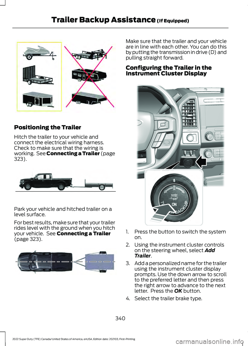
Configuring the Trailer in the
Instrument Cluster Display
1. Press the button to switch the system
on.
2. Using the instrument cluster controls on the steering wheel, select
Add
Trailer.
3. Add a personalized name for the trailer
using the instrument cluster display
prompts. Use the down arrow to scroll
to the preferred letter and then press
the right arrow to advance to the next
letter. Press the
OK button.
4. Select the trailer brake type.
340
2022 Super Duty (TFE) Canada/United States of America, enUSA, Edition date: 202103, First-Printing Trailer Backup Assistance
(If Equipped)E209766 E209759 E209760 E318266
Page 345 of 740

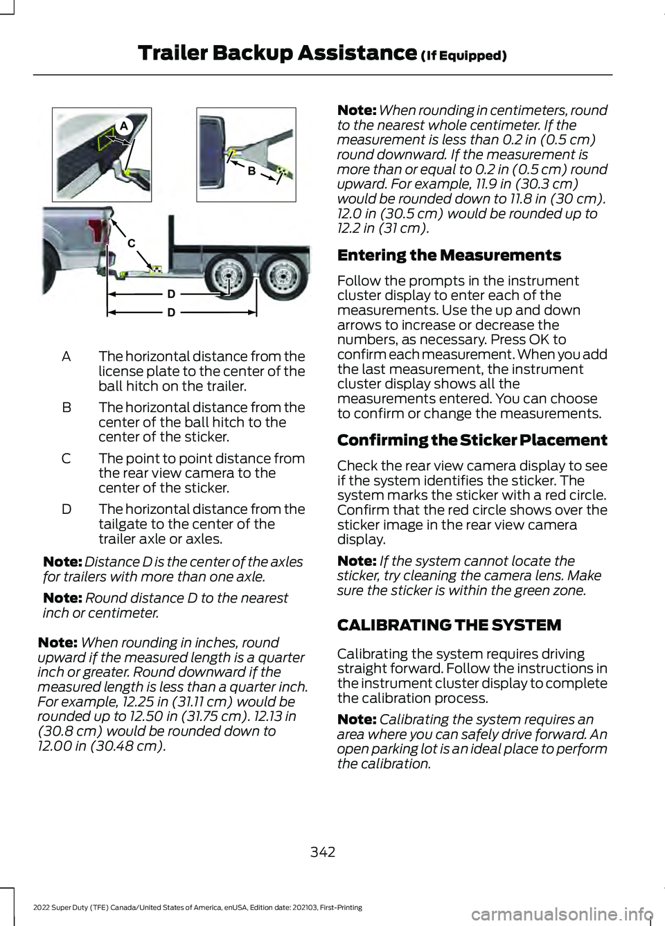
The horizontal distance from the
license plate to the center of the
ball hitch on the trailer.
A
The horizontal distance from the
center of the ball hitch to the
center of the sticker.
B
The point to point distance from
the rear view camera to the
center of the sticker.
C
The horizontal distance from the
tailgate to the center of the
trailer axle or axles.
D
Note: Distance D is the center of the axles
for trailers with more than one axle.
Note: Round distance D to the nearest
inch or centimeter.
Note: When rounding in inches, round
upward if the measured length is a quarter
inch or greater. Round downward if the
measured length is less than a quarter inch.
For example, 12.25 in (31.11 cm) would be
rounded up to 12.50 in (31.75 cm). 12.13 in
(30.8 cm) would be rounded down to
12.00 in (30.48 cm). Note:
When rounding in centimeters, round
to the nearest whole centimeter. If the
measurement is less than
0.2 in (0.5 cm)
round downward. If the measurement is
more than or equal to 0.2 in (0.5 cm) round
upward. For example, 11.9 in (30.3 cm)
would be rounded down to
11.8 in (30 cm).
12.0 in (30.5 cm) would be rounded up to
12.2 in (31 cm).
Entering the Measurements
Follow the prompts in the instrument
cluster display to enter each of the
measurements. Use the up and down
arrows to increase or decrease the
numbers, as necessary. Press OK to
confirm each measurement. When you add
the last measurement, the instrument
cluster display shows all the
measurements entered. You can choose
to confirm or change the measurements.
Confirming the Sticker Placement
Check the rear view camera display to see
if the system identifies the sticker. The
system marks the sticker with a red circle.
Confirm that the red circle shows over the
sticker image in the rear view camera
display.
Note: If the system cannot locate the
sticker, try cleaning the camera lens. Make
sure the sticker is within the green zone.
CALIBRATING THE SYSTEM
Calibrating the system requires driving
straight forward. Follow the instructions in
the instrument cluster display to complete
the calibration process.
Note: Calibrating the system requires an
area where you can safely drive forward. An
open parking lot is an ideal place to perform
the calibration.
342
2022 Super Duty (TFE) Canada/United States of America, enUSA, Edition date: 202103, First-Printing Trailer Backup Assistance
(If Equipped)A
B
C
D
DE209806
Page 346 of 740

Note:
Keep the steering wheel straight
when instructed to by the instrument cluster
display. If the steering wheel is in a turned
position during this instruction, the
calibration pauses.
Note: The system is designed to work with
drawbars that have a license plate to hitch
ball center measurement of 9– 20 in
(23–52 cm) when installed. Do not attempt
to use drawbars that have a length outside
of this range as the system performance
degrades and could cause improper system
function.
Note: The instrument cluster display shows
if you are going too slow or fast. Calibration
pauses if the speed is outside the required
range of
4– 24 mph (6– 39 km/h).
Note: For best results, do not calibrate the
system at night when calibrating the system
with the sticker.
SETTING UP THE TRAILER
BACKUP ASSISTANCE FOR A
FIFTH-WHEEL OR GOOSENECK
TRAILER
CONFIGURING THE TRAILER
You must configure a trailer in the system
to use trailer backup assistance. This is a
one-time setup process and the trailer
information is saved in the system for the
next time you use that trailer.
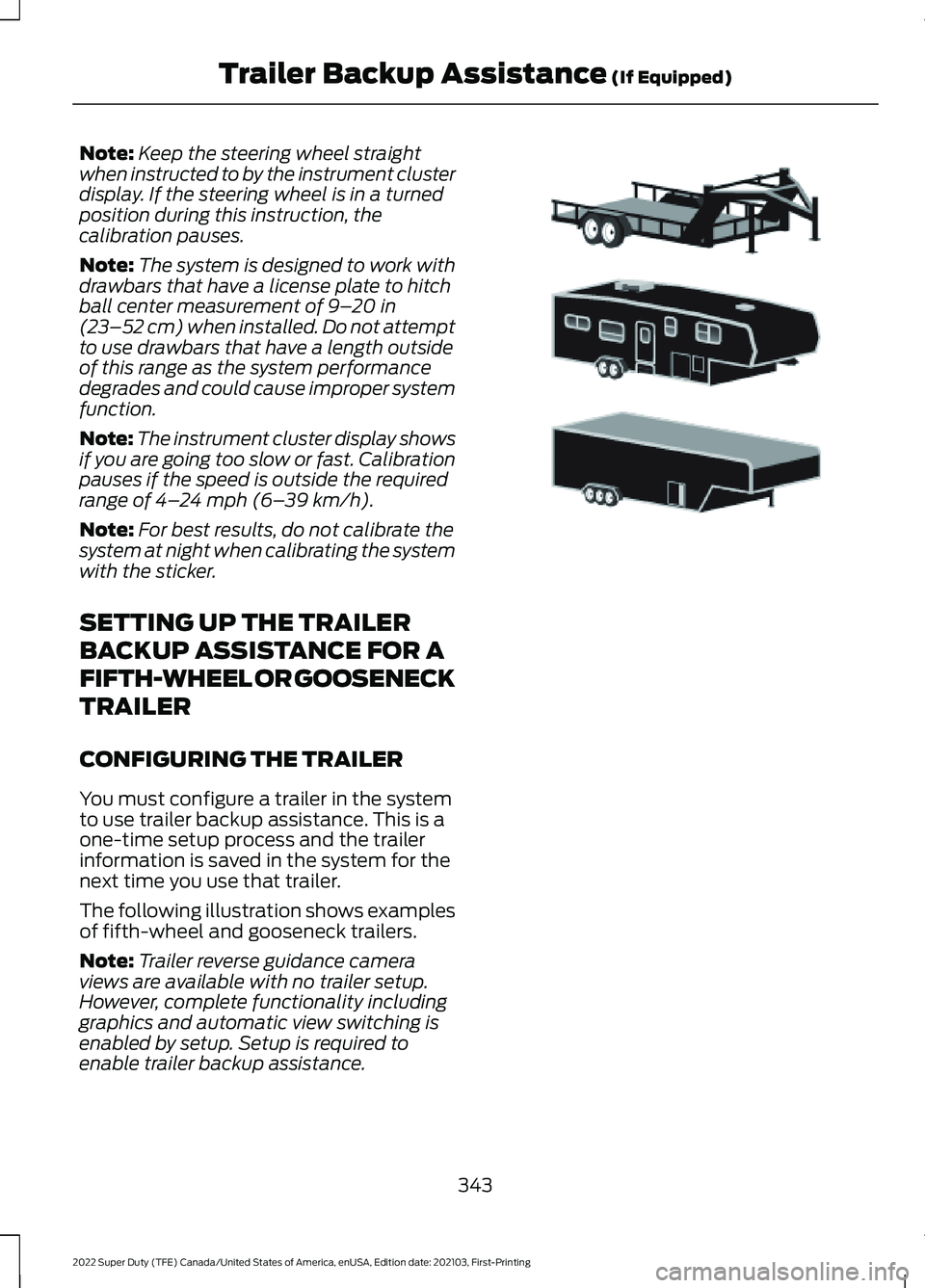
The following illustration shows examples
of fifth-wheel and gooseneck trailers.
Note: Trailer reverse guidance camera
views are available with no trailer setup.
However, complete functionality including
graphics and automatic view switching is
enabled by setup. Setup is required to
enable trailer backup assistance. 343
2022 Super Duty (TFE) Canada/United States of America, enUSA, Edition date: 202103, First-Printing Trailer Backup Assistance
(If Equipped)E311877