2022 CHRYSLER VOYAGER tow
[x] Cancel search: towPage 79 of 316

GETTING TO KNOW YOUR VEHICLE77
NOTE:Tones are sounded and the turn signals are
flashed with liftgate movements. These alerts can
be turned on or off in Uconnect Settings
Úpage 141.
To Close The Liftgate
The liftgate can also be closed using the Rear
Interior Power Liftgate button (if equipped), located
in the upper left trim in the liftgate opening.
Rear Interior Power Liftgate Switch
To Lock The Vehicle
With a valid Passive Entry key fob within 5 ft
(1.5 m) of the liftgate, pushing the Passive Entry
lock button located to the right of the outside
handle will lock the vehicle.
CARGO AREA FEATURES
Cargo Area Storage
When the third row seats are not in the stowed
position, there is a large area for cargo storage.
Rear Cargo Area
NOTE:With all rear seats stowed or removed, 4 x 8 ft
(1.2 x 2.4 m) sheets of building material will fit on
the vehicle floor with the liftgate closed. The front
seats must be moved slightly forward of the
rearmost position.
STOW ‘N PLACE ROOF RACK — IF EQUIPPED
The crossbars and side rails are designed to carry
weight on vehicles equipped with a luggage rack.
The load must not exceed 150 lb (68 kg), and
should be uniformly distributed over the luggage
rack crossbars.
The crossbars on your vehicle are delivered stowed
within the roof rack side rails. Crossbars should
always be used whenever cargo is placed on the
roof rack. Check the straps frequently to be sure
that the load remains securely attached.
Roof Rack
1 — Side Rail
2 — Crossbar
2
22_RUVG_OM_EN_USC_t.book Page 77
Page 80 of 316

78GETTING TO KNOW YOUR VEHICLE
The Stow ‘N Place roof rack does not increase the
total load carrying capacity of the vehicle. Be sure
the total load of cargo inside the vehicle plus that
on the external rack does not exceed the maximum
vehicle load capacity.
DEPLOYING THE CROSSBARS
1. To deploy the crossbars, completely loosen the thumb screws at both ends of the
crossbar and lift the crossbar from its stowed
position in the side rail. Repeat with crossbar
on the opposite side.
Thumb Screw
NOTE:The thumb screws cannot be fully removed.
Removing Crossbars
2. Bend the crossbar supports at each end,
taking care to keep hand clear of pivoting joint.
Slide the thumb screw down.
Bending Pivot
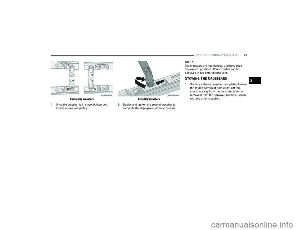
3. Position the crossbars across the roof making sure the letters on the crossbars align with the
matching letters on the side rail.
CAUTION!
Use care when removing and handling the
crossbars to prevent damage to the vehicle.
22_RUVG_OM_EN_USC_t.book Page 78
Page 81 of 316
GETTING TO KNOW YOUR VEHICLE79
Positioning Crossbars
4. Once the crossbar is in place, tighten both thumb screws completely.
Installing Crossbars
5. Deploy and tighten the second crossbar to complete the deployment of the crossbars.
NOTE:The crossbars are not identical and have fixed
deployment positions. Rear crossbar can be
deployed in two different positions.
STOWING THE CROSSBARS
1. Starting with one crossbar, completely loosen the thumb screws at both ends. Lift the
crossbar away from the matching letter to
remove it from the deployed position. Repeat
with the other crossbar.
2
22_RUVG_OM_EN_USC_t.book Page 79
Page 82 of 316

80GETTING TO KNOW YOUR VEHICLE
2. Starting with the one crossbar, bend up the pivot supports at each end.
Crossbar Pivot
3. Then, position the crossbar along the correct side rail. Make sure the letters on the crossbar
align with the matching letters on the side rail.
Stowing Crossbars
4. The crossbar will nest fully within the side rail.
Crossbar To Side Rail
5. Once the driver’s side crossbar is in place,
tighten the thumb screws completely.
Tightening Crossbar
6. Repeat the procedure to stow the second crossbar on the opposite side.
Stowed Crossbars
CAUTION!
Use care when removing and handling the
crossbars to prevent damage to the vehicle.
22_RUVG_OM_EN_USC_t.book Page 80
Page 83 of 316

GETTING TO KNOW YOUR VEHICLE81
(Continued)
NOTE:
To help control wind noise, stow the crossbars in
the side rails when they are not in use.
If any metallic object is placed over the satellite
radio antenna (if equipped), you may experience
interruption of satellite radio reception.
WARNING!
Cargo must be securely tied down before driving
your vehicle. Improperly secured loads can fly off
the vehicle, particularly at high speeds, resulting
in personal injury or property damage. Follow
the roof rack cautions when carrying cargo on
your roof rack.
CAUTION!
To prevent damage to the roof of your vehicle,
DO NOT carry any loads on the roof rack
without the crossbars deployed. The load
should be secured and placed on top of the
crossbars, not directly on the roof. If it is
necessary to place the load on the roof, place
a blanket or other protective layer between
the load and the roof surface.
To avoid damage to the roof rack and vehicle,
do not exceed the maximum roof rack load
capacity of 150 lb (68 kg). Always distribute
heavy loads as evenly as possible and secure
the load appropriately.
Load should always be secured to cross bars
first, with tie down loops used as additional
securing points if needed. Tie loops are
intended as supplementary tie down points
only. Do not use ratcheting mechanisms with
the tie loops. Check the straps and thumb
wheels frequently to be sure that the load
remains securely attached.
Long loads that extend over the windshield,
such as wood panels or surfboards, or loads
with large frontal area should be secured to
both the front and rear of the vehicle.
Travel at reduced speeds and turn corners
carefully when carrying large or heavy loads
on the roof rack. Wind forces, due to natural
causes or nearby truck traffic, can add sudden
upward lift to a load. This is especially true on
large flat loads and may result in damage to
the cargo or your vehicle.
CAUTION!
2
22_RUVG_OM_EN_USC_t.book Page 81
Page 96 of 316

94GETTING TO KNOW YOUR INSTRUMENT PANEL
Loss of the battery charge may indicate one or
more of the following conditions:
The charging system cannot deliver enough
electrical power to the vehicle system because
the electrical loads are larger than the capability
of charging system. The charging system is still
functioning properly.
Turning on all possible vehicle electrical loads
(e.g. HVAC to max settings, exterior and interior
lights, overloaded power outlets +12 Volts,
150W, USB ports) during certain driving condi -
tions (city driving, towing, frequent stopping).
Installing options like additional lights, upfitter
electrical accessories, audio systems, alarms
and similar devices.
Unusual driving cycles (short trips separated by
long parking periods).
The vehicle was parked for an extended period
of time (weeks, months).
The battery was recently replaced and was not
charged completely.
The battery was discharged by an electrical load
left on when the vehicle was parked.
The battery was used for an extended period
with the engine not running to supply radio,
lights, chargers, +12 Volt portable appliances
like vacuum cleaners, game consoles and
similar devices. What to do when an electrical load reduction
action message is present (“Battery Saver On” or
“Battery Saver Mode”)
During a trip:
Reduce power to unnecessary loads if possible:
Turn off redundant lights (interior or exte
-
rior)
Check what may be plugged in to power
outlets +12 Volts, 150W, USB ports
Check HVAC settings (blower, temperature)
Check the audio settings (volume)
After a trip:
Check if any aftermarket equipment was
installed (additional lights, upfitter electrical
accessories, audio systems, alarms) and review
specifications if any (load and Ignition Off Draw
currents).
Evaluate the latest driving cycles (distance,
driving time and parking time).
The vehicle should have service performed if
the message is still present during consecutive
trips and the evaluation of the vehicle and
driving pattern did not help to identify the cause.
TRIP COMPUTER
The Trip Computer is located in the instrument
cluster display. Push and release the up or
down arrow button until “Trip Info” is
highlighted in the instrument cluster display.
Navigate between Trip A or Trip B by using the
right and left arrow buttons.
For each trip the following information will be
displayed:
Trip A
Shows the total distance traveled for Trip A
since the last reset.
Shows the Average MPG for Trip A since the last
reset.
Shows the elapsed time traveled for Trip A since
the last reset. Elapsed time will increment when
the ignition switch is in the ON or START posi -
tion.
22_RUVG_OM_EN_USC_t.book Page 94
Page 98 of 316

96GETTING TO KNOW YOUR INSTRUMENT PANEL
Vehicles equipped with the Anti-Lock Brake System
(ABS) are also equipped with Electronic Brake
Force Distribution (EBD). In the event of an EBD
failure, the Brake Warning Light will turn on along
with the ABS Light. Immediate repair to the ABS
system is required.
Operation of the Brake Warning Light can be
checked by turning the ignition switch from the OFF
position to the ON/RUN position. The light should
illuminate for approximately two seconds. The light
should then turn off unless the parking brake is
applied or a brake fault is detected. If the light does
not illuminate, have the light inspected by an
authorized dealer.
The light also will turn on when the parking brake
is applied with the ignition switch in the ON/RUN
position.
NOTE:This light shows only that the parking brake is
applied. It does not show the degree of brake appli -
cation.
Door Open Warning Light — If Equipped
This warning light will illuminate when a
door is ajar/open and not fully closed.
This indicator will reflect which doors are
open.
NOTE:If the vehicle is moving, there will also be a single
chime.
Electric Power Steering (EPS) Fault
Warning Light
This warning light will turn on when
there's a fault with the EPS system
Úpage 116.
Electronic Throttle Control (ETC) Warning
Light
This warning light will illuminate to
indicate a problem with the ETC system.
If a problem is detected while the vehicle
is running, the light will either stay on or
flash depending on the nature of the problem.
Cycle the ignition when the vehicle is safely and
completely stopped and the transmission is placed
in the PARK (P) position. The light should turn off.
If the light remains on with the vehicle running,
your vehicle will usually be drivable; however, see
an authorized dealer for service as soon as
possible.
NOTE:This light may turn on if the accelerator and brake
pedals are pressed at the same time.
If the light continues to flash when the vehicle is
running, immediate service is required and you
may experience reduced performance, an
elevated/rough idle, or engine stall and your
vehicle may require towing. The light will come on
when the ignition is placed in the ON/RUN or ACC/
ON/RUN position and remain on briefly as a bulb
check. If the light does not come on during starting,
have the system checked by an authorized dealer.
WARNING!
Driving a vehicle with the red brake light on is
dangerous. Part of the brake system may have
failed. It will take longer to stop the vehicle. You
could have a collision. Have the vehicle checked
immediately.
WARNING!
Continued operation with reduced assist could
pose a safety risk to yourself and others. Service
should be obtained as soon as possible.
22_RUVG_OM_EN_USC_t.book Page 96
Page 99 of 316

GETTING TO KNOW YOUR INSTRUMENT PANEL97
Engine Coolant Temperature Warning
Light
This warning light warns of an
overheated engine condition. If the
engine coolant temperature is too high,
this indicator will illuminate and a single
chime will sound. If the temperature reaches the
upper limit, a continuous chime will sound for four
minutes or until the engine is able to cool;
whichever comes first.
If the light turns on while driving, safely pull over
and stop the vehicle. If the Air Conditioning (A/C)
system is on, turn it off. Also, shift the transmission
into NEUTRAL (N) and idle the vehicle. If the
temperature reading does not return to normal,
turn the engine off immediately and call for service
Úpage 237.
Hood Open Warning Light
This warning light will illuminate when the
hood is left open and not fully closed.
NOTE:If the vehicle is moving, there will also be a single
chime.
Liftgate Open Warning Light
This warning light will illuminate when the
liftgate is open.
NOTE:If the vehicle is moving, there will also be a single
chime.
Oil Temperature Warning Light
This warning light will illuminate to
indicate the engine oil temperature is
high. If the light turns on while driving,
stop the vehicle and shut off the engine
as soon as possible. Wait for oil temperature to
return to normal levels.
Oil Pressure Warning Light
This warning light will illuminate to
indicate low engine oil pressure. If the
light turns on while driving, stop the
vehicle, shut off the engine as soon as
possible, and contact an authorized dealer. A
chime will sound when this light turns on.
Do not operate the vehicle until the cause is
corrected. This light does not indicate how much oil
is in the engine. The engine oil level must be
checked under the hood.
Seat Belt Reminder Warning Light
This warning light indicates when the
driver or passenger seat belt is
unbuckled. When the ignition is first
placed in the ON/RUN or ACC/ON/RUN
position and if the driver’s seat belt is unbuckled,
a chime will sound and the light will turn on. When
driving, if the driver or front passenger seat belt
remains unbuckled, the Seat Belt Reminder Light
will flash or remain on continuously and a chime
will sound
Úpage 174.
Transmission Temperature Warning Light
— If Equipped
This warning light will illuminate to warn
of a high transmission fluid temperature.
This may occur with strenuous usage
such as trailer towing. If this light turns
on, stop the vehicle and run the engine at idle or
slightly faster, with the transmission in PARK (P) or
NEUTRAL (N), until the light turns off. Once the light
turns off, you may continue to drive normally.
WARNING!
If you continue operating the vehicle when the
Transmission Temperature Warning Light is
illuminated you could cause the fluid to boil over,
come in contact with hot engine or exhaust
components and cause a fire.
3
22_RUVG_OM_EN_USC_t.book Page 97