2022 CHRYSLER PACIFICA instrument panel
[x] Cancel search: instrument panelPage 81 of 384

GETTING TO KNOW YOUR VEHICLE79
Push the blue button on the faceplate or
touchscreen or press and slide the
temperature bar towards the blue arrow
button on the touchscreen for cooler
temperature settings.
SYNC Button
Press the SYNC button on the
touchscreen to toggle the Sync feature
on/off. The SYNC indicator is illuminated
when this feature is enabled. SYNC is
used to synchronize the front and rear passenger
temperature settings with the driver temperature
setting. Changing the front or rear passenger
temperature setting while in SYNC will
automatically exit this feature. Pressing SYNC on
the touchscreen while in the Front Climate screen
synchronizes the driver and passenger
temperatures only. In order to SYNC rear
temperature to driver temperature, the
touchscreen must be on the Rear Climate screen.
NOTE:The SYNC setting is only available on the touch -
screen.
Blower Control
Blower Control is used to regulate the
amount of air forced through the Climate
Control system. There are seven blower
speeds available. The speeds can be
selected using either the blower control knob on
the faceplate or the buttons on the touchscreen.
Faceplate: The blower speed increases as you
turn the blower control knob clockwise from the
lowest blower setting. The blower speed
decreases as you turn the blower control knob
counterclockwise.
Touchscreen: Use the small blower icon to
reduce the blower setting and the large blower
icon to increase the blower setting. Blower
speed can also be selected by pressing the
blower bar area between the icons.
Mode Control
The airflow distribution mode can be
adjusted so air comes from the
instrument panel outlets, floor outlets,
defrost outlets and demist outlets.
Faceplate: Push the button in the center of the
knob to change the airflow distribution mode.
Touchscreen: Select Mode by pressing one of the
Mode Buttons on the touchscreen.
Panel Mode
Air comes from the outlets in the
instrument panel. Each of these outlets
can be individually adjusted to direct the
flow of air. The air vanes of the center
outlets and outboard outlets can be moved up and
down or side to side to regulate airflow direction.
There is a shut-off wheel located below the air
vanes to shut off or adjust the amount of airflow
from these outlets.
Bi-Level Mode
Air comes from the instrument panel
outlets and floor outlets. A slight amount
of air is directed through the defrost and
side window demister outlets.
NOTE:Bi-Level mode is designed under comfort condi -
tions to provide cooler air out of the panel outlets
and warmer air from the floor outlets.
Floor Mode
Air comes from the floor outlets. A slight
amount of air is directed through the
defrost and side window demister
outlets.
2
22_RUP_OM_EN_USC_t.book Page 79
Page 86 of 384

84GETTING TO KNOW YOUR VEHICLE
INTERIOR STORAGE AND EQUIPMENT
STORAGE
Glove Compartment
The glove compartment is located on the
passenger side of the instrument panel.
To open the glove compartment, pull the release
handle.
Release Handle
Front Door Storage
Both interior front door panels have multiple
pockets for storage.
Overhead Sunglass Storage
At the front of the overhead console, a
compartment is provided for the storage of one
pair of sunglasses.
From the closed position, push the indentation to
open the compartment.
Overhead Sunglass Door Latch
The door will slowly rotate to the full open position.
Instrument Panel Drawer
There is a storage drawer located in the lower
center of the instrument panel. It can be released
by pushing the access button above it. The drawer
is actuator assisted once the access button is
pushed. Pull drawer outward to the fully open
position.
Drawer Access Button
WARNING!
If containers of hot liquid are placed in the bottle
holder, they can spill when the door is closed,
burning the occupants. Be careful when closing
the doors to avoid injury.
CAUTION!
The storage drawer must be closed while driving.
If left open during a collision, additional damage
may occur to property or the drawer mechanism.
22_RUP_OM_EN_USC_t.book Page 84
Page 90 of 384

88GETTING TO KNOW YOUR VEHICLE
There are multiple USB “Charge Only” ports in this
vehicle.
In the center console
On the instrument panel
On the back of the front row seats in the Ucon -
nect Theater Media Hubs (if equipped)
On the back of the front row seats
Above the rear cup holder in the third row of
seats
Charge Only USB In The Center Console
NOTE:The USB outlet in the bottom of the instrument
panel can be switched from ignition only to
constant battery powered all the time. See an
authorized dealer for details.
Rear Seat USB Charging Port Without Uconnect Theater
Rear Seat USB Media Hub With Uconnect Theater 3rd Row USB Charging Port
NOTE:The USB “Charge Only” ports will recharge battery
operated USB devices when connected.
Different scenarios are listed below when a
non-phone device is plugged into the smaller and
larger USB ports, and when a phone device is
plugged into the smaller and larger USB ports:
“A new device is now connected. Previous
connection was lost”.
“(Phone Name) now connected. Previous
connection was lost”.
“Another device is in use through the same USB
port. Please disconnect the first device to use
the second device”.1 — Headphone Jack (Headphone Output Only)
2 — HDMI Port
3 — USB Port (Charge Only)
22_RUP_OM_EN_USC_t.book Page 88
Page 91 of 384

GETTING TO KNOW YOUR VEHICLE89
Plugging in a phone or another USB device may
cause the connection to a previous device to be
lost.
NOTE:Charge unsupported devices with the Charge Only
USB ports. If an unsupported device is plugged into
a Media USB port, a message will display on the
touchscreen that the device is not supported by
the system.
POWER OUTLETS
Your vehicle is equipped with 12 Volt (15 Amp)
power outlets, and 5 Volt (2.5 Amp) USB ports, that
can be used to power cellular phones, small
electronics and other low powered electrical
accessories. The power outlets can be labeled with
either a “key” or a “battery” symbol to indicate how
the outlet is powered. Power outlets labeled with a
key symbol are powered when the ignition is in the
ACC or ON/RUN position, while the outlets labeled
with a battery symbol are connected directly to the
battery and powered at all times.
NOTE:All accessories connected to the battery powered
outlets should be removed or turned off when the
vehicle is not in use to protect the battery against
discharge. Depending on the type of center console your
vehicle is equipped with, there is a front power
outlet located either on the center stack, bottom of
the instrument panel, or inside the center console.
12 Volt Front Power Outlet (On Center Stack) - If Equipped
12 Volt Front Power Outlet (In Floor Tray) - If Equipped
12 Volt Front Power Outlet (In Center Console)
CAUTION!
Power outlets are designed for accessory plugs
only. Do not insert any other object in the power
outlets as this will damage the outlet and blow
the fuse. Improper use of the power outlet can
cause damage not covered by your New Vehicle
Limited Warranty.
2
22_RUP_OM_EN_USC_t.book Page 89
Page 92 of 384

90GETTING TO KNOW YOUR VEHICLE
(Continued)
In addition to the front power outlet, there is also a
power outlet located in the rear cargo area.
The rear power outlet is located in the right rear
cargo area.
Rear Power Outlet
NOTE:The instrument panel power outlet can be changed
to battery powered at all times by switching the
power outlet fuse in the Power Distribution Center
panel from fuse location F95A to F95B.
Power Outlet Fuse Locations
1 — F95A (Ignition)/F95B (Battery)
Front Power Outlet 10A
2 — F85 Cigar Lighter 20A
3 — F60 RR Cargo Power Outlet 20A
WARNING!
To avoid serious injury or death:
Only devices designed for use in this type of
outlet should be inserted into any 12 Volt
outlet.
Do not touch with wet hands.
Close the lid when not in use and while driving
the vehicle.
If this outlet is mishandled, it may cause an
electric shock and failure.
CAUTION!
Many accessories that can be plugged in draw
power from the vehicle's battery, even when
not in use (i.e., cellular phones, etc.). Eventu
-
ally, if plugged in long enough, the vehicle's
battery will discharge sufficiently to degrade
battery life and/or prevent the engine from
starting.
Accessories that draw higher power (i.e.,
coolers, vacuum cleaners, lights, etc.) will
degrade the battery even more quickly. Only use
these intermittently and with greater caution.
After the use of high power draw accessories,
or long periods of the vehicle not being started
(with accessories still plugged in), the vehicle
must be driven a sufficient length of time to
allow the generator to recharge the vehicle's
battery.
WARNING!
22_RUP_OM_EN_USC_t.book Page 90
Page 98 of 384

96GETTING TO KNOW YOUR VEHICLE
IGNITION OFF OPERATION
The power sunroof switch will remain active for up
to approximately 10 minutes after the ignition
switch is placed in the OFF position. Opening either
front door will cancel this feature.
NOTE:Ignition off time is programmable through the
Uconnect system Úpage 188.
SUNROOF MAINTENANCE
Use only a non-abrasive cleaner and a soft cloth to
clean the glass panel. Periodically check for and
clear out any debris that may have collected in the
tracks.
HOOD
OPENING
If applicable, refer to the “Hybrid Supplement” for
additional information.
The hood release lever (to open the primary latch)
and safety latch (to open the secondary latch)
must be released to open the hood.
1. Pull the hood release lever located under the
driver’s side of the instrument panel.
Hood Release Lever
2. Move to the outside of the front of the vehicle.
3. Push the safety latch release lever toward the passenger side of the vehicle. The safety latch
is located behind the center front edge of the
hood.
Safety Latch Release Lever Location
4. Remove the support rod from the locking tab
and insert it into the seat located on the
underside of the hood.
NOTE:
Before lifting the hood, check that the wiper arms
are not in motion and not in the lifted position.
While lifting the hood, use both hands.
Vehicle must be at a stop and the gear selector
must be in PARK.
CLOSING
If applicable, refer to the “Hybrid Supplement” for
additional information.
1. Hold up the hood with one hand and with the other hand remove the support rod from its
seat and reinsert it into the locking tab.
2. Lower the hood to approximately 12 inches (30 cm) from the engine compartment and
drop it. Make sure that the hood is completely
closed.
WARNING!
Be sure the hood is fully latched before driving
your vehicle. If the hood is not fully latched, it
could open when the vehicle is in motion and
block your vision. Failure to follow this warning
could result in serious injury or death.
22_RUP_OM_EN_USC_t.book Page 96
Page 112 of 384

110
GETTING TO KNOW YOUR INSTRUMENT PANEL
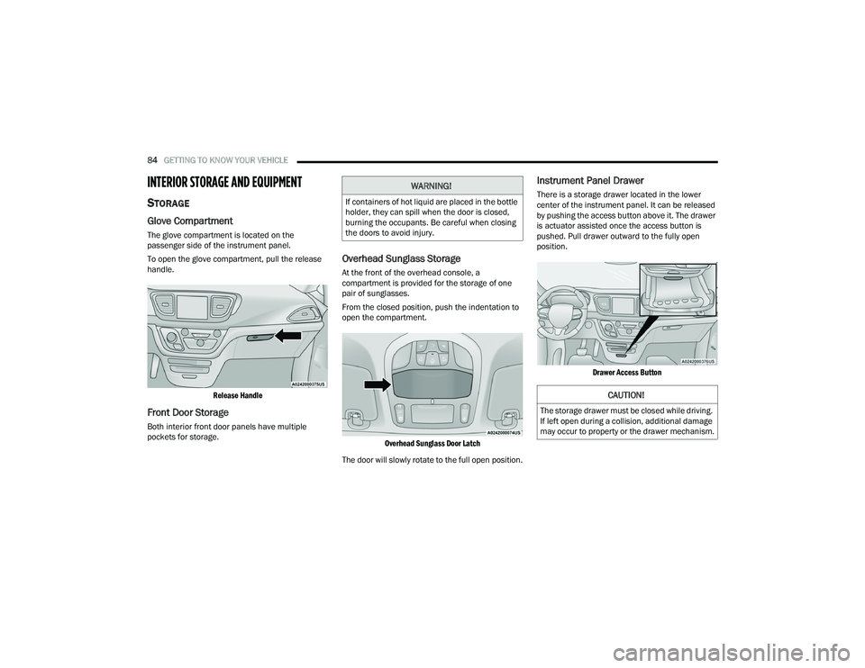
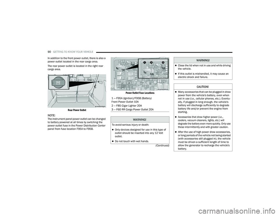
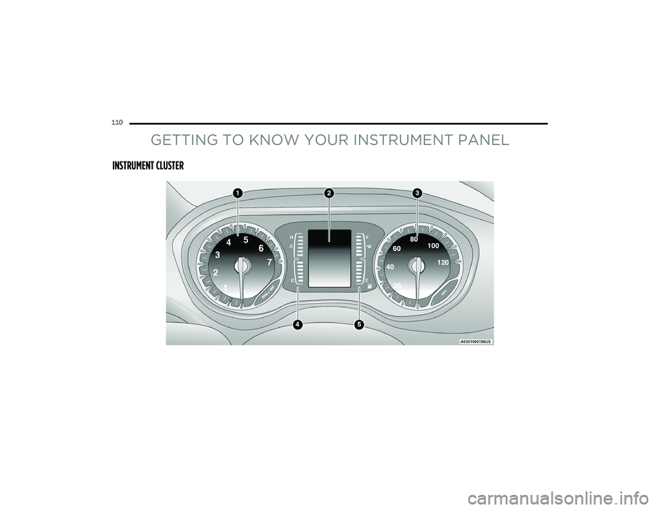
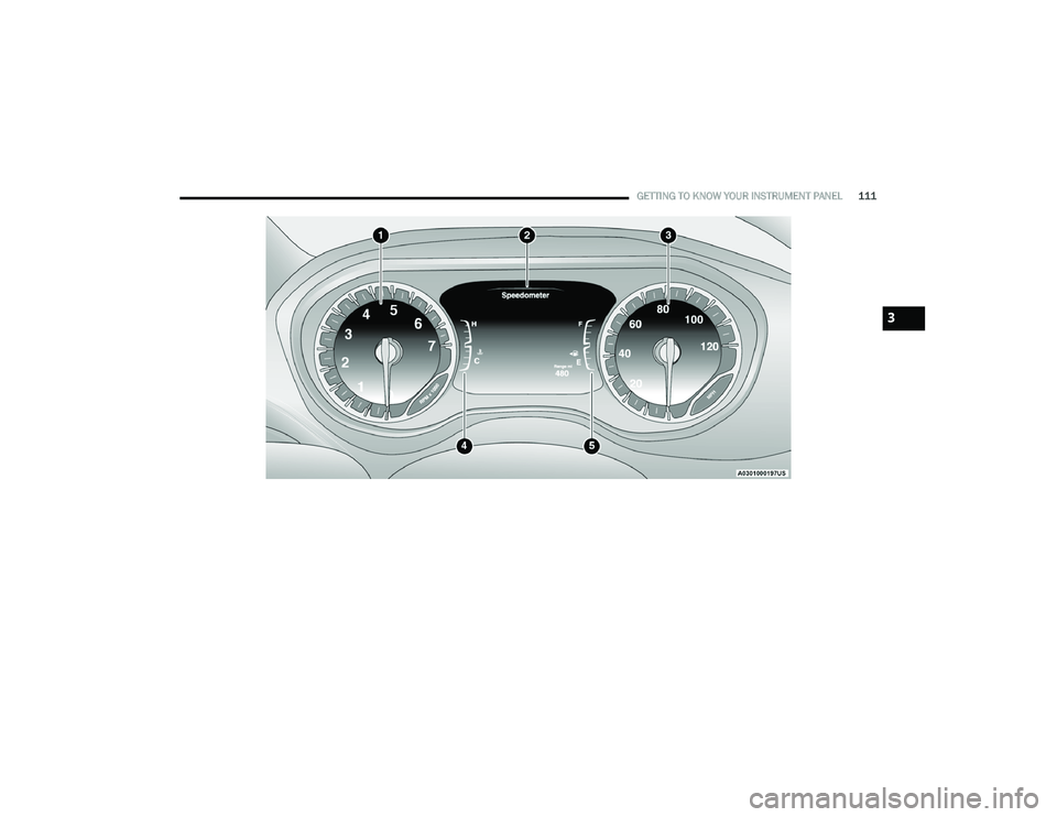
INSTRUMENT CLUSTER
22_RUP_OM_EN_USC_t.book Page 110
Page 113 of 384

GETTING TO KNOW YOUR INSTRUMENT PANEL111
3
22_RUP_OM_EN_USC_t.book Page 111