2022 CHRYSLER PACIFICA accessory
[x] Cancel search: accessoryPage 9 of 384

7
JUMP STARTING................................................... 300 Preparations For Jump Start......................... 301Jump Starting Procedure .............................. 301
REFUELING IN EMERGENCY –
IF EQUIPPED ......................................................... 302
IF YOUR ENGINE OVERHEATS ............................ 303
MANUAL PARK RELEASE .................................. 304
FREEING A STUCK VEHICLE .............................. 305
TOWING A DISABLED VEHICLE .......................... 306
All Wheel Drive (AWD) Models ...................... 308
ENHANCED ACCIDENT RESPONSE SYSTEM
(EARS) .................................................................. 308
EVENT DATA RECORDER (EDR) ......................... 308
SERVICING AND MAINTENANCE
SCHEDULED SERVICING ..................................... 309
Maintenance Plan ......................................... 310
ENGINE COMPARTMENT .................................... 313
3.6L Engine.................................................... 313
Checking Oil Level ......................................... 314
Adding Washer Fluid .................................... 314
Maintenance-Free Battery ........................... 314
Pressure Washing ......................................... 315 VEHICLE MAINTENANCE..................................... 315
Engine Oil ...................................................... 315
Engine Oil Filter ............................................. 316Engine Air Cleaner Filter ............................... 316
Accessory Drive Belt Inspection ................... 317Air Conditioner Maintenance........................ 317
Body Lubrication ........................................... 320Windshield Wiper Blades.............................. 320Exhaust System ............................................ 323
Cooling System .............................................. 324
Brake System ............................................... 327
Automatic Transmission .............................. 328Fuses.............................................................. 329
Bulb Replacement......................................... 337
TIRES ................................................................... 339
Tire Safety Information ................................. 339
Tires — General Information ......................... 346
Tire Types....................................................... 350
Spare Tires — If Equipped ............................ 350
Wheel And Wheel Trim Care ........................ 352
Snow Traction Devices ................................. 353
Tire Rotation Recommendations ................. 355 DEPARTMENT OF TRANSPORTATION
UNIFORM TIRE QUALITY GRADES .................... 355
Treadwear...................................................... 356
Traction Grades ............................................. 356Temperature Grades..................................... 356
STORING THE VEHICLE ....................................... 357
BODYWORK .......................................................... 357
Protection From Atmospheric Agents ......... 357
Body And Underbody Maintenance ............. 357
Preserving The Bodywork ............................. 357
INTERIORS ........................................................... 358
Seats And Fabric Parts ................................. 358
Plastic And Coated Parts .............................. 359
Leather Surfaces........................................... 359
Glass Surfaces ............................................. 359TECHNICAL SPECIFICATIONS
VEHICLE IDENTIFICATION NUMBER
(VIN) ....................................................................... 360
BRAKE SYSTEM ................................................... 360
WHEEL AND TIRE TORQUE
SPECIFICATIONS .................................................. 360Torque Specifications ................................... 360
22_RUP_OM_EN_USC_t.book Page 7
Page 91 of 384

GETTING TO KNOW YOUR VEHICLE89
Plugging in a phone or another USB device may
cause the connection to a previous device to be
lost.
NOTE:Charge unsupported devices with the Charge Only
USB ports. If an unsupported device is plugged into
a Media USB port, a message will display on the
touchscreen that the device is not supported by
the system.
POWER OUTLETS
Your vehicle is equipped with 12 Volt (15 Amp)
power outlets, and 5 Volt (2.5 Amp) USB ports, that
can be used to power cellular phones, small
electronics and other low powered electrical
accessories. The power outlets can be labeled with
either a “key” or a “battery” symbol to indicate how
the outlet is powered. Power outlets labeled with a
key symbol are powered when the ignition is in the
ACC or ON/RUN position, while the outlets labeled
with a battery symbol are connected directly to the
battery and powered at all times.
NOTE:All accessories connected to the battery powered
outlets should be removed or turned off when the
vehicle is not in use to protect the battery against
discharge. Depending on the type of center console your
vehicle is equipped with, there is a front power
outlet located either on the center stack, bottom of
the instrument panel, or inside the center console.
12 Volt Front Power Outlet (On Center Stack) - If Equipped
12 Volt Front Power Outlet (In Floor Tray) - If Equipped
12 Volt Front Power Outlet (In Center Console)
CAUTION!
Power outlets are designed for accessory plugs
only. Do not insert any other object in the power
outlets as this will damage the outlet and blow
the fuse. Improper use of the power outlet can
cause damage not covered by your New Vehicle
Limited Warranty.
2
22_RUP_OM_EN_USC_t.book Page 89
Page 94 of 384

92GETTING TO KNOW YOUR VEHICLE
The wireless charging pad is equipped with an
anti-slip mat to hold your mobile phone in place,
and an LED indicator light.
LED Indicator Status:
No Light: Charging pad is idle or searching for a
device.
Blue Light: Device is detected and is charging.
Red Light/Flashing: Internal error or foreign
object is detected.
NOTE:
All vehicle doors must be closed for the wireless
charging pad to operate.
Using a phone case may interfere with wireless
charging.
WINDOWS
POWER WINDOWS
The window switches on the driver’s door trim
panel control all of the door windows.
Driver’s Power Window Controls
The driver may lock out the rear power windows by
pushing the bar control just below the power
window controls.
Window Lockout Switch
The window switches will operate only when the
ignition is in the ACC or ON/RUN position and
during power accessory delay.
NOTE:Power Window controls will also remain active for
up to 10 minutes after the ignition has been
placed in the OFF position, depending upon the
accessory delay setting. Opening a front door will
cancel this feature.
There is a single control on the front passenger’s
door trim panel which operates the passenger door
window and a set of controls that lock and unlock
all doors. The controls will operate only when the
ignition is in the ACC or ON/RUN position and
during power accessory delay.CAUTION!
The key fob should not be placed on the
charging pad or within 6 inches (15 cm) of it.
Doing so can cause excessive heat buildup and
damage to the fob. Placing the fob in close
proximity of the charging pad blocks the fob from
being detected by the vehicle and prevents the
vehicle from starting.
22_RUP_OM_EN_USC_t.book Page 92
Page 95 of 384

GETTING TO KNOW YOUR VEHICLE93
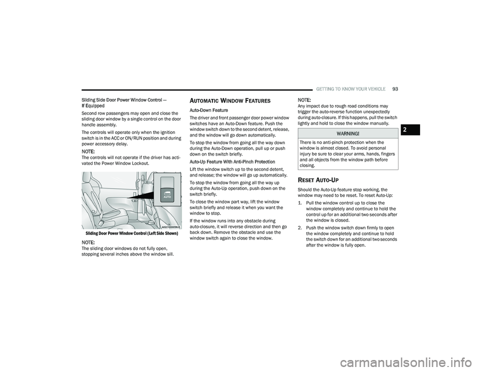
Sliding Side Door Power Window Control —
If Equipped
Second row passengers may open and close the
sliding door window by a single control on the door
handle assembly.
The controls will operate only when the ignition
switch is in the ACC or ON/RUN position and during
power accessory delay.
NOTE:The controls will not operate if the driver has acti-
vated the Power Window Lockout.
Sliding Door Power Window Control (Left Side Shown)
NOTE:The sliding door windows do not fully open,
stopping several inches above the window sill.
AUTOMATIC WINDOW FEATURES
Auto-Down Feature
The driver and front passenger door power window
switches have an Auto-Down feature. Push the
window switch down to the second detent, release,
and the window will go down automatically.
To stop the window from going all the way down
during the Auto-Down operation, pull up or push
down on the switch briefly.
Auto-Up Feature With Anti-Pinch Protection
Lift the window switch up to the second detent,
and release; the window will go up automatically.
To stop the window from going all the way up
during the Auto-Up operation, push down on the
switch briefly.
To close the window part way, lift the window
switch briefly and release it when you want the
window to stop.
If the window runs into any obstacle during
auto-closure, it will reverse direction and then go
back down. Remove the obstacle and use the
window switch again to close the window.
NOTE:Any impact due to rough road conditions may
trigger the auto-reverse function unexpectedly
during auto-closure. If this happens, pull the switch
lightly and hold to close the window manually.
RESET AUTO-UP
Should the Auto-Up feature stop working, the
window may need to be reset. To reset Auto-Up:
1. Pull the window control up to close the window completely and continue to hold the
control up for an additional two seconds after
the window is closed.
2. Push the window switch down firmly to open the window completely and continue to hold
the switch down for an additional two seconds
after the window is fully open.
WARNING!
There is no anti-pinch protection when the
window is almost closed. To avoid personal
injury be sure to clear your arms, hands, fingers
and all objects from the window path before
closing.
2
22_RUP_OM_EN_USC_t.book Page 93
Page 104 of 384

102GETTING TO KNOW YOUR VEHICLE
The vacuum will operate in two modes:
Ignition in the ACC position: Engine remains off,
and vacuum usage is limited to 10 minutes.
Ignition in the START position: Engine is running,
and vacuum usage is unlimited until the
vehicle’s battery level falls below 60%.
NOTE:The vacuum will not operate when the ignition is in
the OFF position, or in the ON/RUN position with
the engine off. For more information on ignition
positions, see Ú page 18.
1. Before Using Vacuum:
Accessory (ACC) Mode Operation - For up to
10 minutes of operation
Always apply the parking brake, shift the trans -
mission into PARK, and push ignition button to
place ignition in Accessory (ACC) mode. The
engine will not be running in this mode. Do not
leave the key fob in or near the vehicle, or in a
location accessible to children.
NOTE:The vacuum system will run for 10 minutes off
battery power and then the vacuum will shut down.
A low battery indication light (LOW PWR) located
below the vacuum nozzle storage location will
come on one minute before the vacuum shuts
down. Engine Running (START) Operation - For more
than 10 minutes of operation
Position vehicle outdoors and fully open all
side windows.
Always apply the parking brake, shift the
transmission into PARK, and leave engine
running.
2. Unclip the vacuum nozzle and pull to extend
vacuum hose from the storage location.
NOTE:The hose can reach every corner of the vehicle
floor.
3. Install desired attachment if needed.
Front Storage Compartments
WARNING!
Carbon monoxide (CO) in exhaust gases can
cause serious injury or death. Follow these
precautions to prevent carbon monoxide
poisoning:
Do not inhale exhaust gases.
Do not start or run an engine in a closed
garage or confined area. Always position
vehicle outdoors and fully open all side
windows before using vacuum system with the
engine running.
Guard against carbon monoxide with proper
maintenance. Have the exhaust system
inspected every time the vehicle is raised.
Have any abnormal conditions repaired
promptly.
1 — Vacuum Nozzle Storage Location
2 — Attachment Compartment
22_RUP_OM_EN_USC_t.book Page 102
Page 259 of 384

SAFETY257
Supplemental Driver And Front Passenger
Knee Air Bags
This vehicle is equipped with a Supplemental
Driver Knee Air Bag mounted in the instrument
panel below the steering column and a
Supplemental Passenger Knee Air Bag mounted in
the instrument panel below the glove
compartment. The Supplemental Knee Air Bags
provide enhanced protection during a frontal
impact by working together with the seat belts,
pretensioners, and front air bags.
Supplemental Side Air Bags
Supplemental Seat-Mounted Side Air Bags (SABs)
This vehicle is equipped with Supplemental
Seat-Mounted Side Air Bags (SABs).
Supplemental Seat-Mounted Side Air Bags (SABs)
are located in the outboard side of the front seats.
The SABs are marked with “SRS AIRBAG” or
“AIRBAG” on a label or on the seat trim on the
outboard side of the seats.
The SABs may help to reduce the risk of occupant
injury during certain side impacts, in addition to
the injury reduction potential provided by the seat
belts and body structure.
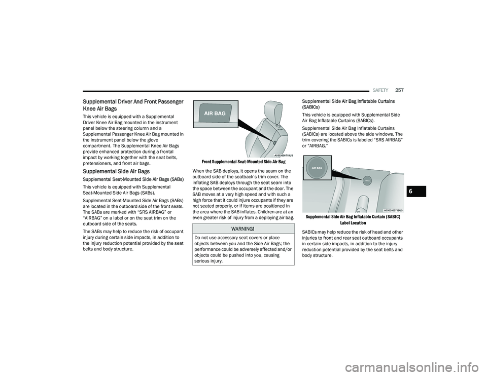
Front Supplemental Seat-Mounted Side Air Bag
When the SAB deploys, it opens the seam on the
outboard side of the seatback’s trim cover. The
inflating SAB deploys through the seat seam into
the space between the occupant and the door. The
SAB moves at a very high speed and with such a
high force that it could injure occupants if they are
not seated properly, or if items are positioned in
the area where the SAB inflates. Children are at an
even greater risk of injury from a deploying air bag. Supplemental Side Air Bag Inflatable Curtains
(SABICs)
This vehicle is equipped with Supplemental Side
Air Bag Inflatable Curtains (SABICs).
Supplemental Side Air Bag Inflatable Curtains
(SABICs) are located above the side windows. The
trim covering the SABICs is labeled “SRS AIRBAG”
or “AIRBAG.”
Supplemental Side Air Bag Inflatable Curtain (SABIC) Label Location
SABICs may help reduce the risk of head and other
injuries to front and rear seat outboard occupants
in certain side impacts, in addition to the injury
reduction potential provided by the seat belts and
body structure.
WARNING!
Do not use accessory seat covers or place
objects between you and the Side Air Bags; the
performance could be adversely affected and/or
objects could be pushed into you, causing
serious injury.
6
22_RUP_OM_EN_USC_t.book Page 257
Page 260 of 384

258SAFETY
The SABIC deploys downward, covering the side
windows. An inflating SABIC pushes the outside
edge of the headliner out of the way and covers the
window. The SABICs inflate with enough force to
injure occupants if they are not belted and seated
properly, or if items are positioned in the area
where the SABICs inflate. Children are at an even
greater risk of injury from a deploying air bag.
The SABICs may help reduce the risk of partial or
complete ejection of vehicle occupants through
side windows in certain side impact events. Side Impacts
The Side Air Bags are designed to activate in
certain side impacts. The Occupant Restraint
Controller (ORC) determines whether the
deployment of the Side Air Bags in a particular
impact event is appropriate, based on the severity
and type of collision. The side impact sensors aid
the ORC in determining the appropriate response
to impact events. The system is calibrated to
deploy the Side Air Bags on the impact side of the
vehicle during impacts that require Side Air Bag
occupant protection. In side impacts, the Side Air
Bags deploy independently; a left side impact
deploys the left Side Air Bags only and a right-side
impact deploys the right Side Air Bags only. Vehicle
damage by itself is not a good indicator of whether
or not Side Air Bags should have deployed.
The Side Air Bags will not deploy in all side
collisions, including some collisions at certain
angles, or some side collisions that do not impact
the area of the passenger compartment. The Side
Air Bags may deploy during angled or offset frontal
collisions where the front air bags deploy.
Side Air Bags are a supplement to the seat belt
restraint system. Side Air Bags deploy in less time
than it takes to blink your eyes.
WARNING!
Do not mount equipment, or stack luggage or
other cargo up high enough to block the
deployment of the SABICs. The trim covering
above the side windows where the SABIC and
its deployment path are located should
remain free from any obstructions.
In order for the SABICs to work as intended, do
not install any accessory items in your vehicle
which could alter the roof. Do not add an after
-
market sunroof to your vehicle. Do not add
roof racks that require permanent attach -
ments (bolts or screws) for installation on the
vehicle roof. Do not drill into the roof of the
vehicle for any reason.
WARNING!
Occupants, including children, who are up
against or very close to Side Air Bags can be
seriously injured or killed. Occupants,
including children, should never lean on or
sleep against the door, side windows, or area
where the side air bags inflate, even if they are
in an infant or child restraint.
Seat belts (and child restraints where appro -
priate) are necessary for your protection in all
collisions. They also help keep you in position,
away from an inflating Side Air Bag. To get the
best protection from the Side Air Bags, occu -
pants must wear their seat belts properly and
sit upright with their backs against the seats.
Children must be properly restrained in a child
restraint or booster seat that is appropriate for
the size of the child.
22_RUP_OM_EN_USC_t.book Page 258
Page 298 of 384

296IN CASE OF EMERGENCY
(Continued)
Tire Service Kit Usage Precautions
Replace the Tire Service Kit Sealant Bottle prior
to the expiration date (printed at the lower right
hand corner on the bottle label) to assure
optimum operation of the system. See the
Sealant Bottle Replacement in this section for
further information.
The Sealant Bottle is a one tire application use
and needs to be replaced after each use. Always
replace these components immediately at your
original equipment vehicle dealer.
When the Tire Service Kit sealant is in a liquid
form, clean water, and a damp cloth will remove
the material from the vehicle or tire and wheel
components. Once the sealant dries, it can
easily be peeled off and properly discarded.
For optimum performance, make sure the valve
stem on the wheel is free of debris before
connecting the Tire Service Kit.
The Tire Service Kit Sealant is only intended to
seal punctures less than 1/4 inch (6 mm) diam
-
eter in the tread/contact surface of your
vehicle’s tires.
The Tire Service Kit Sealant is not intended to
seal punctures on the tires' side walls.
You can use the Tire Service Kit air pump to
inflate bicycle tires. The kit also comes with two
needles, located in the Accessory Storage
Compartment (on the bottom of the air pump) for inflating sport balls, rafts, or similar inflat
-
able items. However, use only the Air Pump and
make sure the Mode Select Knob is in the Air
Mode when inflating such items to avoid
injecting sealant into them.
Do not lift or carry the Tire Service Kit by the
hoses.
WARNING!
Do not attempt to seal a tire on the side of the
vehicle closest to traffic. Pull far enough off
the road to avoid the danger of being hit when
using the Tire Service Kit.
Do not use Tire Service Kit or drive the vehicle
under the following circumstances:
If the puncture in the tire tread is approxi -
mately 1/4 inch (6 mm) or larger.
If the tire has any sidewall damage.
If the tire has any damage from driving
with extremely low tire pressure.
If the tire has any damage from driving on
a flat tire.
If the wheel has any damage.
If you are unsure of the condition of the
tire or the wheel.
Keep Tire Service Kit away from open flames
or heat source.
A loose Tire Service Kit thrown forward in a
collision or hard stop could endanger the
occupants of the vehicle. Always stow the Tire
Service Kit in the place provided. Failure to
follow these warnings can result in injuries
that are serious or fatal to you, your passen -
gers, and others around you.
Take care not to allow the contents of Tire
Service Kit to come in contact with hair, eyes,
or clothing. Tire Service Kit sealant is harmful
if inhaled, swallowed, or absorbed through the
skin. It causes skin, eye, and respiratory irrita -
tion. Flush immediately with plenty of water if
there is any contact with eyes or skin. Change
clothing as soon as possible, if there is any
contact with clothing.
Tire Service Kit Sealant solution contains
latex. In case of an allergic reaction or rash,
consult a physician immediately. Keep Tire
Service Kit out of reach of children. If swal -
lowed, rinse mouth immediately with plenty of
water and drink plenty of water. Do not induce
vomiting! Consult a physician immediately.
WARNING!
22_RUP_OM_EN_USC_t.book Page 296