2022 CHRYSLER PACIFICA AXLE
[x] Cancel search: AXLEPage 227 of 384

SAFETY225
Dynamic Steering Torque (DST)
DST is a feature of the ESC and Electric Power
Steering (EPS) modules that provides torque at the
steering wheel for certain driving conditions in
which the ESC module is detecting vehicle
instability. The torque that the steering wheel
receives is only meant to help the driver
realize optimal steering behavior in order to
reach/maintain vehicle stability. The only
notification the driver receives that the feature is
active, is the torque applied to the steering wheel.
NOTE:The DST feature is only meant to help the driver
realize the correct course of action through small
torques on the steering wheel, which means the
effectiveness of the DST feature is highly
dependent on the driver’s sensitivity and overall
reaction to the applied torque. It is very important
to realize that this feature will not steer the vehicle,
meaning the driver is still responsible for steering
the vehicle.
Electronic Brake Force Distribution (EBD)
The EBD function manages the distribution of the
braking torque between the front and rear axles by
limiting braking pressure to the rear axle. This is
done to prevent overslip of the rear wheels to avoid
vehicle instability, and to prevent the rear axle from
entering the Anti-Lock Brake System (ABS) before
the front axle.
Electronic Roll Mitigation (ERM)
ERM anticipates the potential for wheel lift by
monitoring the driver’s steering wheel input and
the speed of the vehicle. When ERM determines
that the rate of change of the steering wheel angle
and vehicle’s speed are sufficient to potentially
cause wheel lift, it then applies the appropriate
brake and may also reduce engine power to lessen
the chance that wheel lift will occur. ERM can only
reduce the chance of wheel lift occurring during
severe or evasive driving maneuvers; it cannot
prevent wheel lift due to other factors, such as
road conditions, leaving the roadway, striking
objects or other vehicles.
Electronic Stability Control (ESC)
ESC enhances directional control and stability of
the vehicle under various driving conditions. ESC
corrects for oversteering or understeering of the
vehicle by applying the brake of the appropriate
wheel(s) to assist in counteracting the above
conditions. Engine power may also be reduced to
help the vehicle maintain the desired path.
Oversteer — when the vehicle is turning more
than appropriate for the steering wheel position.
Understeer — when the vehicle is turning less
than appropriate for the steering wheel position.
ESC uses sensors in the vehicle to determine the
vehicle path intended by the driver and compares
it to the actual path of the vehicle. When the actual
path does not match the intended path, ESC
applies the brake of the appropriate wheel to
assist in counteracting the oversteer or understeer
condition.
WARNING!
Many factors, such as vehicle loading, road
conditions and driving conditions, influence the
chance that wheel lift or rollover may occur. ERM
cannot prevent all wheel lift or rollovers,
especially those that involve leaving the roadway
or striking objects or other vehicles. The
capabilities of an ERM-equipped vehicle must
never be exploited in a reckless or dangerous
manner which could jeopardize the user's safety
or the safety of others.
6
22_RUP_OM_EN_USC_t.book Page 225
Page 230 of 384

228SAFETY
Disabling And Enabling HSA
This feature can be turned on or turned off. To
change the current setting, proceed as follows:
Úpage 188.
Towing With HSA
HSA will also provide assistance to mitigate roll
back while towing a trailer.
Rain Brake Support (RBS)
RBS may improve braking performance in wet
conditions. It will periodically apply a small amount
of brake pressure to remove any water buildup on
the front brake rotors. It functions when the
windshield wipers are in LO or HI speed. When RBS
is active, there is no notification to the driver and
no driver interaction is required.
Ready Alert Braking (RAB)
RAB may reduce the time required to reach full
braking during emergency braking situations. It
anticipates when an emergency braking situation
may occur by monitoring how fast the throttle is
released by the driver. The Electronic Brake
Control (EBC) system will prepare the brake system
for a panic stop.
Rear Seat Reminder Alert (RSRA)
RSRA will consider the presence of an object in the
rear seat when a rear entry/exit door is opened at
the beginning of each key cycle. To activate, the
rear door must be open for more than one second
and the vehicle must be placed in the ON/RUN
position within 10 minutes. When the potential
presence of an object is determined and/or
otherwise inferred, a message will appear in the
instrument cluster display reminding driver to
check the rear seat(s) immediately after key off
accompanied by an alert upon exiting the vehicle.
Traction Control System (TCS)
The TCS monitors the amount of wheel spin of
each of the driven wheels. If wheel spin is
detected, the TCS may apply brake pressure to the
spinning wheel(s) and/or reduce vehicle power to
provide enhanced acceleration and stability. A
feature of the TCS, Brake Limited Differential (BLD)
functions similarly to a limited slip differential and
controls the wheel spin across a driven axle.
WARNING!
There may be situations where the Hill Start
Assist (HSA) will not activate and slight rolling
may occur, such as on minor hills or with a
loaded vehicle, or while pulling a trailer. HSA is
not a substitute for active driving involvement. It
is always the driver’s responsibility to be
attentive to distance to other vehicles, people,
and objects, and most importantly brake
operation to ensure safe operation of the vehicle
under all road conditions. Your complete
attention is always required while driving to
maintain safe control of your vehicle. Failure to
follow these warnings can result in a collision or
serious personal injury.
WARNING!
If you use a trailer brake controller with your
trailer, the trailer brakes may be activated and
deactivated with the brake switch. If so, there
may not be enough brake pressure to hold
both the vehicle and the trailer on a hill when
the brake pedal is released. In order to avoid
rolling down an incline while resuming accel -
eration, manually activate the trailer brake or
apply more vehicle brake pressure prior to
releasing the brake pedal.
HSA is not a parking brake. Always apply the
parking brake fully when exiting your vehicle.
Also, be certain to place the transmission in
PARK.
Failure to follow these warnings can result in a
collision or serious personal injury.
22_RUP_OM_EN_USC_t.book Page 228
Page 231 of 384

SAFETY229
If one wheel on a driven axle is spinning faster than
the other, the system will apply the brake of the
spinning wheel. This will allow more vehicle torque
to be applied to the wheel that is not spinning. BLD
may remain enabled even if TCS and the Electronic
Stability Control (ESC) are in reduced modes.
Trailer Sway Control (TSC)
TSC uses sensors in the vehicle to recognize an
excessively swaying trailer and will take the
appropriate actions to attempt to stop the sway.
Note that TSC cannot stop all trailers from swaying.
Always use caution when towing a trailer and follow
the trailer tongue weight recommendations
Ú page 174.
When TSC is functioning, the ESC Activation/
Malfunction Indicator Light will flash, the engine
power may be reduced and you may feel the
brakes being applied to individual wheels to
attempt to stop the trailer from swaying. TSC is
disabled when the ESC system is in the “Partial
Off” mode.
AUXILIARY DRIVING SYSTEMS
BLIND SPOT MONITORING (BS M) —
I
F EQUIPPED
The BSM system uses two radar sensors, located
inside the rear fascia/bumper, to detect highway
licensable vehicles (automobiles, trucks,
motorcycles, etc.) that enter the blind spot zones
from the rear/front/side of the vehicle.
Rear Detection Zones
When the vehicle is started, the BSM Warning Light
will momentarily illuminate in both outside
rearview mirrors to let the driver know that the
system is operational. The BSM system sensors
operate when the vehicle is in any forward gear
and enters standby mode when the vehicle is in
PARK (P). The BSM detection zone covers approximately one
lane width on both sides of the vehicle 12 ft
(3.7 m). The zone length starts at the outside
rearview mirror and extends approximately 10 ft
(3 m) beyond the rear fascia/bumper of the
vehicle. The BSM system monitors the detection
zones on both sides of the vehicle when the vehicle
speed reaches approximately 6 mph (10 km/h) or
higher and will alert the driver of vehicles in these
areas.
NOTE:
The BSM system DOES NOT alert the driver
about rapidly approaching vehicles that are
outside the detection zones.
The BSM system detection zone DOES NOT
change if your vehicle is towing a trailer. There
-
fore, visually verify the adjacent lane is clear for
both your vehicle and trailer before making a
lane change. If the trailer or other object
(i.e., bicycle, sports equipment) extends beyond
the side of your vehicle, this may result in false
detections. The BSM Warning Light may even
remain illuminated the entire time the vehicle is
in a forward gear.
WARNING!
If TSC activates while driving, slow the vehicle
down, stop at the nearest safe location, and
adjust the trailer load to eliminate trailer sway.
6
22_RUP_OM_EN_USC_t.book Page 229
Page 294 of 384

292IN CASE OF EMERGENCY
13. Stow the jack back in the stowage compartment and place the access panel
back. The stud of the storage area must be
threaded through the lower part of the jack.
Then turn the Jack Screw clockwise to secure
it in place.
NOTE:Stow the foam tray and components in the cargo
area.
Storing The Jack
ROAD TIRE INSTALLATION
Vehicles Equipped With Wheel Covers
1. Mount the road tire on the axle.
2. To ease the installation process for steel wheels with wheel covers, install two lug nuts
on the mounting studs which are on each side
of the valve stem. Install the lug nuts with the
cone shaped end of the nut toward the wheel.
Lightly tighten the lug nuts.
Tire And Wheel Cover Or Center Cap
3. Align the valve notch in the wheel cover with
the valve stem on the wheel. Install the cover
by hand, snapping the cover over the two lug
nuts. Do not use a hammer or excessive force
to install the cover.
4. Install the remaining lug nuts with the cone shaped end of the nut toward the wheel.
Lightly tighten all the lug nuts until the wheel
sits flush onto the hub and there is no play. The
nuts will have to be fully tightened once the
vehicle is lowered. Tightening an improperly
seated wheel under vehicle load can damage
the threads, cause vibration, and undermine
safety.
1 — Jack Screw
2 — Jack
3 — Stud
1 — Valve Stem
2 — Valve Notch
3 — Road Tire
4 — Wheel Cover
5 — Wheel Lug Nut
WARNING!
To avoid the risk of forcing the vehicle off the
jack, do not tighten the wheel nuts fully until the
vehicle has been lowered. Failure to follow this
warning may result in serious injury.
22_RUP_OM_EN_USC_t.book Page 292
Page 307 of 384
IN CASE OF EMERGENCY305
To Reset The Manual Park Release:
1. Apply firm pressure to the brake pedal while seated in the driver’s seat.
2. Pull the tether strap out again, then release it.
3. Allow the tether to retract with the lever back to its original position.
4. Verify that the transmission is in PARK (P).
5. Confirm that the tether has retracted fully and reinstall the access cover. If the access
cover cannot be reinstalled, repeat
steps 1 through 4.
FREEING A STUCK VEHICLE
If your vehicle becomes stuck in mud, sand or
snow, it can often be moved using a rocking
motion. Turn the steering wheel right and left to
clear the area around the front wheels. Then shift
back and forth between DRIVE (D) and REVERSE
(R) while gently pressing the accelerator.
NOTE:Shifts between DRIVE and REVERSE can only be
achieved at wheel speeds of 5 mph (8 km/h) or
less. Whenever the transmission remains in
NEUTRAL (N) for more than two seconds, you must
press the brake pedal to engage DRIVE or
REVERSE.
Use the least amount of accelerator pedal
pressure that will maintain the rocking motion
without spinning the wheels or racing the engine.
NOTE:Push the ESC OFF button to place the Electronic
Stability Control (ESC) system in “Partial Off”
mode, before rocking the vehicle Ú page 225.
Once the vehicle has been freed, push the ESC OFF
button again to restore “ESC On” mode.
WARNING!
Fast spinning tires can be dangerous. Forces
generated by excessive wheel speeds may
cause damage, or even failure, of the axle and
tires. A tire could explode and injure someone.
Do not spin your vehicle's wheels faster than
30 mph (48 km/h) or for longer than
30 seconds continuously without stopping when
you are stuck and do not let anyone near a
spinning wheel, no matter what the speed.
CAUTION!
Racing the engine or spinning the wheels may
lead to transmission overheating and failure.
Allow the engine to idle with the transmission
in NEUTRAL for at least one minute after every
five rocking-motion cycles. This will minimize
overheating and reduce the risk of transmis -
sion failure during prolonged efforts to free a
stuck vehicle.
When “rocking” a stuck vehicle by shifting
between DRIVE and REVERSE, do not spin the
wheels faster than 15 mph (24 km/h), or
drivetrain damage may result.
Revving the engine or spinning the wheels too
fast may lead to transmission overheating and
failure. It can also damage the tires. Do not
spin the wheels above 30 mph (48 km/h)
while in gear (no transmission shifting
occurring).
7
22_RUP_OM_EN_USC_t.book Page 305
Page 345 of 384
SERVICING AND MAINTENANCE343
Tire Loading And Tire Pressure
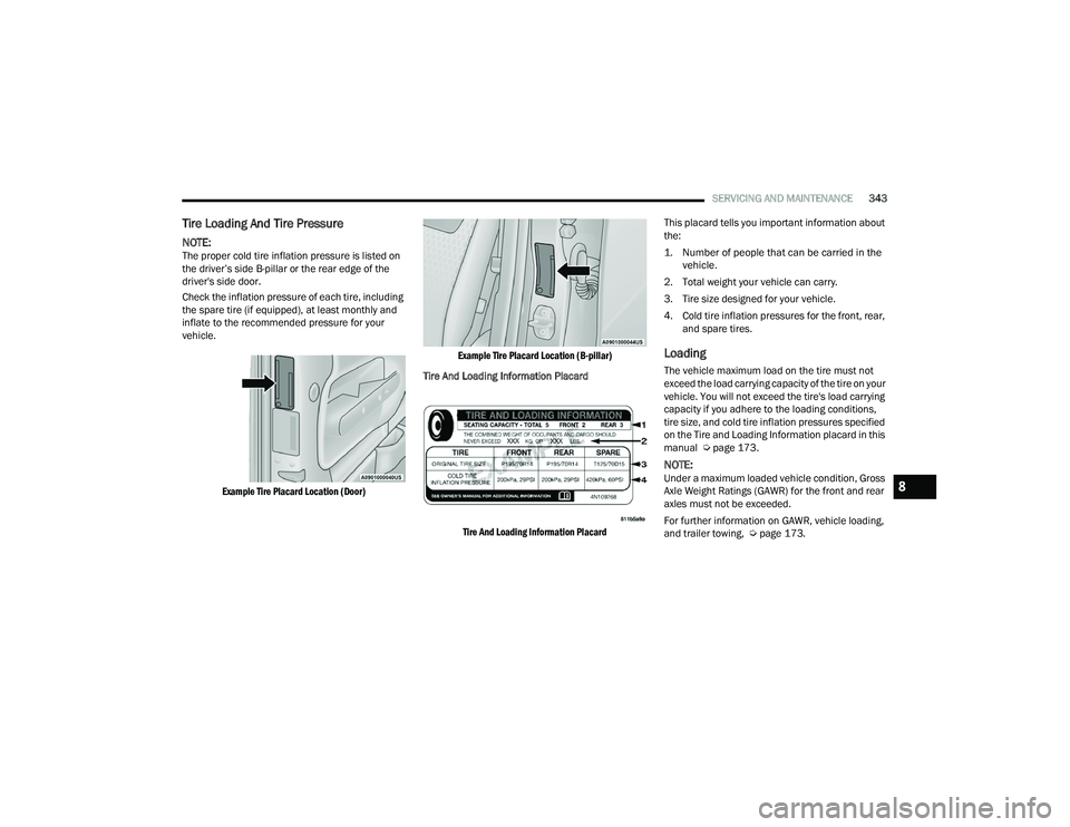
NOTE:The proper cold tire inflation pressure is listed on
the driver’s side B-pillar or the rear edge of the
driver's side door.
Check the inflation pressure of each tire, including
the spare tire (if equipped), at least monthly and
inflate to the recommended pressure for your
vehicle.
Example Tire Placard Location (Door) Example Tire Placard Location (B-pillar)
Tire And Loading Information Placard
Tire And Loading Information Placard
This placard tells you important information about
the:
1. Number of people that can be carried in the
vehicle.
2. Total weight your vehicle can carry.
3. Tire size designed for your vehicle.
4. Cold tire inflation pressures for the front, rear, and spare tires.
Loading
The vehicle maximum load on the tire must not
exceed the load carrying capacity of the tire on your
vehicle. You will not exceed the tire's load carrying
capacity if you adhere to the loading conditions,
tire size, and cold tire inflation pressures specified
on the Tire and Loading Information placard in this
manual Ú page 173.
NOTE:Under a maximum loaded vehicle condition, Gross
Axle Weight Ratings (GAWR) for the front and rear
axles must not be exceeded.
For further information on GAWR, vehicle loading,
and trailer towing, Ú page 173.8
22_RUP_OM_EN_USC_t.book Page 343
Page 353 of 384
SERVICING AND MAINTENANCE351
Spare Tire Matching Original Equipped Tire
And Wheel — If Equipped
Your vehicle may be equipped with a spare tire and
wheel equivalent in look and function to the
original equipment tire and wheel found on the
front or rear axle of your vehicle. This spare tire
may be used in the tire rotation for your vehicle. If
your vehicle has this option, refer to an authorized
tire dealer for the recommended tire rotation
pattern.
Compact Spare Tire — If Equipped
The compact spare is for temporary emergency
use only. You can identify if your vehicle is
equipped with a compact spare by looking at the
spare tire description on the Tire and Loading
Information Placard located on the driver’s side
door opening or on the sidewall of the tire.
Compact spare tire descriptions begin with the
letter “T” or “S” preceding the size designation.
Example: T145/80D18 103M.
T, S = Temporary Spare Tire
Since this tire has limited tread life, the original
equipment tire should be repaired (or replaced)
and reinstalled on your vehicle at the first
opportunity. Do not install a wheel cover or attempt to mount a
conventional tire on the compact spare wheel,
since the wheel is designed specifically for the
compact spare tire. Do not install more than one
compact spare tire and wheel on the vehicle at any
given time.
Collapsible Spare Tire — If Equipped
The collapsible spare is for temporary emergency
use only. You can identify if your vehicle is
equipped with a collapsible spare by looking at the
spare tire description on the Tire and Loading
Information Placard located on the driver’s side
door opening or on the sidewall of the tire.
Collapsible spare tire description
example: 165/80-17 101P.Since this tire has limited tread life, the original
equipment tire should be repaired (or replaced)
and reinstalled on your vehicle at the first
opportunity.
Inflate collapsible tire only after the wheel is
properly installed to the vehicle. Inflate the
collapsible tire using the electric air pump before
lowering the vehicle.
Do not install a wheel cover or attempt to mount a
conventional tire on the collapsible spare wheel,
since the wheel is designed specifically for the
collapsible spare tire.
WARNING!
Compact and collapsible spares are for
temporary emergency use only. With these
spares, do not drive more than 50 mph
(80 km/h). Temporary use spares have limited
tread life. When the tread is worn to the tread
wear indicators, the temporary use spare tire
needs to be replaced. Be sure to follow the
warnings, which apply to your spare. Failure to
do so could result in spare tire failure and loss of
vehicle control.
WARNING!
Compact and collapsible spares are for
temporary emergency use only. With these
spares, do not drive more than 50 mph
(80 km/h). Temporary use spares have limited
tread life. When the tread is worn to the tread
wear indicators, the temporary use spare tire
needs to be replaced. Be sure to follow the
warnings, which apply to your spare. Failure to
do so could result in spare tire failure and loss of
vehicle control.
8
22_RUP_OM_EN_USC_t.book Page 351
Page 354 of 384

352SERVICING AND MAINTENANCE
Full Size Spare — If Equipped
The full size spare is for temporary emergency use
only. This tire may look like the originally equipped
tire on the front or rear axle of your vehicle, but it is
not. This spare tire may have limited tread life.
When the tread is worn to the tread wear
indicators, the temporary use full size spare tire
needs to be replaced. Since it is not the same as
your original equipment tire, replace (or repair) the
original equipment tire and reinstall on the vehicle
at the first opportunity.
Limited Use Spare — If Equipped
The limited use spare tire is for temporary
emergency use only. This tire is identified by a label
located on the limited use spare wheel. This label
contains the driving limitations for this spare. This
tire may look like the original equipped tire on the
front or rear axle of your vehicle, but it is not.
Installation of this limited use spare tire affects
vehicle handling. Since it is not the same as your
original equipment tire, replace (or repair) the
original equipment tire and reinstall on the vehicle
at the first opportunity.
WHEEL AND WHEEL TRIM CARE
All wheels and wheel trim, especially aluminum
and chrome plated wheels, should be cleaned
regularly using mild (neutral Ph) soap and water to
maintain their luster and to prevent corrosion.
Wash wheels with the same soap solution
recommended for the body of the vehicle and
remember to always wash when the surfaces are
not hot to the touch. Your wheels are susceptible to deterioration
caused by salt, sodium chloride, magnesium
chloride, calcium chloride, etc., and other road
chemicals used to melt ice or control dust on dirt
roads. Use a soft cloth or sponge and mild soap to
wipe away promptly. Do not use harsh chemicals or
a stiff brush. They can damage the wheel’s
protective coating that helps keep them from
corroding and tarnishing.
WARNING!
Limited use spares are for emergency use only.
Installation of this limited use spare tire affects
vehicle handling. With this tire, do not drive
more than the speed listed on the limited use
spare wheel. Keep inflated to the cold tire
inflation pressures listed on your Tire and
Loading Information Placard located on the
driver’s side B-pillar or the rear edge of the
driver’s side door. Replace (or repair) the original
equipment tire at the first opportunity and
reinstall it on your vehicle. Failure to do so could
result in loss of vehicle control.
CAUTION!
Avoid products or automatic car washes that use
acidic solutions or strong alkaline additives or
harsh brushes. Many aftermarket wheel
cleaners and automatic car washes may
damage the wheel's protective finish. Such
damage is not covered by the New Vehicle
Limited Warranty. Only car wash soap, Mopar®
Wheel Cleaner or equivalent is recommended.
22_RUP_OM_EN_USC_t.book Page 352