2022 CHRYSLER PACIFICA towing
[x] Cancel search: towingPage 5 of 384

3
UNIVERSAL GARAGE DOOR OPENER
(HOMELINK®) ....................................................... 61 Before You Begin Programming
HomeLink®.......................................................61
Erasing All The HomeLink® Channels ............61
Identifying Whether You Have A Rolling
Code Or Non-Rolling Code Device ...................62
Programming HomeLink® To A Garage
Door Opener .....................................................62
Programming HomeLink® To A
Miscellaneous Device ......................................63
Reprogramming A Single HomeLink®
Button ...............................................................63
Canadian/Gate Operator Programming .........63
Security .............................................................64
Troubleshooting Tips ........................................64
EXTERIOR LIGHTS.................................................. 65
Multifunction Lever ..........................................65
Headlight Switch...............................................65
Daytime Running Lights (DRLs) —
If Equipped........................................................66
High/Low Beam Switch....................................66
Automatic High Beam — If Equipped .............66
Flash-To-Pass ...................................................67
Automatic Headlights — If Equipped ..............67
Headlights On With Wipers —
If Equipped........................................................67
Headlight Time Delay — If Equipped ...............67
Lights-On Reminder..........................................67 Front Fog Lights — If Equipped .......................68
Turn Signals ......................................................68
Lane Change Assist — If Equipped ..................68
Battery Saver ...................................................68
INTERIOR LIGHTS ..................................................69
Interior Courtesy Lights ...................................69
WINDSHIELD WIPER AND WASHERS .................70
Windshield Wiper Operation ............................70
Rain Sensing Wipers — If Equipped ................71
Rear Wiper And Washer...................................71
CLIMATE CONTROLS .............................................72
Automatic Climate Control Descriptions
And Functions ...................................................72
Manual Climate Control Descriptions
And Functions ...................................................77
Automatic Temperature Control (ATC) —
If Equipped .......................................................82
Climate Voice Commands................................83
Operating Tips .................................................83
INTERIOR STORAGE AND EQUIPMENT ............... 84
Storage..............................................................84
Sun Screens — If Equipped..............................87
USB/AUX Control ..............................................87
Power Outlets ...................................................89
Power Inverter — If Equipped .........................91
Wireless Charging Pad — If Equipped .............91 WINDOWS .............................................................. 92
Power Windows ................................................ 92
Automatic Window Features ........................... 93
Reset Auto-Up................................................... 93
Wind Buffeting.................................................. 94
PANORAMIC SUNROOF — IF EQUIPPED ............. 94
Opening And Closing The Sunroof .................. 94
Opening And Closing The Power
Sunshade — If Equipped .................................. 95
Pinch Protect Feature ...................................... 95
Venting Sunroof................................................ 95
Ignition Off Operation....................................... 96
Sunroof Maintenance ...................................... 96
HOOD....................................................................... 96
Opening............................................................. 96
Closing ..............................................................96
LIFTGATE ................................................................. 97
To Unlock/Open The Liftgate .......................... 97
To Lock/Close The Liftgate.............................. 97
Power Liftgate — If Equipped........................... 97
Hands-Free Liftgate — If Equipped.................. 99
Cargo Area Features ................................. 100
STOW ‘N PLACE ROOF RACK —
IF EQUIPPED ........................................................ 106
Deploying The Crossbars .............................. 106
Stowing The Crossbars ................................. 108
22_RUP_OM_EN_USC_t.book Page 3
Page 7 of 384

5
PARKSENSE FRONT/REAR PARK ASSIST
SYSTEM — IF EQUIPPED .................................... 156 ParkSense Sensors ....................................... 157
ParkSense Display ........................................ 157
ParkSense Warning Display.......................... 160
Enabling And Disabling ParkSense .............. 160
Service The ParkSense Park Assist
System ........................................................... 160Cleaning The ParkSense System ................. 161ParkSense System Usage Precautions ........ 161
PARKSENSE ACTIVE PARK ASSIST
SYSTEM — IF EQUIPPED ..................................... 162
Enabling And Disabling The ParkSense
Active Park Assist System ............................. 162
Parallel/Perpendicular Parking Space
Assistance Operation .................................... 163 LANESENSE — IF EQUIPPED ............................. 166
LaneSense Operation ................................... 166Turning LaneSense On Or Off ....................... 166
LaneSense Warning Message ...................... 166Changing LaneSense Status ........................ 168
PARKVIEW REAR BACK UP CAMERA .............. 168
SURROUND VIEW CAMERA SYSTEM —
IF EQUIPPED ....................................................... 169
FAMCAM SYSTEM — IF EQUIPPED.................... 171
REFUELING THE VEHICLE ................................... 172
VEHICLE LOADING .............................................. 173 Certification Label ......................................... 173
TRAILER TOWING ................................................ 174
Common Towing Definitions......................... 174
Trailer Hitch Classification ............................ 176
Trailer Towing Weights (Maximum
Trailer Weight Ratings).................................. 177
Vehicle Loading Chart ................................... 178Trailer And Tongue Weight ........................... 180Towing Requirements .................................. 180
Towing Tips ................................................... 183 RECREATIONAL TOWING
(BEHIND MOTORHOME) ..................................... 184
Towing This Vehicle Behind Another
Vehicle ........................................................... 184
DRIVING TIPS ....................................................... 185
Driving On Slippery Surfaces ........................ 185Driving Through Water ................................. 186
MULTIMEDIA
UCONNECT SYSTEMS ......................................... 187
CYBERSECURITY ................................................. 187
UCONNECT SETTINGS ......................................... 188 Customer Programmable Features ............ 188
REAR SEAT ENTERTAINMENT WITH
AMAZON FIRE TV BUILT-IN —
IF EQUIPPED ......................................................... 213
Overview ........................................................ 213
Getting Started .............................................. 213
Accessing Rear Seat Entertainment
with Fire TV Built-in from the Front
Radio Screen ................................................. 213
22_RUP_OM_EN_USC_t.book Page 5
Page 9 of 384

7
JUMP STARTING................................................... 300 Preparations For Jump Start......................... 301Jump Starting Procedure .............................. 301
REFUELING IN EMERGENCY –
IF EQUIPPED ......................................................... 302
IF YOUR ENGINE OVERHEATS ............................ 303
MANUAL PARK RELEASE .................................. 304
FREEING A STUCK VEHICLE .............................. 305
TOWING A DISABLED VEHICLE .......................... 306
All Wheel Drive (AWD) Models ...................... 308
ENHANCED ACCIDENT RESPONSE SYSTEM
(EARS) .................................................................. 308
EVENT DATA RECORDER (EDR) ......................... 308
SERVICING AND MAINTENANCE
SCHEDULED SERVICING ..................................... 309
Maintenance Plan ......................................... 310
ENGINE COMPARTMENT .................................... 313
3.6L Engine.................................................... 313
Checking Oil Level ......................................... 314
Adding Washer Fluid .................................... 314
Maintenance-Free Battery ........................... 314
Pressure Washing ......................................... 315 VEHICLE MAINTENANCE..................................... 315
Engine Oil ...................................................... 315
Engine Oil Filter ............................................. 316Engine Air Cleaner Filter ............................... 316
Accessory Drive Belt Inspection ................... 317Air Conditioner Maintenance........................ 317
Body Lubrication ........................................... 320Windshield Wiper Blades.............................. 320Exhaust System ............................................ 323
Cooling System .............................................. 324
Brake System ............................................... 327
Automatic Transmission .............................. 328Fuses.............................................................. 329
Bulb Replacement......................................... 337
TIRES ................................................................... 339
Tire Safety Information ................................. 339
Tires — General Information ......................... 346
Tire Types....................................................... 350
Spare Tires — If Equipped ............................ 350
Wheel And Wheel Trim Care ........................ 352
Snow Traction Devices ................................. 353
Tire Rotation Recommendations ................. 355 DEPARTMENT OF TRANSPORTATION
UNIFORM TIRE QUALITY GRADES .................... 355
Treadwear...................................................... 356
Traction Grades ............................................. 356Temperature Grades..................................... 356
STORING THE VEHICLE ....................................... 357
BODYWORK .......................................................... 357
Protection From Atmospheric Agents ......... 357
Body And Underbody Maintenance ............. 357
Preserving The Bodywork ............................. 357
INTERIORS ........................................................... 358
Seats And Fabric Parts ................................. 358
Plastic And Coated Parts .............................. 359
Leather Surfaces........................................... 359
Glass Surfaces ............................................. 359TECHNICAL SPECIFICATIONS
VEHICLE IDENTIFICATION NUMBER
(VIN) ....................................................................... 360
BRAKE SYSTEM ................................................... 360
WHEEL AND TIRE TORQUE
SPECIFICATIONS .................................................. 360Torque Specifications ................................... 360
22_RUP_OM_EN_USC_t.book Page 7
Page 52 of 384

50GETTING TO KNOW YOUR VEHICLE
Third Row Power Stow ‘n Go Seat —
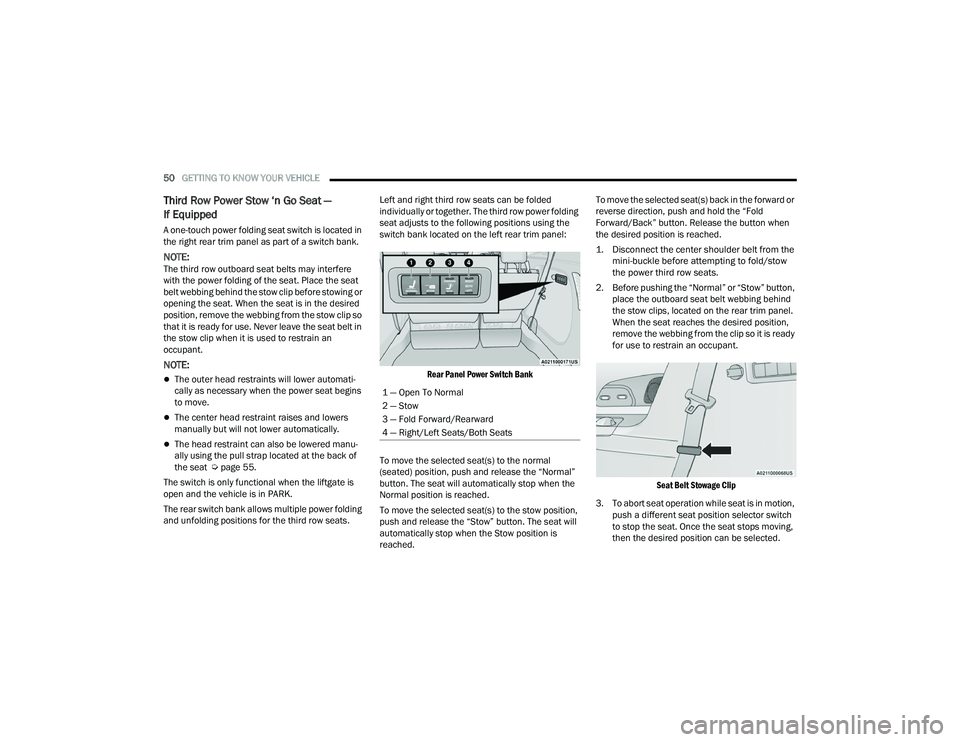
If Equipped
A one-touch power folding seat switch is located in
the right rear trim panel as part of a switch bank.
NOTE:The third row outboard seat belts may interfere
with the power folding of the seat. Place the seat
belt webbing behind the stow clip before stowing or
opening the seat. When the seat is in the desired
position, remove the webbing from the stow clip so
that it is ready for use. Never leave the seat belt in
the stow clip when it is used to restrain an
occupant.
NOTE:
The outer head restraints will lower automati -
cally as necessary when the power seat begins
to move.
The center head restraint raises and lowers
manually but will not lower automatically.
The head restraint can also be lowered manu -
ally using the pull strap located at the back of
the seat Ú page 55.
The switch is only functional when the liftgate is
open and the vehicle is in PARK.
The rear switch bank allows multiple power folding
and unfolding positions for the third row seats. Left and right third row seats can be folded
individually or together. The third row power folding
seat adjusts to the following positions using the
switch bank located on the left rear trim panel:
Rear Panel Power Switch Bank
To move the selected seat(s) to the normal
(seated) position, push and release the “Normal”
button. The seat will automatically stop when the
Normal position is reached.
To move the selected seat(s) to the stow position,
push and release the “Stow” button. The seat will
automatically stop when the Stow position is
reached. To move the selected seat(s) back in the forward or
reverse direction, push and hold the “Fold
Forward/Back” button. Release the button when
the desired position is reached.
1. Disconnect the center shoulder belt from the
mini-buckle before attempting to fold/stow
the power third row seats.
2. Before pushing the “Normal” or “Stow” button, place the outboard seat belt webbing behind
the stow clips, located on the rear trim panel.
When the seat reaches the desired position,
remove the webbing from the clip so it is ready
for use to restrain an occupant.
Seat Belt Stowage Clip
3. To abort seat operation while seat is in motion, push a different seat position selector switch
to stop the seat. Once the seat stops moving,
then the desired position can be selected.
1 — Open To Normal
2 — Stow
3 — Fold Forward/Rearward
4 — Right/Left Seats/Both Seats
22_RUP_OM_EN_USC_t.book Page 50
Page 110 of 384

108GETTING TO KNOW YOUR VEHICLE
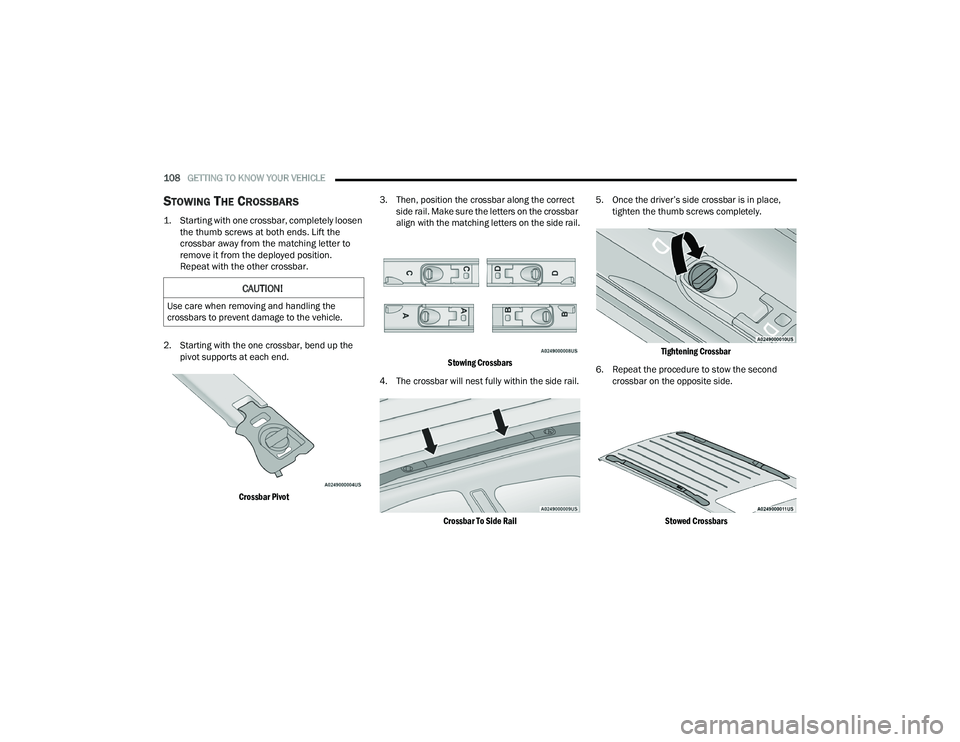
STOWING THE CROSSBARS
1. Starting with one crossbar, completely loosen
the thumb screws at both ends. Lift the
crossbar away from the matching letter to
remove it from the deployed position.
Repeat with the other crossbar.
2. Starting with the one crossbar, bend up the pivot supports at each end.
Crossbar Pivot
3. Then, position the crossbar along the correct
side rail. Make sure the letters on the crossbar
align with the matching letters on the side rail.
Stowing Crossbars
4. The crossbar will nest fully within the side rail.
Crossbar To Side Rail
5. Once the driver’s side crossbar is in place,
tighten the thumb screws completely.
Tightening Crossbar
6. Repeat the procedure to stow the second crossbar on the opposite side.
Stowed Crossbars
CAUTION!
Use care when removing and handling the
crossbars to prevent damage to the vehicle.
22_RUP_OM_EN_USC_t.book Page 108
Page 122 of 384

120GETTING TO KNOW YOUR INSTRUMENT PANEL
NOTE:
The charging system is independent from load
reduction. The charging system performs a diag-
nostic on the charging system continuously.
If the Battery Charge Warning Light is on it may
indicate a problem with the charging system
Ú page 121.
The electrical loads that may be switched off (if
equipped), and vehicle functions which can be
effected by load reduction:
Heated Seat/Vented Seats/Heated Wheel
Heated/Cooled Cup Holders — If Equipped
Rear Defroster And Heated Mirrors
HVAC System
115 Volts AC Power Inverter System
Audio and Telematics System
Loss of the battery charge may indicate one or
more of the following conditions:
The charging system cannot deliver enough
electrical power to the vehicle system because
the electrical loads are larger than the capability
of charging system. The charging system is still
functioning properly.
Turning on all possible vehicle electrical loads
(e.g. HVAC to max settings, exterior and interior
lights, overloaded power outlets +12 Volts,
150W, USB ports) during certain driving condi -
tions (city driving, towing, frequent stopping).
Installing options like additional lights, upfitter
electrical accessories, audio systems, alarms
and similar devices.
Unusual driving cycles (short trips separated by
long parking periods).
The vehicle was parked for an extended period
of time (weeks, months).
The battery was recently replaced and was not
charged completely.
The battery was discharged by an electrical load
left on when the vehicle was parked.
The battery was used for an extended period
with the engine not running to supply radio,
lights, chargers, +12 Volt portable appliances
like vacuum cleaners, game consoles and
similar devices. What to do when an electrical load reduction
action message is present (“Battery Saver On” or
“Battery Saver Mode”)
During a trip:
Reduce power to unnecessary loads if possible:
Turn off redundant lights (interior or exterior)
Check what may be plugged in to power
outlets +12 Volts, 150W, USB ports
Check HVAC settings (blower, temperature)
Check the audio settings (volume)
After a trip:
Check if any aftermarket equipment was
installed (additional lights, upfitter electrical
accessories, audio systems, alarms) and review
specifications if any (load and Ignition Off Draw
currents).
Evaluate the latest driving cycles (distance,
driving time and parking time).
The vehicle should have service performed if
the message is still present during consecutive
trips and the evaluation of the vehicle and
driving pattern did not help to identify the cause.
22_RUP_OM_EN_USC_t.book Page 120
Page 125 of 384

GETTING TO KNOW YOUR INSTRUMENT PANEL123
Electronic Throttle Control (ETC) Warning
Light
This warning light will illuminate to
indicate a problem with the ETC system.
If a problem is detected while the vehicle
is running, the light will either stay on or
flash depending on the nature of the problem.
Cycle the ignition when the vehicle is safely and
completely stopped and the transmission is placed
in the PARK (P) position. The light should turn off.
If the light remains on with the vehicle running,
your vehicle will usually be drivable; however, see
an authorized dealer for service as soon as
possible.
NOTE:This light may turn on if the accelerator and brake
pedals are pressed at the same time.
If the light continues to flash when the vehicle is
running, immediate service is required and you
may experience reduced performance, an
elevated/rough idle, or engine stall and your
vehicle may require towing. The light will come on
when the ignition is placed in the ON/RUN or ACC/
ON/RUN position and remain on briefly as a bulb
check. If the light does not come on during starting,
have the system checked by an authorized dealer.
Engine Coolant Temperature Warning
Light
This warning light warns of an
overheated engine condition. If the
engine coolant temperature is too high,
this indicator will illuminate and a single
chime will sound. If the temperature reaches the
upper limit, a continuous chime will sound for
four minutes or until the engine is able to cool;
whichever comes first.
If the light turns on while driving, safely pull over
and stop the vehicle. If the Air Conditioning (A/C)
system is on, turn it off. Also, shift the transmission
into NEUTRAL (N) and idle the vehicle. If the
temperature reading does not return to normal,
turn the engine off immediately and call for service
Ú page 303.
Hood Open Warning Light
This warning light will illuminate when the
hood is left open and not fully closed.
NOTE:If the vehicle is moving, there will also be a single
chime.
Liftgate Open Warning Light
This warning light will illuminate when the
liftgate is open.
NOTE:If the vehicle is moving, there will also be a single
chime.
Oil Pressure Warning Light
This warning light will illuminate to
indicate low engine oil pressure. If the
light turns on while driving, stop the
vehicle, shut off the engine as soon as
possible, and contact an authorized dealer.
A chime will sound when this light turns on.
Do not operate the vehicle until the cause is
corrected. This light does not indicate how much oil
is in the engine. The engine oil level must be
checked under the hood.
Oil Temperature Warning Light
This warning light will illuminate to
indicate the engine oil temperature is
high. If the light turns on while driving,
stop the vehicle and shut off the engine
as soon as possible. Wait for oil temperature to
return to normal levels.
3
22_RUP_OM_EN_USC_t.book Page 123
Page 126 of 384

124GETTING TO KNOW YOUR INSTRUMENT PANEL
Seat Belt Reminder Warning Light
This warning light indicates when the
driver or passenger seat belt is
unbuckled. When the ignition is first
placed in the ON/RUN or ACC/ON/RUN
position and if the driver’s seat belt is unbuckled,
a chime will sound and the light will turn on. When
driving, if the driver or front passenger seat belt
remains unbuckled, the Seat Belt Reminder Light
will flash or remain on continuously and a chime
will sound Ú page 239.
Transmission Temperature Warning
Light — If Equipped
This warning light will illuminate to warn
of a high transmission fluid temperature.
This may occur with strenuous usage
such as trailer towing. If this light turns
on, stop the vehicle and run the engine at idle or
slightly faster, with the transmission in PARK (P) or
NEUTRAL (N), until the light turns off. Once the light
turns off, you may continue to drive normally.
Vehicle Security Warning Light —
If Equipped
This warning light will flash at a fast rate
for approximately 15 seconds when the
vehicle security system is arming, and
then will flash slowly until the vehicle is
disarmed.
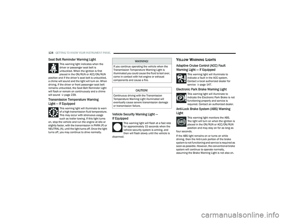
YELLOW WARNING LIGHTS
Adaptive Cruise Control (ACC) Fault
Warning Light — If Equipped
This warning light will illuminate to
indicate a fault in the ACC system.
Contact a local authorized dealer for
service Ú page 147.
Electronic Park Brake Warning Light
This warning light will illuminate to
indicate the Electronic Park Brake is not
functioning properly and service is
required. Contact an authorized dealer.
Anti-Lock Brake System (ABS) Warning
Light
This warning light monitors the ABS.
The light will turn on when the ignition is
placed in the ON/RUN or ACC/ON/RUN
position and may stay on for as long as
four seconds.
If the ABS light remains on or turns on while
driving, then the Anti-Lock portion of the brake
system is not functioning and service is required as
soon as possible. However, the conventional brake
system will continue to operate normally,
assuming the Brake Warning Light is not also on.
WARNING!
If you continue operating the vehicle when the
Transmission Temperature Warning Light is
illuminated you could cause the fluid to boil over,
come in contact with hot engine or exhaust
components and cause a fire.
CAUTION!
Continuous driving with the Transmission
Temperature Warning Light illuminated will
eventually cause severe transmission damage
or transmission failure.
22_RUP_OM_EN_USC_t.book Page 124