2022 CHRYSLER PACIFICA lock
[x] Cancel search: lockPage 295 of 384

IN CASE OF EMERGENCY293
5. Lower the vehicle to the ground by turning the jack handle counterclockwise.
6. Finish tightening the lug nuts. Push down on the wrench while at the end of the handle for
increased leverage. Tighten the lug nuts in a
star pattern until each nut has been tightened
twice Ú page 360. If in doubt about the
correct tightness, have them checked with a
torque wrench by an authorized dealer or at a
service station.
7. After 25 miles (40 km) check the lug nut torque with a torque wrench to ensure that all
lug nuts are properly seated against the wheel.
PORTABLE AIR COMPRESSOR —
I
F EQUIPPED
Your vehicle may be equipped with a Portable Air
Compressor. Use the Portable Air Compressor
located in the side compartment of the cargo area
to inflate the inflatable tire to 60 psi (4.2 Bar).
Portable Air Compressor
Portable Air Compressor Usage With Inflatable
Spare Tire
1. Remove the Portable Air Compressor from the storage location.
2. Raise the vehicle as described in
the Jacking Instructions within this
section. 3. Install the Inflatable Spare tire as
described in the Jack Instructions
section in this manual. Make sure
that the valve stem is located near
the ground, and then screw the air hose of the
Portable Air Compressor to the valve stem.
4. Uncoil the power plug and connect
it the vehicles 12 Volt power Outlet.
5. Always start the engine before
turning ON the Portable Air
Compressor.
6. Switch the power button ON.
7. Inflate the tire to 60 psi (4.2 Bar)
recommended as per the label on
the wheel or if the vehicle equipped
with the inflatable spare tire
pressure indicated on the Tire and Loading
information label located on the driver-side
door opening.
NOTE:If the tire is overinflated, use the deflation button
to reduce the tire air pressure.
1 — Power Plug
2 — Deflation Button
3 — Pressure Gauge
4 — Power Button
5 — Air Hose
7
22_RUP_OM_EN_USC_t.book Page 293
Page 306 of 384

304IN CASE OF EMERGENCY
MANUAL PARK RELEASE
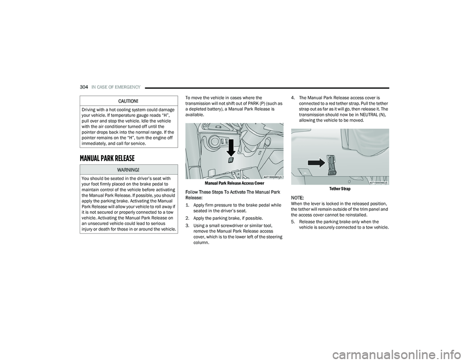
To move the vehicle in cases where the
transmission will not shift out of PARK (P) (such as
a depleted battery), a Manual Park Release is
available.
Manual Park Release Access Cover
Follow These Steps To Activate The Manual Park
Release:
1. Apply firm pressure to the brake pedal while seated in the driver’s seat.
2. Apply the parking brake, if possible.
3. Using a small screwdriver or similar tool, remove the Manual Park Release access
cover, which is to the lower left of the steering
column. 4. The Manual Park Release access cover is
connected to a red tether strap. Pull the tether
strap out as far as it will go, then release it. The
transmission should now be in NEUTRAL (N),
allowing the vehicle to be moved.
Tether Strap
NOTE:When the lever is locked in the released position,
the tether will remain outside of the trim panel and
the access cover cannot be reinstalled.
5. Release the parking brake only when the vehicle is securely connected to a tow vehicle.
CAUTION!
Driving with a hot cooling system could damage
your vehicle. If temperature gauge reads “H”,
pull over and stop the vehicle. Idle the vehicle
with the air conditioner turned off until the
pointer drops back into the normal range. If the
pointer remains on the “H”, turn the engine off
immediately, and call for service.
WARNING!
You should be seated in the driver’s seat with
your foot firmly placed on the brake pedal to
maintain control of the vehicle before activating
the Manual Park Release. If possible, you should
apply the parking brake. Activating the Manual
Park Release will allow your vehicle to roll away if
it is not secured or properly connected to a tow
vehicle. Activating the Manual Park Release on
an unsecured vehicle could lead to serious
injury or death for those in or around the vehicle.
22_RUP_OM_EN_USC_t.book Page 304
Page 322 of 384

320SERVICING AND MAINTENANCE
BODY LUBRICATION
Locks and all body pivot points, including such
items as seat tracks, door hinge pivot points and
rollers, liftgate, tailgate, decklid, sliding doors and
hood hinges, should be lubricated periodically. Use
a lithium-based grease, such as Mopar® Spray
White Lube to ensure quiet, easy operation and to
protect against rust and wear. Prior to the
application of any lubricant, the parts concerned
should be wiped clean to remove dust and grit;
after lubricating, excess oil and grease should be
removed. Particular attention should also be given
to hood latching components to ensure proper
function. When performing other underhood
services, the hood latch release mechanism, and
safety catch should be cleaned and lubricated.
The external lock cylinders should be lubricated
twice a year, preferably in the Autumn and Spring.
Apply a small amount of a high quality lubricant,
such as Mopar® Lock Cylinder Lubricant directly
into the lock cylinder.
WINDSHIELD WIPER BLADES
Clean the rubber edges of the wiper blades and the
windshield periodically with a sponge or soft cloth
and a mild nonabrasive cleaner. This will remove
accumulations of salt or road film. Operation of the wipers on dry glass for long
periods may cause deterioration of the wiper
blades. Always use washer fluid when using the
wipers to remove salt or dirt from a dry windshield.
Avoid using the wiper blades to remove frost or ice
from the windshield. Keep the blade rubber out of
contact with petroleum products such as engine
oil, gasoline, etc.
NOTE:Life expectancy of wiper blades varies depending
on geographical area and frequency of use. If chat
-
tering, marks, water lines or wet spots are present,
clean the wiper blades or replace as necessary.
The wiper blades and wiper arms should be
inspected periodically, not just when wiper
performance problems are experienced. This
inspection should include the following points:
Wear or uneven edges
Foreign material
Hardening or cracking
Deformation or fatigue
If a wiper blade or wiper arm is damaged, replace
the affected wiper arm or blade with a new unit. Do
not attempt to repair a wiper arm or blade that is
damaged.
Front Wiper Blade Removal/Installation
1. Lift the wiper arm to raise the wiper blade off of the glass, until the wiper arm is in the full
up position.
Wiper Blade With Release Tab In Locked Position
CAUTION!
Do not allow the wiper arm to spring back
against the glass without the wiper blade in
place or the glass may be damaged.
1 — Wiper Blade
2 — Release Tab
3 — Wiper Arm
22_RUP_OM_EN_USC_t.book Page 320
Page 323 of 384

SERVICING AND MAINTENANCE321
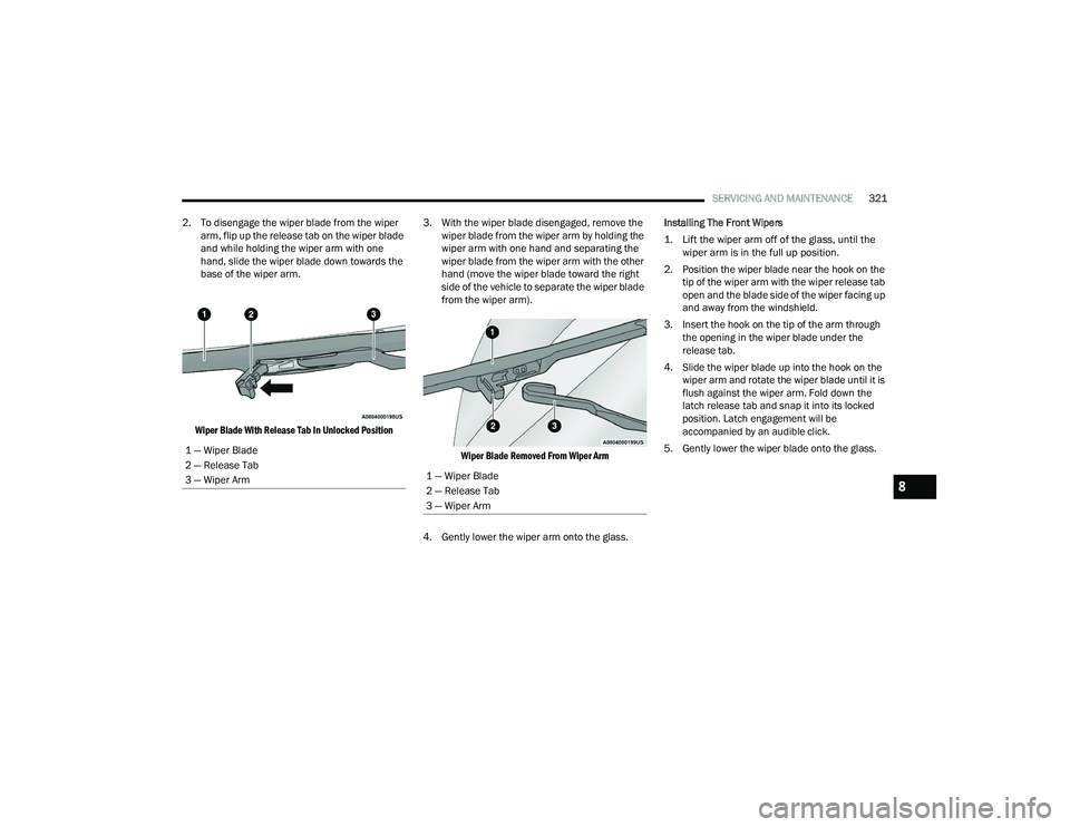
2. To disengage the wiper blade from the wiper arm, flip up the release tab on the wiper blade
and while holding the wiper arm with one
hand, slide the wiper blade down towards the
base of the wiper arm.
Wiper Blade With Release Tab In Unlocked Position
3. With the wiper blade disengaged, remove the
wiper blade from the wiper arm by holding the
wiper arm with one hand and separating the
wiper blade from the wiper arm with the other
hand (move the wiper blade toward the right
side of the vehicle to separate the wiper blade
from the wiper arm).
Wiper Blade Removed From Wiper Arm
4. Gently lower the wiper arm onto the glass. Installing The Front Wipers
1. Lift the wiper arm off of the glass, until the
wiper arm is in the full up position.
2. Position the wiper blade near the hook on the tip of the wiper arm with the wiper release tab
open and the blade side of the wiper facing up
and away from the windshield.
3. Insert the hook on the tip of the arm through the opening in the wiper blade under the
release tab.
4. Slide the wiper blade up into the hook on the wiper arm and rotate the wiper blade until it is
flush against the wiper arm. Fold down the
latch release tab and snap it into its locked
position. Latch engagement will be
accompanied by an audible click.
5. Gently lower the wiper blade onto the glass.
1 — Wiper Blade
2 — Release Tab
3 — Wiper Arm
1 — Wiper Blade
2 — Release Tab
3 — Wiper Arm8
22_RUP_OM_EN_USC_t.book Page 321
Page 324 of 384

322SERVICING AND MAINTENANCE
Rear Wiper Blade Removal/Installation
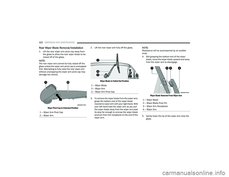
1. Lift the rear wiper arm pivot cap away from
the glass to allow the rear wiper blade to be
raised off of the glass.
NOTE:The rear wiper arm cannot be fully raised off the
glass unless the wiper arm pivot cap is unsnapped
first. Attempting to fully raise the rear wiper arm
without unsnapping the wiper arm pivot cap may
damage the vehicle.
Wiper Pivot Cap In Unlocked Position
2. Lift the rear wiper arm fully off the glass.
Wiper Blade In Folded Out Position
3. To remove the wiper blade from the wiper arm, grasp the bottom end of the wiper blade
nearest to wiper arm with your right hand. With
your left hand hold the wiper arm as you pull
the wiper blade away from the wiper arm past
its stop far enough to unsnap the wiper blade
pivot pin from the receptacle on the end of the
wiper arm.
NOTE:Resistance will be accompanied by an audible
snap.
4. Still grasping the bottom end of the wiper blade, move the wiper blade upward and away
from the wiper arm to disengage.
Wiper Blade Removed From Wiper Arm
5. Gently lower the tip of the wiper arm onto the glass.
1 — Wiper Arm Pivot Cap
2 — Wiper Arm
1 — Wiper Blade
2 — Wiper Arm
3 — Wiper Arm Pivot Cap
1 — Wiper Blade
2 — Wiper Blade Pivot Pin
3 — Wiper Arm Receptacle
4 — Wiper Arm
22_RUP_OM_EN_USC_t.book Page 322
Page 331 of 384

SERVICING AND MAINTENANCE329
FUSES
General Information
The fuses protect electrical systems against
excessive current. When a device does not work, you must check the
fuse element inside the blade fuse for a break/
melt.
Also, please be aware that using power outlets for
extended periods of time with the engine off may
result in vehicle battery discharge.
Blade Fuses
Underhood Fuses
The Power Distribution Center (PDC) is located in
the engine compartment near the battery. This
center contains cartridge fuses, mini-fuses,
micro-fuses, circuit breakers and relays. A label
that identifies each component is printed on the
inside of the cover.
Before any procedure is done on the PDC, make
sure engine is turned off.
Remove the cover by unlatching the two locks
located at each side of the PDC cover, avoid using
screwdrivers or any other tool to remove the cover,
since they may apply excessive force and result in
a broken/damaged part.
After service is done, secure the cover with its two
locks.
NOTE:The function and amperage of the following fuses
are different, depending on vehicle trim level and
content.
WARNING!
When replacing a blown fuse, always use an
appropriate replacement fuse with the same
amp rating as the original fuse. Never replace
a fuse with another fuse of higher amp rating.
Never replace a blown fuse with metal wires or
any other material. Do not place a fuse inside
a circuit breaker cavity or vice versa. Failure to
use proper fuses may result in serious
personal injury, fire and/or property damage.
Before replacing a fuse, make sure that the
ignition is off and that all the other services
are switched off and/or disengaged.
If the replaced fuse blows again, contact an
authorized dealer.
If a general protection fuse for safety systems
(air bag system, braking system), power unit
systems (engine system, transmission
system) or steering system blows, contact an
authorized dealer.
1 — Fuse Element
2 — Blade Fuse with a good/functional fuse
element
3 — Blade fuse with a bad/not functional fuse
element (blown fuse)CAUTION!
When installing the power distribution center
cover, it is important to ensure the cover is
properly positioned and fully latched. Failure to
do so may allow water to get into the power
distribution center and possibly result in an
electrical system failure.8
22_RUP_OM_EN_USC_t.book Page 329
Page 333 of 384

SERVICING AND MAINTENANCE331
F15 40 Amp Green –CBC / Power Locks
F16 –20 Amp Yellow ECM
F17 30 Amp Pink –Starter
F18 40 Amp Green –CBC / EXT LIGHTS
F19 25 Amp Clear –2nd Row Folding Seats Solenoid LT *
F20 –10 Amp Red A/C Compressor Clutch
F21 25 Amp Clear –2nd Row Folding Seat Solenoid RT *
F22 ––Not Populated
F23 ––Not Populated
F24 –20 Amp Yellow RR Wiper
F25 –10 Amp RedHands Free Dr Mod / Active Grille
Shutter / Pwr Mirror / VRM
F26 40 Amp Green –Front HVAC Blower Motor
F27 25 Amp Clear –RR Slide Door Module-RT *
F28 –10 Amp RedDiagnostic Port / USB+(IP) / Video
USB Port / Overhead DVD Player(Aftermarket)
F29 ––Not Populated
F30 –15 Amp BlueMedia HUB / Power Lumbar *
F31 ––Not Populated
F32 20 Amp Blue –ECM
CavityCartridge Fuse Blade FuseDescription
*If Equipped
8
22_RUP_OM_EN_USC_t.book Page 331
Page 335 of 384

SERVICING AND MAINTENANCE333
F53 ––Not Populated
F54 40 Amp Green –ESP-ECU And Valves
F55 –15 Amp BlueRadio Frequency HUB/ Keyless
Ignition System (KIN) / ESL / DVD
F56 –10 Amp RedFront and Rear HVAC Control
Module / Occupant Classification
Module (OCM) / Electronic Steering Lock (ESL) / ESP / ESC
F57 ––Not Populated
F58 –10 Amp RedDrive Train Control Mod / Power
Transfer Unit *
F59 30 Amp Pink –Trailer Tow Receptacle *
F60 –20 Amp Yellow Rear Cargo Pwr Outlet
F61 –20 Amp YellowTrailer Tow Right Stop/Turn *
F62 –20 Amp Yellow Power Transfer Unit *
F63 –20 Amp Yellow Trailer Tow Left Stop/Turn *
F64 –15 Amp Blue RT HID Headlamp *
F65 ––Not Populated
F66 –15 Amp Blue Cluster
F67 –10 Amp RedHaptic Lane Feedback Module
(HALF) / Parktronics System (PTS)/
Drivers Assist System Module (DASM)
Cavity Cartridge Fuse Blade FuseDescription
*If Equipped
8
22_RUP_OM_EN_USC_t.book Page 333