2022 CHRYSLER PACIFICA center console
[x] Cancel search: center consolePage 60 of 384

58GETTING TO KNOW YOUR VEHICLE
ILLUMINATED VANITY MIRRORS —
I
F EQUIPPED
To access an illuminated vanity mirror, flip down
one of the visors and lift the cover.
Illuminated Mirror
OUTSIDE MIRRORS
The outside mirror(s) can be adjusted to the center
of the adjacent lane of traffic to achieve the
optimal view.
DRIVER'S OUTSIDE AUTOMATIC
D
IMMING MIRROR — IF EQUIPPED
The driver’s outside mirror will automatically adjust
for glare from vehicles behind you. This feature is
controlled by the inside automatic dimming mirror
and will automatically adjust for headlight glare
when the inside mirror adjusts.
CONVERSATION MIRROR
Located in the overhead console there is a
conversation mirror to view all the passengers in
the vehicle. Push the panel to release the drop
down mirror. Raise the mirror and push to latch it
back in the stowed position.
Conversation Mirror
WARNING!
Vehicles and other objects seen in an outside
convex mirror will look smaller and farther away
than they really are. Relying too much on side
convex mirrors could cause you to collide with
another vehicle or other object. Use your inside
mirror when judging the size or distance of a
vehicle seen in a side convex mirror.
22_RUP_OM_EN_USC_t.book Page 58
Page 63 of 384

GETTING TO KNOW YOUR VEHICLE61
UNIVERSAL GARAGE DOOR OPENER
(HOMELINK®)
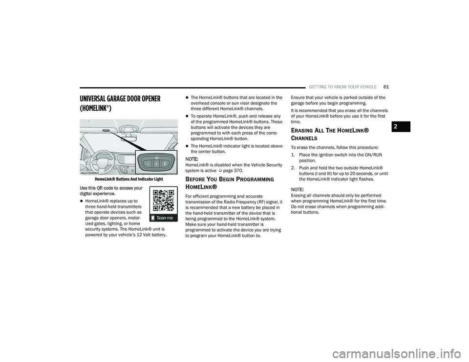
HomeLink® Buttons And Indicator Light
Use this QR code to access your
digital experience.
HomeLink® replaces up to
three hand-held transmitters
that operate devices such as
garage door openers, motor -
ized gates, lighting, or home
security systems. The HomeLink® unit is
powered by your vehicle’s 12 Volt battery.
The HomeLink® buttons that are located in the
overhead console or sun visor designate the
three different HomeLink® channels.
To operate HomeLink®, push and release any
of the programmed HomeLink® buttons. These
buttons will activate the devices they are
programmed to with each press of the corre -
sponding HomeLink® button.
The HomeLink® indicator light is located above
the center button.
NOTE:HomeLink® is disabled when the Vehicle Security
system is active Ú page 370.
BEFORE YOU BEGIN PROGRAMMING
H
OMELINK®
For efficient programming and accurate
transmission of the Radio Frequency (RF) signal, it
is recommended that a new battery be placed in
the hand-held transmitter of the device that is
being programmed to the HomeLink® system.
Make sure your hand-held transmitter is
programmed to activate the device you are trying
to program your HomeLink® button to. Ensure that your vehicle is parked outside of the
garage before you begin programming.
It is recommended that you erase all the channels
of your HomeLink® before you use it for the first
time.
ERASING ALL THE HOMELINK®
C
HANNELS
To erase the channels, follow this procedure:
1. Place the ignition switch into the ON/RUN
position.
2. Push and hold the two outside HomeLink® buttons (I and III) for up to 20 seconds, or until
the HomeLink® indicator light flashes.
NOTE:Erasing all channels should only be performed
when programming HomeLink® for the first time.
Do not erase channels when programming addi -
tional buttons.
2
22_RUP_OM_EN_USC_t.book Page 61
Page 86 of 384

84GETTING TO KNOW YOUR VEHICLE
INTERIOR STORAGE AND EQUIPMENT
STORAGE
Glove Compartment
The glove compartment is located on the
passenger side of the instrument panel.
To open the glove compartment, pull the release
handle.
Release Handle
Front Door Storage
Both interior front door panels have multiple
pockets for storage.
Overhead Sunglass Storage
At the front of the overhead console, a
compartment is provided for the storage of one
pair of sunglasses.
From the closed position, push the indentation to
open the compartment.
Overhead Sunglass Door Latch
The door will slowly rotate to the full open position.
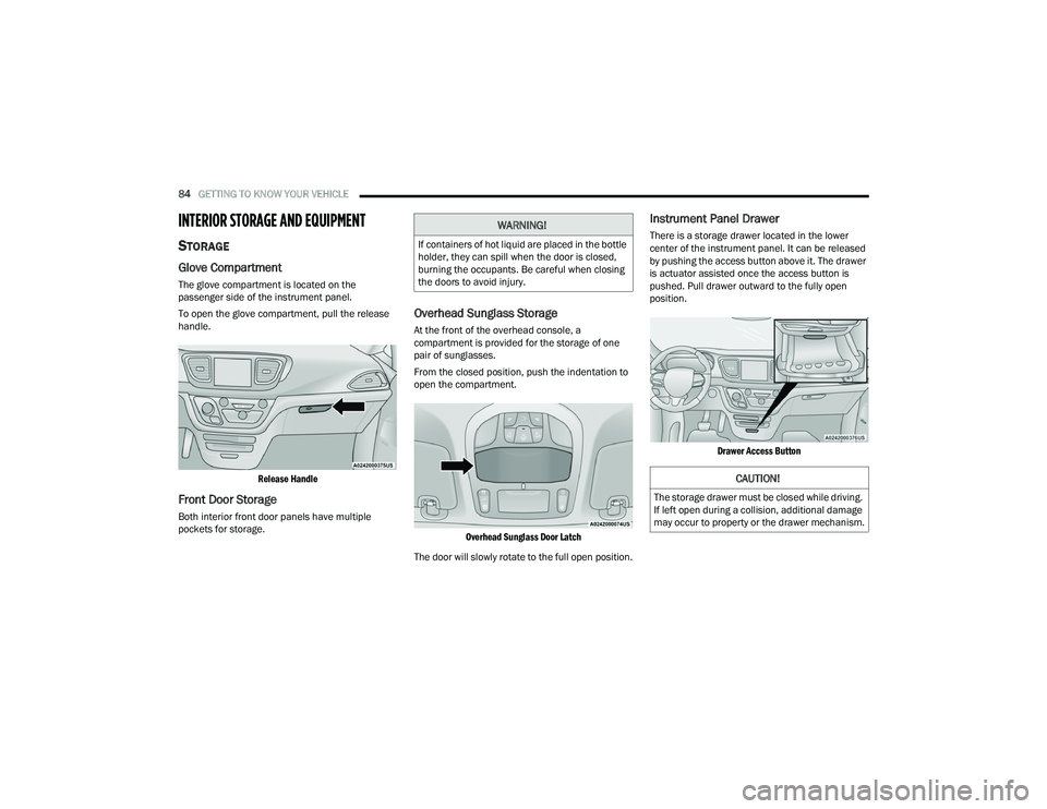
Instrument Panel Drawer
There is a storage drawer located in the lower
center of the instrument panel. It can be released
by pushing the access button above it. The drawer
is actuator assisted once the access button is
pushed. Pull drawer outward to the fully open
position.
Drawer Access Button
WARNING!
If containers of hot liquid are placed in the bottle
holder, they can spill when the door is closed,
burning the occupants. Be careful when closing
the doors to avoid injury.
CAUTION!
The storage drawer must be closed while driving.
If left open during a collision, additional damage
may occur to property or the drawer mechanism.
22_RUP_OM_EN_USC_t.book Page 84
Page 90 of 384

88GETTING TO KNOW YOUR VEHICLE
There are multiple USB “Charge Only” ports in this
vehicle.
In the center console
On the instrument panel
On the back of the front row seats in the Ucon -
nect Theater Media Hubs (if equipped)
On the back of the front row seats
Above the rear cup holder in the third row of
seats
Charge Only USB In The Center Console
NOTE:The USB outlet in the bottom of the instrument
panel can be switched from ignition only to
constant battery powered all the time. See an
authorized dealer for details.
Rear Seat USB Charging Port Without Uconnect Theater
Rear Seat USB Media Hub With Uconnect Theater 3rd Row USB Charging Port
NOTE:The USB “Charge Only” ports will recharge battery
operated USB devices when connected.
Different scenarios are listed below when a
non-phone device is plugged into the smaller and
larger USB ports, and when a phone device is
plugged into the smaller and larger USB ports:
“A new device is now connected. Previous
connection was lost”.
“(Phone Name) now connected. Previous
connection was lost”.
“Another device is in use through the same USB
port. Please disconnect the first device to use
the second device”.1 — Headphone Jack (Headphone Output Only)
2 — HDMI Port
3 — USB Port (Charge Only)
22_RUP_OM_EN_USC_t.book Page 88
Page 91 of 384

GETTING TO KNOW YOUR VEHICLE89
Plugging in a phone or another USB device may
cause the connection to a previous device to be
lost.
NOTE:Charge unsupported devices with the Charge Only
USB ports. If an unsupported device is plugged into
a Media USB port, a message will display on the
touchscreen that the device is not supported by
the system.
POWER OUTLETS
Your vehicle is equipped with 12 Volt (15 Amp)
power outlets, and 5 Volt (2.5 Amp) USB ports, that
can be used to power cellular phones, small
electronics and other low powered electrical
accessories. The power outlets can be labeled with
either a “key” or a “battery” symbol to indicate how
the outlet is powered. Power outlets labeled with a
key symbol are powered when the ignition is in the
ACC or ON/RUN position, while the outlets labeled
with a battery symbol are connected directly to the
battery and powered at all times.
NOTE:All accessories connected to the battery powered
outlets should be removed or turned off when the
vehicle is not in use to protect the battery against
discharge. Depending on the type of center console your
vehicle is equipped with, there is a front power
outlet located either on the center stack, bottom of
the instrument panel, or inside the center console.
12 Volt Front Power Outlet (On Center Stack) - If Equipped
12 Volt Front Power Outlet (In Floor Tray) - If Equipped
12 Volt Front Power Outlet (In Center Console)
CAUTION!
Power outlets are designed for accessory plugs
only. Do not insert any other object in the power
outlets as this will damage the outlet and blow
the fuse. Improper use of the power outlet can
cause damage not covered by your New Vehicle
Limited Warranty.
2
22_RUP_OM_EN_USC_t.book Page 89
Page 142 of 384

140STARTING AND OPERATING
IGNITION PARK INTERLOCK
This vehicle is equipped with an Ignition Park
Interlock which requires the transmission to be in
PARK before the ignition can be turned to the
OFF position. This helps the driver avoid
inadvertently leaving the vehicle without placing
the transmission in PARK. This system also locks
the transmission in PARK whenever the ignition is
in the OFF position.
NOTE:The transmission is NOT locked in PARK when the
ignition is in the ACC position (even though the
engine will be off). Ensure that the transmission is
in PARK, and the ignition is OFF (not in ACC
position) before exiting the vehicle.
BRAKE/TRANSMISSION SHIFT
I
NTERLOCK (BTSI) SYSTEM
This vehicle is equipped with a BTSI that holds the
transmission gear selector in PARK unless the
brakes are applied. To shift the transmission out of
PARK, the engine must be running and the brake
pedal must be pressed. The brake pedal must also
be pressed to shift from NEUTRAL into DRIVE or
REVERSE when the vehicle is stopped or moving at
low speeds.
9-SPEED AUTOMATIC TRANSMISSION
The transmission is controlled using a rotary
electronic gear selector located on the center
console. The transmission gear selector has PARK,
REVERSE, NEUTRAL, DRIVE, and LOW shift
positions. Using the LOW position manually
downshifts the transmission to a lower gear based
on vehicle speed. The transmission gear range
(PRNDL) is displayed both above the gear selector
and in the instrument cluster. To select a gear
range, simply rotate the gear selector. Push down
on the gear selector and then rotate it, to access
the L position. You must also press the brake pedal
to shift the transmission out of PARK (or NEUTRAL,
when stopped or moving at low speeds). To shift
past multiple gear ranges at once (such as PARK to
DRIVE), simply rotate the gear selector to the
appropriate detent. Select the DRIVE range for
normal driving.
NOTE:In the event of a mismatch between the gear
selector position and the actual transmission gear
(for example, driver selects PARK while driving),
the position indicator will blink continuously until
the selector is returned to the proper position, or
the requested shift can be completed.
The electronically controlled transmission adapts
its shift schedule based on driver inputs, along
with environmental and road conditions. The
transmission electronics are self-calibrating; therefore, the first few shifts on a new vehicle may
be somewhat abrupt. This is a normal condition,
and precision shifts will develop within a few
hundred miles (kilometers).
The 9-speed transmission has been developed to
meet the needs of current and future FWD/AWD
vehicles. Software and calibration is refined to
optimize the customer’s driving experience and
fuel economy. By design, some vehicle and
driveline combinations utilize NINTH gear only in
very specific driving situations and conditions.
Only shift from DRIVE to PARK or REVERSE when
the accelerator pedal is released and the vehicle is
stopped. Be sure to keep your foot on the brake
pedal when shifting between these gears.
Transmission Gear Selector
22_RUP_OM_EN_USC_t.book Page 140
Page 257 of 384

SAFETY255
(Continued)
The front passenger carries or holds an object
while seated (e.g., backpack, box, etc.).
Objects are lodged under the front passenger
seat.
Objects are lodged between the front passenger
seat and center console.
Accessories that may change the seated weight
on the front passenger seat are attached to the
front passenger seat.
Anything that may decrease or increase the
front passenger’s seated weight.
The OCS determines the front passenger’s most
probable classification. If an occupant in the front
passenger seat is seated improperly, the occupant
may provide an output signal to the OCS that is
different from the occupant’s properly seated
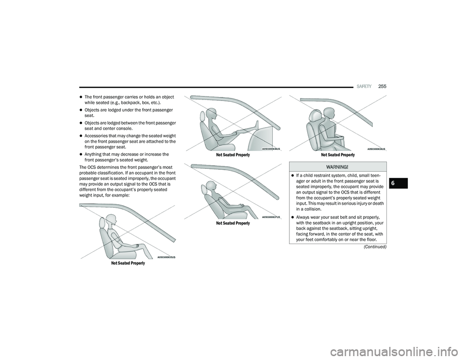
weight input, for example:
Not Seated Properly Not Seated Properly
Not Seated Properly
Not Seated Properly
WARNING!
If a child restraint system, child, small teen
-
ager or adult in the front passenger seat is
seated improperly, the occupant may provide
an output signal to the OCS that is different
from the occupant’s properly seated weight
input. This may result in serious injury or death
in a collision.
Always wear your seat belt and sit properly,
with the seatback in an upright position, your
back against the seatback, sitting upright,
facing forward, in the center of the seat, with
your feet comfortably on or near the floor.
6
22_RUP_OM_EN_USC_t.book Page 255
Page 336 of 384

334SERVICING AND MAINTENANCE
F68 ––Not Populated
F69 ––Not Populated
F70 ––Not Populated
F71 –20 Amp Yellow Horn
F72 –10 Amp Red Heated Mirror *
F73 30 Amp Pink –Rear Defroster
F74 20 Amp Blue –Trailer Tow Backup Lights*
F75 –5 Amp TanOverhead Console / RR Center Stack
F76 –20 Amp Yellow Uconnect / Center Display /
Telematics
F77 –10 Amp RedRR Entertainment / Media HUB /
USB(S) / Rain Sensor / Sunroof / RR View Mirror/ Overhead DVD Player / INT Monitoring Camera / Wireless Charging Pad
F78 –15 Amp BlueTCM (ZF) / E-Shifter / Cluster
F79 –10 Amp RedICS / HVAC / SCCM/ EPB SW
F80 ––Not Populated
F81 ––Not Populated
F82 ––Not Populated
CavityCartridge Fuse Blade FuseDescription
*If Equipped
22_RUP_OM_EN_USC_t.book Page 334