2022 CHRYSLER PACIFICA battery location
[x] Cancel search: battery locationPage 6 of 384

4
GETTING TO KNOW YOUR
INSTRUMENT PANEL
INSTRUMENT CLUSTER....................................... 110
Instrument Cluster Descriptions .................. 112
INSTRUMENT CLUSTER DISPLAY ..................... 112
Instrument Cluster Display Location And
Controls .......................................................... 113
Engine Oil Life ................................................ 114
KeySense Cluster Messages —
If Equipped..................................................... 115
Instrument Cluster Display Menu Items ..... 116
Battery Saver On/Battery Saver Mode
Message — Electrical Load Reduction
Actions — If Equipped.................................... 119
TRIP COMPUTER ................................................. 121
WARNING LIGHTS AND MESSAGES ................. 121
Red Warning Lights ....................................... 121
Yellow Warning Lights ................................... 124Yellow Indicator Lights .................................. 127
Green Indicator Lights................................... 127White Indicator Lights ................................... 128Blue Indicator Lights ..................................... 129 ONBOARD DIAGNOSTIC SYSTEM —
OBD II .................................................................... 129
Onboard Diagnostic System
(OBD II) Cybersecurity ................................... 129
EMISSIONS INSPECTION AND
MAINTENANCE PROGRAMS ............................. 130
STARTING AND OPERATING
STARTING THE ENGINE ...................................... 131
Normal Starting ............................................ 131
AutoPark ........................................................ 132Cold Weather Operation
(Below –22°F Or −30°C) ............................ 134
After Starting — Warming Up The Engine..... 134
If Engine Fails To Start ................................. 134
To Turn Off The Engine Using ENGINE
START/STOP Button ...................................... 135
ENGINE BLOCK HEATER — IF EQUIPPED ........ 135
ENGINE BREAK-IN RECOMMENDATIONS ....... 135
PARKING BRAKE ................................................. 136
Electric Park Brake (EPB) ............................ 136 AUTOMATIC TRANSMISSION ............................. 139
Ignition Park Interlock................................... 140
Brake/Transmission Shift Interlock (BTSI)
System ........................................................... 140
9-Speed Automatic Transmission ................ 140Gear Ranges .................................................. 141
ALL-WHEEL DRIVE (AWD) — IF EQUIPPED ...... 143
ACTIVE NOISE CANCELLATION .......................... 143
POWER STEERING............................................... 143
STOP/START SYSTEM — IF EQUIPPED ............. 143 Autostop Mode .............................................. 144
Possible Reasons The Engine Does Not
Autostop......................................................... 144
To Start The Engine While In Autostop ........ 145To Manually Turn Off The Stop/Start
System ........................................................... 145
To Manually Turn On The Stop/Start
System ........................................................... 145
System Malfunction ...................................... 145
CRUISE CONTROL SYSTEMS —
IF EQUIPPED ......................................................... 146
Cruise Control................................................ 146
Adaptive Cruise Control (ACC) ...................... 147
22_RUP_OM_EN_USC_t.book Page 4
Page 92 of 384

90GETTING TO KNOW YOUR VEHICLE
(Continued)
In addition to the front power outlet, there is also a
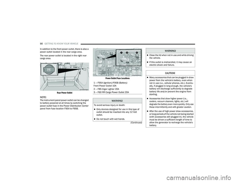
power outlet located in the rear cargo area.
The rear power outlet is located in the right rear
cargo area.
Rear Power Outlet
NOTE:The instrument panel power outlet can be changed
to battery powered at all times by switching the
power outlet fuse in the Power Distribution Center
panel from fuse location F95A to F95B.
Power Outlet Fuse Locations
1 — F95A (Ignition)/F95B (Battery)
Front Power Outlet 10A
2 — F85 Cigar Lighter 20A
3 — F60 RR Cargo Power Outlet 20A
WARNING!
To avoid serious injury or death:
Only devices designed for use in this type of
outlet should be inserted into any 12 Volt
outlet.
Do not touch with wet hands.
Close the lid when not in use and while driving
the vehicle.
If this outlet is mishandled, it may cause an
electric shock and failure.
CAUTION!
Many accessories that can be plugged in draw
power from the vehicle's battery, even when
not in use (i.e., cellular phones, etc.). Eventu
-
ally, if plugged in long enough, the vehicle's
battery will discharge sufficiently to degrade
battery life and/or prevent the engine from
starting.
Accessories that draw higher power (i.e.,
coolers, vacuum cleaners, lights, etc.) will
degrade the battery even more quickly. Only use
these intermittently and with greater caution.
After the use of high power draw accessories,
or long periods of the vehicle not being started
(with accessories still plugged in), the vehicle
must be driven a sufficient length of time to
allow the generator to recharge the vehicle's
battery.
WARNING!
22_RUP_OM_EN_USC_t.book Page 90
Page 104 of 384

102GETTING TO KNOW YOUR VEHICLE
The vacuum will operate in two modes:
Ignition in the ACC position: Engine remains off,
and vacuum usage is limited to 10 minutes.
Ignition in the START position: Engine is running,
and vacuum usage is unlimited until the
vehicle’s battery level falls below 60%.
NOTE:The vacuum will not operate when the ignition is in
the OFF position, or in the ON/RUN position with
the engine off. For more information on ignition
positions, see Ú page 18.
1. Before Using Vacuum:
Accessory (ACC) Mode Operation - For up to
10 minutes of operation
Always apply the parking brake, shift the trans -
mission into PARK, and push ignition button to
place ignition in Accessory (ACC) mode. The
engine will not be running in this mode. Do not
leave the key fob in or near the vehicle, or in a
location accessible to children.
NOTE:The vacuum system will run for 10 minutes off
battery power and then the vacuum will shut down.
A low battery indication light (LOW PWR) located
below the vacuum nozzle storage location will
come on one minute before the vacuum shuts
down. Engine Running (START) Operation - For more
than 10 minutes of operation
Position vehicle outdoors and fully open all
side windows.
Always apply the parking brake, shift the
transmission into PARK, and leave engine
running.
2. Unclip the vacuum nozzle and pull to extend
vacuum hose from the storage location.
NOTE:The hose can reach every corner of the vehicle
floor.
3. Install desired attachment if needed.
Front Storage Compartments
WARNING!
Carbon monoxide (CO) in exhaust gases can
cause serious injury or death. Follow these
precautions to prevent carbon monoxide
poisoning:
Do not inhale exhaust gases.
Do not start or run an engine in a closed
garage or confined area. Always position
vehicle outdoors and fully open all side
windows before using vacuum system with the
engine running.
Guard against carbon monoxide with proper
maintenance. Have the exhaust system
inspected every time the vehicle is raised.
Have any abnormal conditions repaired
promptly.
1 — Vacuum Nozzle Storage Location
2 — Attachment Compartment
22_RUP_OM_EN_USC_t.book Page 102
Page 286 of 384

284IN CASE OF EMERGENCY
(Continued)
NOTE:
Your vehicle may be transmitting data as
authorized by the subscriber.
Once a connection is made between the
vehicle’s SOS Call system and the SOS oper-
ator, the SOS operator may be able to open
a voice connection with the vehicle to deter -
mine if additional assistance is needed.
Once the SOS operator opens a voice
connection with the vehicle’s SOS Call
system, the operator should be able to
speak with you or other vehicle occupants
and hear sounds occurring in the vehicle.
The vehicle’s SOS Call system will attempt
to remain connected with the SOS operator
until the SOS operator terminates the
connection.
5. The SOS operator may attempt to contact appropriate emergency responders and
provide them with important vehicle
information and GPS coordinates.
WARNING!
If anyone in the vehicle could be in danger
(e.g., fire or smoke is visible, dangerous road
conditions or location), do not wait for voice
contact from an Emergency Services Agent. All
occupants should exit the vehicle immediately
and move to a safe location.
Never place anything on or near the vehicle’s
operable network and GPS antennas. You
could prevent operable network and GPS
signal reception, which can prevent your
vehicle from placing an emergency call. An
operable network and GPS signal reception is
required for the SOS Call system to function
properly.
The SOS Call system is embedded into the
vehicle’s electrical system. Do not add after -
market electrical equipment to the vehicle’s
electrical system. This may prevent your
vehicle from sending a signal to initiate an
emergency call. To avoid interference that can
cause the SOS Call system to fail, never add
aftermarket equipment (e.g., two-way mobile
radio, CB radio, data recorder, etc.) to your
vehicle’s electrical system or modify the
antennas on your vehicle. IF YOUR VEHICLE
LOSES BATTERY POWER FOR ANY REASON
(INCLUDING DURING OR AFTER AN ACCI -
DENT), THE UCONNECT FEATURES, APPS AND
SERVICES, AMONG OTHERS, WILL NOT
OPERATE.
Modifications to any part of the SOS Call
system could cause the air bag system to fail
when you need it. You could be injured if the
air bag system is not there to help protect you.
WARNING!
22_RUP_OM_EN_USC_t.book Page 284
Page 303 of 384

IN CASE OF EMERGENCY301
PREPARATIONS FOR JUMP START
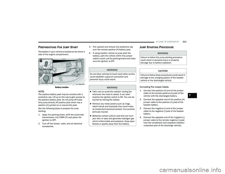
The battery in your vehicle is located on the driver’s
side of the engine compartment.
Battery Location
NOTE:The positive battery post may be covered with a
protective cap. Lift up on the cap to gain access to
the positive battery post. Do not jump off fuses.
Only jump directly off positive post which has a
positive (+) symbol on or around the post.
See the following steps to prepare for jump
starting:
1. Apply the parking brake, shift the automatic transmission into PARK (P) and place the
ignition to OFF.
2. Turn off the heater, radio, and all electrical accessories. 3. Pull upward and remove the protective cap
over the remote positive (+) battery post.
4. If using another vehicle to jump start the battery, park the vehicle within the jumper
cable’s reach, set the parking brake and make
sure the ignition is OFF.
JUMP STARTING PROCEDURE
Connecting The Jumper Cables
1. Connect the positive
(+) end of the jumper
cable to the remote positive (+)
post of the
vehicle with the discharged battery.
2. Connect the opposite end of the positive (+)
jumper cable to the positive (+) post of the
booster battery.
3. Connect the negative (-) end of the jumper
cable to the negative (-) post of the booster
battery.
4. Connect the opposite end of the negative (-)
jumper cable to the remote negative (-) post
near the windshield cowl (exposed metallic/
unpainted post of the discharge vehicle).
WARNING!
Do not allow vehicles to touch each other as this
could establish a ground connection and
personal injury could result.
WARNING!
Take care to avoid the radiator cooling fan
whenever the hood is raised. It can start
anytime the ignition switch is ON. You can be
injured by moving fan blades.
Remove any metal jewelry such as rings,
watch bands and bracelets that could make
an inadvertent electrical contact. You could be
seriously injured.
Batteries contain sulfuric acid that can burn
your skin or eyes and generate hydrogen gas
which is flammable and explosive. Keep open
flames or sparks away from the battery.
WARNING!
Failure to follow this jump starting procedure
could result in personal injury or property
damage due to battery explosion.
CAUTION!
Failure to follow these procedures could result in
damage to the charging system of the booster
vehicle or the discharged vehicle.
7
22_RUP_OM_EN_USC_t.book Page 301
Page 304 of 384

302IN CASE OF EMERGENCY
5. Start the engine in the vehicle that has the booster battery, let the engine idle a few
minutes, and then start the engine in the
vehicle with the discharged battery.
6. Once the engine is started, see the following disconnecting procedure for the next steps.
Disconnecting The Jumper Cables
1. Disconnect the negative
(-)
end of the jumper
cable from the remote negative post of the
vehicle with the discharged battery.
2. Disconnect the opposite end of the negative (-)
jumper cable from the negative (-) post of the
booster battery.
3. Disconnect the positive (+) end of the jumper
cable from the positive (+) post of the booster
battery.
4. Disconnect the opposite end of the positive (+)
jumper cable from the remote positive (+) post
of the vehicle with the discharged battery and
reinstall the protective cap. If frequent jump starting is required to start your
vehicle you should have the battery and charging
system inspected at an authorized dealer.
REFUELING IN EMERGENCY – IF EQUIPPED
The vehicle is equipped with a refueling funnel for
a Cap-Less Fuel System. If refueling is necessary,
while using an approved gas can, insert the
refueling funnel into the filler neck opening. Take
care to open both flappers with the funnel to avoid
spills.
NOTE:In certain cold conditions, ice may prevent the fuel
door from opening. If this occurs, lightly push on
the fuel door to break the ice buildup and
re-release the fuel door by pushing at the rear
center edge to unlatch.
Refueling Funnel
Emergency Gas Can Refueling
Most gas cans will not open the flapper doors. A
funnel is provided to allow emergency refueling
with a gas can.
See the following steps for refueling:
1. Retrieve funnel from the rear storage area.
Fuel Funnel Location
WARNING!
Do not connect the jumper cable to the negative
(-) post of the discharged battery. The resulting
electrical spark could cause the battery to
explode and could result in personal injury.
CAUTION!
Accessories plugged into the vehicle power
outlets draw power from the vehicle’s battery,
even when not in use (i.e., cellular devices, etc.).
Eventually, if plugged in long enough without
engine operation, the vehicle’s battery will
discharge sufficiently to degrade battery life
and/or prevent the engine from starting.
22_RUP_OM_EN_USC_t.book Page 302
Page 309 of 384

IN CASE OF EMERGENCY307
Vehicle Recovery Tow Points
Your vehicle is equipped with Vehicle Recovery
Points that can be used to recover a disabled
vehicle, located on the underbody of the vehicle.
NOTE:
Ensure that the towing service tow hooks are
properly seated and secured in the attachment
points.
This recovery tow feature should be used by a
trained professional only.
Use approved receptacle location to free the
disabled vehicle from its environment.
Front Recovery Points
If you must use the accessories (wipers,
defrosters, etc.) while being towed, the ignition
must be in the ON/RUN mode, not the ACC mode.
NOTE:The Safehold feature will engage the Electric Park
Brake whenever the driver's door is opened (if the
ignition is ON, transmission is not in PARK, and
brake pedal is released). If you are towing this
vehicle with the ignition in the ON/RUN mode, you
must manually disable the Electric Park Brake
each time the driver's door is opened, by pressing
the brake pedal and then releasing the EPB.
If the key fob is unavailable or the vehicle's battery
is discharged, detailed instructions on shifting the
transmission out of PARK in order to move the
vehicle Ú
page 304.
CAUTION!
Recovery feature:
Is to be used by a professional ONLY.
Is used only to provide recovery of the vehicle.
Is NOT to be used to recover secondary
vehicle.
Is NOT to be used for transporting the vehicle
over the road, i.e. “Flat Towing”.
Is to be used by a professional ONLY.
Is used only to provide recovery of the vehicle.
Is NOT to be used to recover secondary
vehicle.
Is NOT to be used for transporting the vehicle
over the road, i.e. “Flat Towing”.
Recovery load should:
Be applied at constant speed.
Be applied parallel to the center line of the
length of the vehicle.
Not be an abrupt acceleration.
Be applied at constant speed.
Be applied parallel to the center line of the
length of the vehicle.
Not be an abrupt acceleration.
CAUTION!
Do not use sling-type equipment when towing.
Vehicle damage may occur.
When securing the vehicle to a flatbed truck,
do not attach to front or rear suspension
components. Damage to your vehicle may
result from improper towing.
Ensure that the Electric Park Brake is
released, and remains released, while being
towed.
7
22_RUP_OM_EN_USC_t.book Page 307
Page 332 of 384

330SERVICING AND MAINTENANCE
Power Distribution Center Location
Cavity Cartridge Fuse Blade FuseDescription
*If Equipped
F06 ––Not Populated
F07 –25 Amp ClearIgnition Coil / Fuel Injector
F08 ––Not Populated
F09 –25 Amp ClearAmplifier / Active Noise Control *
F10 ––Not Populated
F11 ––Not Populated
F12 –5 Amp TanBattery Sensor (IBS)
F13 –10 Amp Red ECM (S) *
F14 –10 Amp Red ECM
22_RUP_OM_EN_USC_t.book Page 330