2022 CHRYSLER PACIFICA HYBRID tow
[x] Cancel search: towPage 106 of 384

104GETTING TO KNOW YOUR VEHICLE
5. When finished, push power button to turn vacuum off and store vacuum hose and any
attachments. 6. Before exiting the vehicle:
If the ignition is in the ACC position, push
the START/STOP ignition button to place
ignition in the OFF position, remove key fob
from the vehicle, and lock the vehicle.
If the engine is running, raise all of the
windows, push the START/STOP ignition
button to place ignition in the OFF position,
remove key fob from the vehicle, close all of
the doors and the liftgate and lock the
vehicle.
Vacuum Troubleshooting
DO NOT use with any opening blocked. If an
object becomes lodged in the hose, attempt to
fully extend the hose in a straight line while the
vacuum motor is running. If this does not
dislodge the object, turn the vacuum OFF and
remove the hose from the vehicle using the
subsequent removal instructions. If the filter is
clogged, follow the emptying debris bin proce -
dure and lightly tap the filter on the collection
bin to remove any collected debris from the
filter. Both the bin and the filter can be rinsed
with water if needed. To avoid mold and stale
odors, allow both to dry completely before rein -
stalling in your vehicle. If the filter has tears,
holes or other damage and needs to be
replaced, please contact an authorized dealer.
If there are any other issues with your vacuum,
contact an authorized dealer. Your vacuum has
no user serviceable parts.
Debris Bin
The debris bin is located behind the access panel
behind the third row seat on the driver’s side.
To Empty
1. Push power button to turn vacuum OFF.
2. Open the access panel by pulling the finger grip towards you and then pull downward.
Vacuum System Access Panel
Do not vacuum toxic material such as chlorine
bleach, ammonia, drain cleaner, etc.
Do not vacuum hard or sharp objects such as
glass, nails, screws, coins, etc.
Keep hair, loose clothing, fingers, and all parts
of body away from openings and moving parts.
Only use with filter in place. Periodically check
that the filter is in place and in good condition.
WARNING!
This equipment incorporates parts such as
switches, motors, or the like that tend to
produce arcs or sparks that can cause an
explosion. When using your vacuum near
gasoline-dispensing equipment or service
stations, park vehicle at least 20 ft (6 m) away
from the exterior enclosure of any dispensing
pump. The vacuum is mounted more than
18 inches (45 cm) above ground level in your
vehicle.
WARNING!
22_RUP_OM_EN_USC_t.book Page 104
Page 107 of 384

GETTING TO KNOW YOUR VEHICLE105
3. Twist the release knob counterclockwise and pull the bin towards you.
Debris Bin Release Knob
4. Remove the filter and dump the debris in a trash can. Lightly tap the filter on the collection
bin to remove loose debris from the filter. If the
filter is clogged from extended use, have the
filter replaced by an authorized dealer.
5. Reverse the procedure to reinstall.
NOTE:The debris bin must be fully installed and locked
for the vacuum to function properly. Hose Access Port
The hose access port is located behind the access
panel behind the third row seat on the driver’s
side.
To Remove Vacuum Hose For Cleaning
1. Open the access panel.
Vacuum System Access Panel
2. Open the small access panel on the upper right side, and unclip the hose from the hose
access port by pushing the yellow vacuum
hose release lever with right thumb and lifting
the hose with index finger.
Vacuum Hose Release Lever
3. Return to vacuum nozzle storage location located behind the sliding door.
4. Grab the vacuum nozzle and gently pull the hose out through vacuum nozzle storage
location.
5. Shake the hose to remove any objects stuck in the hose. Take care not to perforate the hose
while attempting to dislodge any objects.
6. Reverse the procedure to reinstall and clip the hose into place.
2
22_RUP_OM_EN_USC_t.book Page 105
Page 108 of 384

106GETTING TO KNOW YOUR VEHICLE
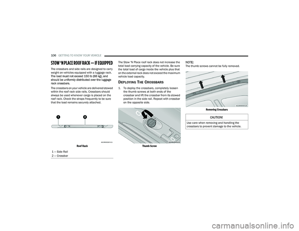
STOW ‘N PLACE ROOF RACK — IF EQUIPPED
The crossbars and side rails are designed to carry
weight on vehicles equipped with a luggage rack.
The load must not exceed 150 lb (68 kg), and
should be uniformly distributed over the luggage
rack crossbars.
The crossbars on your vehicle are delivered stowed
within the roof rack side rails. Crossbars should
always be used whenever cargo is placed on the
roof rack. Check the straps frequently to be sure
that the load remains securely attached.
Roof Rack
The Stow ‘N Place roof rack does not increase the
total load carrying capacity of the vehicle. Be sure
the total load of cargo inside the vehicle plus that
on the external rack does not exceed the maximum
vehicle load capacity.
DEPLOYING THE CROSSBARS
1. To deploy the crossbars, completely loosen
the thumb screws at both ends of the
crossbar and lift the crossbar from its stowed
position in the side rail. Repeat with crossbar
on the opposite side.
Thumb Screw
NOTE:The thumb screws cannot be fully removed.
Removing Crossbars
1 — Side Rail
2 — Crossbar
CAUTION!
Use care when removing and handling the
crossbars to prevent damage to the vehicle.
22_RUP_OM_EN_USC_t.book Page 106
Page 110 of 384

108GETTING TO KNOW YOUR VEHICLE
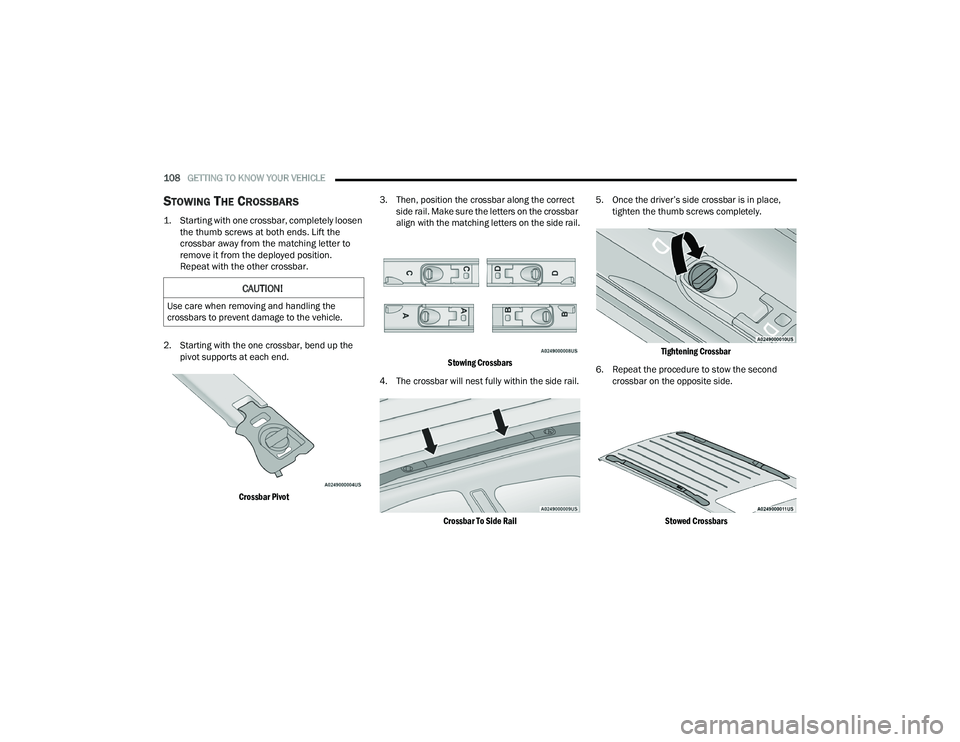
STOWING THE CROSSBARS
1. Starting with one crossbar, completely loosen
the thumb screws at both ends. Lift the
crossbar away from the matching letter to
remove it from the deployed position.
Repeat with the other crossbar.
2. Starting with the one crossbar, bend up the pivot supports at each end.
Crossbar Pivot
3. Then, position the crossbar along the correct
side rail. Make sure the letters on the crossbar
align with the matching letters on the side rail.
Stowing Crossbars
4. The crossbar will nest fully within the side rail.
Crossbar To Side Rail
5. Once the driver’s side crossbar is in place,
tighten the thumb screws completely.
Tightening Crossbar
6. Repeat the procedure to stow the second crossbar on the opposite side.
Stowed Crossbars
CAUTION!
Use care when removing and handling the
crossbars to prevent damage to the vehicle.
22_RUP_OM_EN_USC_t.book Page 108
Page 111 of 384

GETTING TO KNOW YOUR VEHICLE109
(Continued)
NOTE:
To help control wind noise, stow the crossbars in
the side rails when they are not in use.
If any metallic object is placed over the satellite
radio antenna (if equipped), you may experience
interruption of satellite radio reception.
WARNING!
Cargo must be securely tied down before driving
your vehicle. Improperly secured loads can fly off
the vehicle, particularly at high speeds, resulting
in personal injury or property damage. Follow
the roof rack cautions when carrying cargo on
your roof rack.
CAUTION!
To prevent damage to the roof of your vehicle,
DO NOT carry any loads on the roof rack
without the crossbars deployed. The load
should be secured and placed on top of the
crossbars, not directly on the roof. If it is
necessary to place the load on the roof, place
a blanket or other protective layer between
the load and the roof surface.
To avoid damage to the roof rack and vehicle,
do not exceed the maximum roof rack load
capacity of 150 lb (68 kg). Always distribute
heavy loads as evenly as possible and secure
the load appropriately.
Load should always be secured to cross bars
first, with tie down loops used as additional
securing points if needed. Tie loops are
intended as supplementary tie down points
only. Do not use ratcheting mechanisms with
the tie loops. Check the straps and thumb
wheels frequently to be sure that the load
remains securely attached.
Long loads that extend over the windshield,
such as wood panels or surfboards, or loads
with large frontal area should be secured to
both the front and rear of the vehicle.
Travel at reduced speeds and turn corners
carefully when carrying large or heavy loads
on the roof rack. Wind forces, due to natural
causes or nearby truck traffic, can add sudden
upward lift to a load. This is especially true on
large flat loads and may result in damage to
the cargo or your vehicle.
CAUTION!
2
22_RUP_OM_EN_USC_t.book Page 109
Page 122 of 384

120GETTING TO KNOW YOUR INSTRUMENT PANEL
NOTE:
The charging system is independent from load
reduction. The charging system performs a diag-
nostic on the charging system continuously.
If the Battery Charge Warning Light is on it may
indicate a problem with the charging system
Ú page 121.
The electrical loads that may be switched off (if
equipped), and vehicle functions which can be
effected by load reduction:
Heated Seat/Vented Seats/Heated Wheel
Heated/Cooled Cup Holders — If Equipped
Rear Defroster And Heated Mirrors
HVAC System
115 Volts AC Power Inverter System
Audio and Telematics System
Loss of the battery charge may indicate one or
more of the following conditions:
The charging system cannot deliver enough
electrical power to the vehicle system because
the electrical loads are larger than the capability
of charging system. The charging system is still
functioning properly.
Turning on all possible vehicle electrical loads
(e.g. HVAC to max settings, exterior and interior
lights, overloaded power outlets +12 Volts,
150W, USB ports) during certain driving condi -
tions (city driving, towing, frequent stopping).
Installing options like additional lights, upfitter
electrical accessories, audio systems, alarms
and similar devices.
Unusual driving cycles (short trips separated by
long parking periods).
The vehicle was parked for an extended period
of time (weeks, months).
The battery was recently replaced and was not
charged completely.
The battery was discharged by an electrical load
left on when the vehicle was parked.
The battery was used for an extended period
with the engine not running to supply radio,
lights, chargers, +12 Volt portable appliances
like vacuum cleaners, game consoles and
similar devices. What to do when an electrical load reduction
action message is present (“Battery Saver On” or
“Battery Saver Mode”)
During a trip:
Reduce power to unnecessary loads if possible:
Turn off redundant lights (interior or exterior)
Check what may be plugged in to power
outlets +12 Volts, 150W, USB ports
Check HVAC settings (blower, temperature)
Check the audio settings (volume)
After a trip:
Check if any aftermarket equipment was
installed (additional lights, upfitter electrical
accessories, audio systems, alarms) and review
specifications if any (load and Ignition Off Draw
currents).
Evaluate the latest driving cycles (distance,
driving time and parking time).
The vehicle should have service performed if
the message is still present during consecutive
trips and the evaluation of the vehicle and
driving pattern did not help to identify the cause.
22_RUP_OM_EN_USC_t.book Page 120
Page 125 of 384

GETTING TO KNOW YOUR INSTRUMENT PANEL123
Electronic Throttle Control (ETC) Warning
Light
This warning light will illuminate to
indicate a problem with the ETC system.
If a problem is detected while the vehicle
is running, the light will either stay on or
flash depending on the nature of the problem.
Cycle the ignition when the vehicle is safely and
completely stopped and the transmission is placed
in the PARK (P) position. The light should turn off.
If the light remains on with the vehicle running,
your vehicle will usually be drivable; however, see
an authorized dealer for service as soon as
possible.
NOTE:This light may turn on if the accelerator and brake
pedals are pressed at the same time.
If the light continues to flash when the vehicle is
running, immediate service is required and you
may experience reduced performance, an
elevated/rough idle, or engine stall and your
vehicle may require towing. The light will come on
when the ignition is placed in the ON/RUN or ACC/
ON/RUN position and remain on briefly as a bulb
check. If the light does not come on during starting,
have the system checked by an authorized dealer.
Engine Coolant Temperature Warning
Light
This warning light warns of an
overheated engine condition. If the
engine coolant temperature is too high,
this indicator will illuminate and a single
chime will sound. If the temperature reaches the
upper limit, a continuous chime will sound for
four minutes or until the engine is able to cool;
whichever comes first.
If the light turns on while driving, safely pull over
and stop the vehicle. If the Air Conditioning (A/C)
system is on, turn it off. Also, shift the transmission
into NEUTRAL (N) and idle the vehicle. If the
temperature reading does not return to normal,
turn the engine off immediately and call for service
Ú page 303.
Hood Open Warning Light
This warning light will illuminate when the
hood is left open and not fully closed.
NOTE:If the vehicle is moving, there will also be a single
chime.
Liftgate Open Warning Light
This warning light will illuminate when the
liftgate is open.
NOTE:If the vehicle is moving, there will also be a single
chime.
Oil Pressure Warning Light
This warning light will illuminate to
indicate low engine oil pressure. If the
light turns on while driving, stop the
vehicle, shut off the engine as soon as
possible, and contact an authorized dealer.
A chime will sound when this light turns on.
Do not operate the vehicle until the cause is
corrected. This light does not indicate how much oil
is in the engine. The engine oil level must be
checked under the hood.
Oil Temperature Warning Light
This warning light will illuminate to
indicate the engine oil temperature is
high. If the light turns on while driving,
stop the vehicle and shut off the engine
as soon as possible. Wait for oil temperature to
return to normal levels.
3
22_RUP_OM_EN_USC_t.book Page 123
Page 126 of 384

124GETTING TO KNOW YOUR INSTRUMENT PANEL
Seat Belt Reminder Warning Light
This warning light indicates when the
driver or passenger seat belt is
unbuckled. When the ignition is first
placed in the ON/RUN or ACC/ON/RUN
position and if the driver’s seat belt is unbuckled,
a chime will sound and the light will turn on. When
driving, if the driver or front passenger seat belt
remains unbuckled, the Seat Belt Reminder Light
will flash or remain on continuously and a chime
will sound Ú page 239.
Transmission Temperature Warning
Light — If Equipped
This warning light will illuminate to warn
of a high transmission fluid temperature.
This may occur with strenuous usage
such as trailer towing. If this light turns
on, stop the vehicle and run the engine at idle or
slightly faster, with the transmission in PARK (P) or
NEUTRAL (N), until the light turns off. Once the light
turns off, you may continue to drive normally.
Vehicle Security Warning Light —
If Equipped
This warning light will flash at a fast rate
for approximately 15 seconds when the
vehicle security system is arming, and
then will flash slowly until the vehicle is
disarmed.
YELLOW WARNING LIGHTS
Adaptive Cruise Control (ACC) Fault
Warning Light — If Equipped
This warning light will illuminate to
indicate a fault in the ACC system.
Contact a local authorized dealer for
service Ú page 147.
Electronic Park Brake Warning Light
This warning light will illuminate to
indicate the Electronic Park Brake is not
functioning properly and service is
required. Contact an authorized dealer.
Anti-Lock Brake System (ABS) Warning
Light
This warning light monitors the ABS.
The light will turn on when the ignition is
placed in the ON/RUN or ACC/ON/RUN
position and may stay on for as long as
four seconds.
If the ABS light remains on or turns on while
driving, then the Anti-Lock portion of the brake
system is not functioning and service is required as
soon as possible. However, the conventional brake
system will continue to operate normally,
assuming the Brake Warning Light is not also on.
WARNING!
If you continue operating the vehicle when the
Transmission Temperature Warning Light is
illuminated you could cause the fluid to boil over,
come in contact with hot engine or exhaust
components and cause a fire.
CAUTION!
Continuous driving with the Transmission
Temperature Warning Light illuminated will
eventually cause severe transmission damage
or transmission failure.
22_RUP_OM_EN_USC_t.book Page 124