2022 CHRYSLER PACIFICA HYBRID tow
[x] Cancel search: towPage 51 of 384

GETTING TO KNOW YOUR VEHICLE49
(Continued)
When enabled within Uconnect Settings, Easy
Entry and Easy Exit positions are stored in each
memory setting profile (if equipped) Ú
page 32.
NOTE:The Easy Entry/Exit feature is enabled or disabled
within the Uconnect system Úpage 188.
POWER ADJUSTMENT (REAR SEATS) —
I
F EQUIPPED
Third Row Power Recline — If Equipped
The power recline feature, located on the trim
panel next to the seat, adjusts the seatback angle
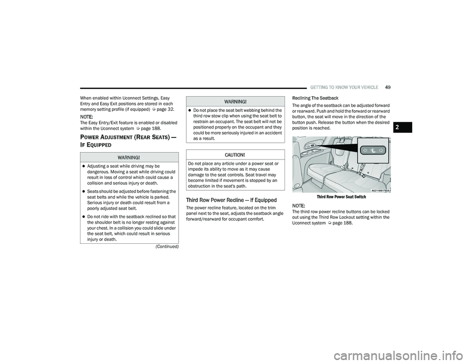
forward/rearward for occupant comfort. Reclining The Seatback
The angle of the seatback can be adjusted forward
or rearward. Push and hold the forward or rearward
button, the seat will move in the direction of the
button push. Release the button when the desired
position is reached.
Third Row Power Seat Switch
NOTE:The third row power recline buttons can be locked
out using the Third Row Lockout setting within the
Uconnect system Ú page 188.
WARNING!
Adjusting a seat while driving may be
dangerous. Moving a seat while driving could
result in loss of control which could cause a
collision and serious injury or death.
Seats should be adjusted before fastening the
seat belts and while the vehicle is parked.
Serious injury or death could result from a
poorly adjusted seat belt.
Do not ride with the seatback reclined so that
the shoulder belt is no longer resting against
your chest. In a collision you could slide under
the seat belt, which could result in serious
injury or death.
Do not place the seat belt webbing behind the
third row stow clip when using the seat belt to
restrain an occupant. The seat belt will not be
positioned properly on the occupant and they
could be more seriously injured in an accident
as a result.
CAUTION!
Do not place any article under a power seat or
impede its ability to move as it may cause
damage to the seat controls. Seat travel may
become limited if movement is stopped by an
obstruction in the seat's path.
WARNING!
2
22_RUP_OM_EN_USC_t.book Page 49
Page 52 of 384

50GETTING TO KNOW YOUR VEHICLE
Third Row Power Stow ‘n Go Seat —
If Equipped
A one-touch power folding seat switch is located in
the right rear trim panel as part of a switch bank.
NOTE:The third row outboard seat belts may interfere
with the power folding of the seat. Place the seat
belt webbing behind the stow clip before stowing or
opening the seat. When the seat is in the desired
position, remove the webbing from the stow clip so
that it is ready for use. Never leave the seat belt in
the stow clip when it is used to restrain an
occupant.
NOTE:
The outer head restraints will lower automati -
cally as necessary when the power seat begins
to move.
The center head restraint raises and lowers
manually but will not lower automatically.
The head restraint can also be lowered manu -
ally using the pull strap located at the back of
the seat Ú page 55.
The switch is only functional when the liftgate is
open and the vehicle is in PARK.
The rear switch bank allows multiple power folding
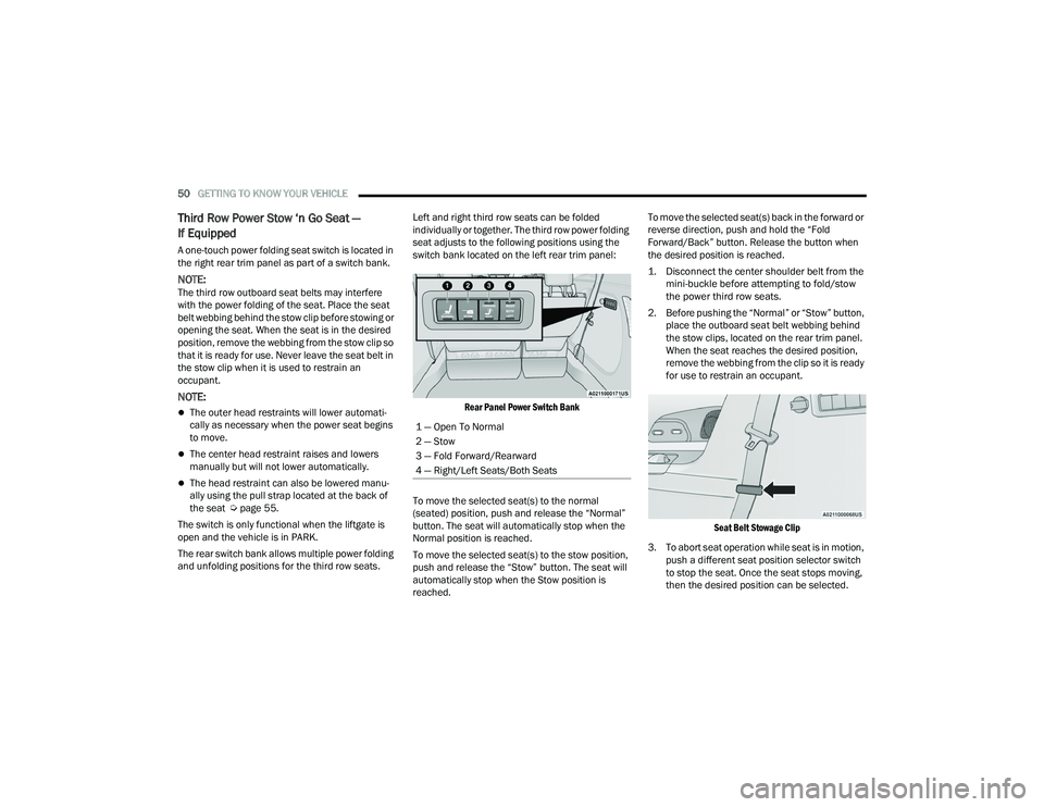
and unfolding positions for the third row seats. Left and right third row seats can be folded
individually or together. The third row power folding
seat adjusts to the following positions using the
switch bank located on the left rear trim panel:
Rear Panel Power Switch Bank
To move the selected seat(s) to the normal
(seated) position, push and release the “Normal”
button. The seat will automatically stop when the
Normal position is reached.
To move the selected seat(s) to the stow position,
push and release the “Stow” button. The seat will
automatically stop when the Stow position is
reached. To move the selected seat(s) back in the forward or
reverse direction, push and hold the “Fold
Forward/Back” button. Release the button when
the desired position is reached.
1. Disconnect the center shoulder belt from the
mini-buckle before attempting to fold/stow
the power third row seats.
2. Before pushing the “Normal” or “Stow” button, place the outboard seat belt webbing behind
the stow clips, located on the rear trim panel.
When the seat reaches the desired position,
remove the webbing from the clip so it is ready
for use to restrain an occupant.
Seat Belt Stowage Clip
3. To abort seat operation while seat is in motion, push a different seat position selector switch
to stop the seat. Once the seat stops moving,
then the desired position can be selected.
1 — Open To Normal
2 — Stow
3 — Fold Forward/Rearward
4 — Right/Left Seats/Both Seats
22_RUP_OM_EN_USC_t.book Page 50
Page 55 of 384

GETTING TO KNOW YOUR VEHICLE53
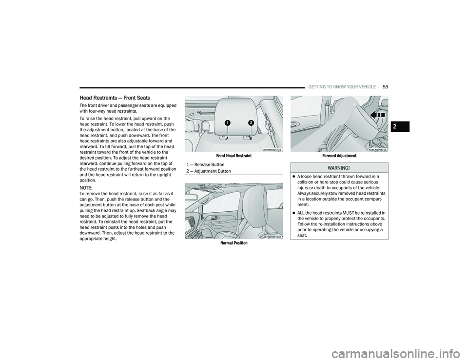
Head Restraints — Front Seats
The front driver and passenger seats are equipped
with four-way head restraints.
To raise the head restraint, pull upward on the
head restraint. To lower the head restraint, push
the adjustment button, located at the base of the
head restraint, and push downward. The front
head restraints are also adjustable forward and
rearward. To tilt forward, pull the top of the head
restraint toward the front of the vehicle to the
desired position. To adjust the head restraint
rearward, continue pulling forward on the top of
the head restraint to the furthest forward position
and the head restraint will return to the upright
position.
NOTE:To remove the head restraint, raise it as far as it
can go. Then, push the release button and the
adjustment button at the base of each post while
pulling the head restraint up. Seatback angle may
need to be adjusted to fully remove the head
restraint. To reinstall the head restraint, put the
head restraint posts into the holes and push
downward. Then, adjust the head restraint to the
appropriate height.
Front Head Restraint
Normal Position Forward Adjustment
1 — Release Button
2 — Adjustment Button
WARNING!
A loose head restraint thrown forward in a
collision or hard stop could cause serious
injury or death to occupants of the vehicle.
Always securely stow removed head restraints
in a location outside the occupant compart -
ment.
ALL the head restraints MUST be reinstalled in
the vehicle to properly protect the occupants.
Follow the re-installation instructions above
prior to operating the vehicle or occupying a
seat.
2
22_RUP_OM_EN_USC_t.book Page 53
Page 56 of 384

54GETTING TO KNOW YOUR VEHICLE
Head Restraints — Second Row Quad
Seats
The second row outboard head restraints, as well
as the removable 8th passenger seat (if equipped),
may have adjustable head restraints.
NOTE:If equipped with Stow ‘n Go seating, the head
restraints are non-adjustable and non-removable.
Do not pull on non-adjustable head restraints
when folding the seat.
To raise the head restraint, pull upward on the
head restraint. To lower the head restraint, push
the adjustment button, located at the base of the
head restraint, and push downward.
To remove the head restraint, raise it as far as it
can go. Then, push the release button and the
adjustment button at the base of each post while
pulling the head restraint up. Seatback angle may
need to be adjusted to fully remove the head
restraint. To reinstall the head restraint, put the
head restraint posts into the holes and push
downward. Then, adjust the head restraint to the
appropriate height.
Head Restraints — Second Row Bench
The second row bench seat is equipped with
adjustable head restraints.
To raise the head restraint, pull upward on the
head restraint. To lower the head restraint, push
the adjustment button, located at the base of the
head restraint, and push downward.
Bench Seat Head Restraint
To remove the head restraint, raise it as far as it
can go. Then, push the release button and the
adjustment button at the base of each post while
pulling the head restraint up. Seatback angle may
need to be adjusted to fully remove the head
restraint. To reinstall the head restraint, put the
head restraint posts into the holes and push
downward. Then, adjust the head restraint to the
appropriate height.
NOTE:For information on child restraint tethering, see
Ú
page 239.
1 — Release Button
2 — Adjustment Button
WARNING!
A loose head restraint thrown forward in a
collision or hard stop could cause serious
injury or death to occupants of the vehicle.
Always securely stow removed head restraints
in a location outside the occupant compart
-
ment.
ALL the head restraints MUST be reinstalled in
the vehicle to properly protect the occupants.
Follow the re-installation instructions above
prior to operating the vehicle or occupying a
seat.
22_RUP_OM_EN_USC_t.book Page 54
Page 59 of 384

GETTING TO KNOW YOUR VEHICLE57
ADDITIONAL INFORMATION
© 2021 FCA US LLC. All rights reserved. Mopar and
Uconnect are registered trademarks and Mopar
Owner Connect is a trademark of FCA US LLC.
SiriusXM® and all related marks and logos are
trademarks of SiriusXM® Radio Inc. Ú page 370.
For Uconnect system support, call
1-877-855-8400 (24 hours a day 7 days a week)
or visit
DriveUconnect.com (US) or DriveUconnect.ca (Canada).
MIRRORS
INSIDE REARVIEW MIRROR
Manual Mirror — If Equipped
A single ball joint mirror is used to allow the driver
to adjust up, down and left, right. The mirror should
be adjusted to center on the view through the rear
window. Headlight glare can be reduced by moving the
small control under the mirror to the night position
(toward the rear of the vehicle). The mirror should
be adjusted while set in the day position (toward
the windshield).
Manual Rearview Mirror
Automatic Dimming Mirror — If Equipped
This mirror automatically adjusts for headlight
glare from vehicles behind you. You can turn the
feature on or off by pushing the button at the base
of the mirror. A light to the left of the button will
illuminate to indicate when the dimming feature is
activated. The sensor to the right of the button
does not illuminate.
NOTE:This feature is disabled when the vehicle is in
REVERSE. If your vehicle is not equipped with an
on/off button on the mirror, the mirror will default
to on and can be turned on/off through the touch -
screen.
Automatic Dimming Mirror On/Off Button
CAUTION!
To avoid damage to the mirror during cleaning,
never spray any cleaning solution directly onto
the mirror. Apply the solution onto a clean cloth
and wipe the mirror clean.
2
22_RUP_OM_EN_USC_t.book Page 57
Page 60 of 384

58GETTING TO KNOW YOUR VEHICLE
ILLUMINATED VANITY MIRRORS —
I
F EQUIPPED
To access an illuminated vanity mirror, flip down
one of the visors and lift the cover.
Illuminated Mirror
OUTSIDE MIRRORS
The outside mirror(s) can be adjusted to the center
of the adjacent lane of traffic to achieve the
optimal view.
DRIVER'S OUTSIDE AUTOMATIC
D
IMMING MIRROR — IF EQUIPPED
The driver’s outside mirror will automatically adjust
for glare from vehicles behind you. This feature is
controlled by the inside automatic dimming mirror
and will automatically adjust for headlight glare
when the inside mirror adjusts.
CONVERSATION MIRROR
Located in the overhead console there is a
conversation mirror to view all the passengers in
the vehicle. Push the panel to release the drop
down mirror. Raise the mirror and push to latch it
back in the stowed position.
Conversation Mirror
WARNING!
Vehicles and other objects seen in an outside
convex mirror will look smaller and farther away
than they really are. Relying too much on side
convex mirrors could cause you to collide with
another vehicle or other object. Use your inside
mirror when judging the size or distance of a
vehicle seen in a side convex mirror.
22_RUP_OM_EN_USC_t.book Page 58
Page 68 of 384

66GETTING TO KNOW YOUR VEHICLE
From the O (off) position, rotate the headlight switch
clockwise to the first detent for parking light and
instrument panel light operation. Rotate the
headlight switch to the second detent for headlight,
parking light and instrument panel operation.
NOTE:For vehicles sold in Canada, rotate the headlight
switch clockwise from the parking light and
instrument panel light position to the first detent to
turn on the headlights also. Rotate to the second
detent, AUTO position, to turn on automatic head -
lights, parking lights, and instrument panel lights.
DAYTIME RUNNING LIGHTS (DRLS) —
I
F EQUIPPED
The headlights or LED light bars on your vehicle will
illuminate when the engine is started. This
provides a constant lights on condition until the
ignition is placed in the OFF position. If the parking
brake is applied, the Daytime Running Lights
(DRLs) will turn off.
NOTE:
For vehicles sold in Canada, the Daytime
Running Lights will automatically deactivate
when the front fog lights are turned on.
If allowed by law in the country in which the
vehicle was purchased, the Daytime Running
Lights can be turned on and off using the Ucon -
nect system Ú page 188.
On some vehicles, the Daytime Running Lights
may deactivate, or reduce intensity, on one side
of the vehicle (when a turn signal is activated on
that side), or on both sides of the vehicle (when
the hazard warning lights are activated).
HIGH/LOW BEAM SWITCH
Push the multifunction lever toward the instrument
panel to switch the headlights to high beams.
Pulling the multifunction lever back will turn the
low beams on.
AUTOMATIC HIGH BEAM — IF EQUIPPED
The Automatic High Beam system provides
increased forward lighting at night by automatically
controlling the high beams through the use of a
camera mounted on the windshield. This camera
detects vehicle specific light and automatically
switches from high beams to low beams until the
approaching vehicle is out of view.
NOTE:Broken, muddy, or obstructed headlights and tail -
lights of vehicles in the field of view will cause
headlights to remain on longer (closer to the
vehicle). Also, dirt, film and other obstructions on
the windshield or camera lens will cause the
system to function improperly.
To Activate
1. Select “Auto Dim High Beams” through the Uconnect system to enable the feature
Ú
page 188.
2. Rotate the headlight switch clockwise to the AUTO position.
3. Push the multifunction lever away from you to switch the headlights to the high beam
position. Refer to “Multifunction Lever” in this
section for further information.
NOTE:This system will not activate until the vehicle is at,
or above 16 mph (25 km/h).
To Deactivate
Perform either of the following steps to deactivate
the Automatic High Beam system.
1. Deselect “Auto Dim High Beams” through the Uconnect system
Ú
page 188.
2. Pull the multifunction lever toward you to switch the headlights from the high beam to
the low beam position.
3. Rotate the headlight switch counterclockwise from the AUTO to the on position.
NOTE:Once active, the Automatic High Beam system will
stop functioning below 12 mph (20 km/h).
22_RUP_OM_EN_USC_t.book Page 66
Page 69 of 384

GETTING TO KNOW YOUR VEHICLE67
FLASH-TO-PASS
You can signal another vehicle with your headlights
by lightly pulling the multifunction lever toward you.
This will cause the high beam headlights to turn on,
and remain on, until the lever is released.
AUTOMATIC HEADLIGHTS — IF EQUIPPED
This system automatically turns your headlights on
or off based on ambient light levels. To turn the
system on, turn the headlight switch to the extreme
clockwise position aligning the indicator with the
AUTO on the headlight switch. When the system is
on, the Headlight Time Delay feature is also on.
This means your headlights will stay on for up to
90 seconds after the ignition is placed in the OFF
position. To turn the automatic system off, move
the headlight switch out of the AUTO position.
NOTE:The engine must be running before the headlights
will come on in the Automatic mode.
HEADLIGHTS ON WITH WIPERS —
I
F EQUIPPED
When your headlights are in the AUTO mode and
the engine is running, the headlights will
automatically turn on when the wiper system is
also turned on. Headlights on when windshield
wipers are on may be found on vehicles equipped
with an automatic headlight system.
NOTE:The Headlights with Wipers feature can be turned
on or off through the Uconnect system
Ú page 188.
HEADLIGHT TIME DELAY — IF EQUIPPED
This feature provides the safety of headlight
illumination for up to 90 seconds after exiting your
vehicle.
To activate the delay feature, place the ignition in
the OFF position while the headlights are still on.
The 90 second delay interval begins when
headlight switch is turned off. If the headlights or
parking lights are turned back on or the ignition is
placed in the ON position, the delay will be
cancelled. When exiting the vehicle the driver can choose to
have the headlights remain on for 30, 60, or
90 seconds or not remain on. You can change
the timer setting through the Uconnect system
Ú
page 188.
If the headlights are turned off before the ignition,
they will turn off in the normal manner.
NOTE:The headlights must be turned off within
45 seconds of placing the ignition in the OFF
position to activate this feature.
LIGHTS-ON REMINDER
If the headlights or the parking lights are left on
after the ignition is placed in the OFF position, the
vehicle will chime when the driver's door is opened.
2
22_RUP_OM_EN_USC_t.book Page 67