2022 CHRYSLER PACIFICA HYBRID tow bar
[x] Cancel search: tow barPage 108 of 384
106GETTING TO KNOW YOUR VEHICLE
STOW ‘N PLACE ROOF RACK — IF EQUIPPED
The crossbars and side rails are designed to carry
weight on vehicles equipped with a luggage rack.
The load must not exceed 150 lb (68 kg), and
should be uniformly distributed over the luggage
rack crossbars.
The crossbars on your vehicle are delivered stowed
within the roof rack side rails. Crossbars should
always be used whenever cargo is placed on the
roof rack. Check the straps frequently to be sure
that the load remains securely attached.
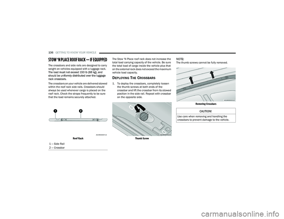
Roof Rack
The Stow ‘N Place roof rack does not increase the
total load carrying capacity of the vehicle. Be sure
the total load of cargo inside the vehicle plus that
on the external rack does not exceed the maximum
vehicle load capacity.
DEPLOYING THE CROSSBARS
1. To deploy the crossbars, completely loosen
the thumb screws at both ends of the
crossbar and lift the crossbar from its stowed
position in the side rail. Repeat with crossbar
on the opposite side.
Thumb Screw
NOTE:The thumb screws cannot be fully removed.
Removing Crossbars
1 — Side Rail
2 — Crossbar
CAUTION!
Use care when removing and handling the
crossbars to prevent damage to the vehicle.
22_RUP_OM_EN_USC_t.book Page 106
Page 110 of 384
108GETTING TO KNOW YOUR VEHICLE
STOWING THE CROSSBARS
1. Starting with one crossbar, completely loosen
the thumb screws at both ends. Lift the
crossbar away from the matching letter to
remove it from the deployed position.
Repeat with the other crossbar.
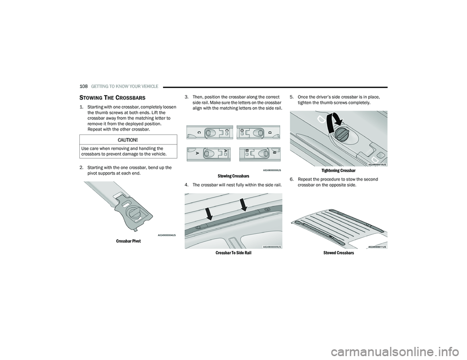
2. Starting with the one crossbar, bend up the pivot supports at each end.
Crossbar Pivot
3. Then, position the crossbar along the correct
side rail. Make sure the letters on the crossbar
align with the matching letters on the side rail.
Stowing Crossbars
4. The crossbar will nest fully within the side rail.
Crossbar To Side Rail
5. Once the driver’s side crossbar is in place,
tighten the thumb screws completely.
Tightening Crossbar
6. Repeat the procedure to stow the second crossbar on the opposite side.
Stowed Crossbars
CAUTION!
Use care when removing and handling the
crossbars to prevent damage to the vehicle.
22_RUP_OM_EN_USC_t.book Page 108
Page 111 of 384
GETTING TO KNOW YOUR VEHICLE109
(Continued)
NOTE:
To help control wind noise, stow the crossbars in
the side rails when they are not in use.
If any metallic object is placed over the satellite
radio antenna (if equipped), you may experience
interruption of satellite radio reception.
WARNING!
Cargo must be securely tied down before driving
your vehicle. Improperly secured loads can fly off
the vehicle, particularly at high speeds, resulting
in personal injury or property damage. Follow
the roof rack cautions when carrying cargo on
your roof rack.
CAUTION!
To prevent damage to the roof of your vehicle,
DO NOT carry any loads on the roof rack
without the crossbars deployed. The load
should be secured and placed on top of the
crossbars, not directly on the roof. If it is
necessary to place the load on the roof, place
a blanket or other protective layer between
the load and the roof surface.
To avoid damage to the roof rack and vehicle,
do not exceed the maximum roof rack load
capacity of 150 lb (68 kg). Always distribute
heavy loads as evenly as possible and secure
the load appropriately.
Load should always be secured to cross bars
first, with tie down loops used as additional
securing points if needed. Tie loops are
intended as supplementary tie down points
only. Do not use ratcheting mechanisms with
the tie loops. Check the straps and thumb
wheels frequently to be sure that the load
remains securely attached.
Long loads that extend over the windshield,
such as wood panels or surfboards, or loads
with large frontal area should be secured to
both the front and rear of the vehicle.
Travel at reduced speeds and turn corners
carefully when carrying large or heavy loads
on the roof rack. Wind forces, due to natural
causes or nearby truck traffic, can add sudden
upward lift to a load. This is especially true on
large flat loads and may result in damage to
the cargo or your vehicle.
CAUTION!
2
22_RUP_OM_EN_USC_t.book Page 109
Page 177 of 384

STARTING AND OPERATING175
Gross Axle Weight Rating (GAWR)
The GAWR is the maximum capacity of the front
and rear axles. Distribute the load over the front
and rear axles evenly. Make sure that you do not
exceed either front or rear GAWR Ú page 173.
Tongue Weight (TW)
The TW is the downward force exerted on the hitch
ball by the trailer. You must consider this as part of
the load on your vehicle.
Trailer Frontal Area
The Frontal Area is the maximum height multiplied
by the maximum width of the front of a trailer.
Trailer Sway Control (TSC)
The TSC can be a mechanical telescoping link that
can be installed between the hitch receiver and the
trailer tongue that typically provides adjustable
friction associated with the telescoping motion to
dampen any unwanted trailer swaying motions
while traveling.
The electronic TSC (if equipped), recognizes a
swaying trailer and automatically applies individual
wheel brakes and/or reduces engine power to
attempt to eliminate the trailer sway.
Weight-Carrying Hitch
A Weight-Carrying Hitch supports the trailer tongue
weight, just as if it were luggage located at a hitch
ball or some other connecting point of the vehicle.
These kinds of hitches are commonly used to tow
small and medium sized trailers.
Weight-Distributing Hitch
A weight-distributing hitch works by applying
leverage through spring (load) bars. They are
typically used for heavier loads to distribute trailer
tongue weight to the tow vehicle's front axle and
the trailer axle(s). When used in accordance with
the manufacturer’s directions, it provides for a
more level ride, offering more consistent steering
and brake control thereby enhancing towing safety. The addition of a friction/hydraulic sway
control also dampens sway caused by traffic and
crosswinds and contributes positively to tow
vehicle and trailer stability. TSC and a
weight-distributing (load equalizing) hitch are
recommended for heavier TW and may be required
depending on vehicle and trailer configuration/
loading to comply with GAWR requirements.
WARNING!
It is important that you do not exceed the
maximum front or rear GAWR. A dangerous
driving condition can result if either rating is
exceeded. You could lose control of the vehicle
and have a collision.
WARNING!
An improperly adjusted weight-distributing
hitch system may reduce handling, stability,
braking performance, and could result in a
collision.
Weight-distributing systems may not be
compatible with surge brake couplers. Consult
with your hitch and trailer manufacturer or a
reputable Recreational Vehicle dealer for
additional information.
4
22_RUP_OM_EN_USC_t.book Page 175
Page 271 of 384

SAFETY269
Car Seat With Head Restraint Folded
Locating The LATCH Anchorages
If applicable, refer to the “Hybrid Supplement” for
additional information. The lower anchorages are round bars
that are found at the rear of the seat
cushion where it meets the seatback,
below the anchorage symbols on the
seatback. They are just visible when you lean into
the rear seat to install the child restraint. You will
easily feel them if you run your finger along the gap
between the seatback and seat cushion.
LATCH Anchorages (Second Row Anchorages Shown) 7 Passenger Stow ‘n Go Seating LATCH Anchorages (Second Row Anchorages Shown)
8 Passenger Seating
LATCH Anchorages (Second Row Bench Anchorages Shown) 7 Passenger Bench Seating
WARNING!
Always make sure the head restraint is in its
upright position when the seat is to be used by
an occupant who is not in a child restraint.
Sitting in a seat with the head restraint in its
lowered position could result in serious injury or
death in a collision.
1 — Folded Headrest
2 — Child Restraint
6
22_RUP_OM_EN_USC_t.book Page 269
Page 272 of 384
270SAFETY
Locating The Upper Tether Anchorages
If applicable, refer to the “Hybrid Supplement” for
additional information.
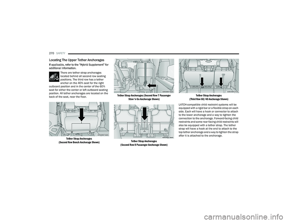
There are tether strap anchorages
located behind all second row seating
positions. The third row has a tether
anchor on the 40% seat for the right
outboard position and in the center of the 60%
seat for either the center or left outboard seating
position. All tether anchorages are located on the
back of the seat, near the floor.
Tether Strap Anchorages
(Second Row Bench Anchorage Shown) Tether Strap Anchorages (Second Row 7 Passenger
Stow ‘n Go Anchorage Shown)
Tether Strap Anchorages
(Second Row 8 Passenger Anchorage Shown) Tether Strap Anchorages
(Third Row 60/40 Anchorage Shown)
LATCH-compatible child restraint systems will be
equipped with a rigid bar or a flexible strap on each
side. Each will have a hook or connector to attach
to the lower anchorage and a way to tighten the
connection to the anchorage. Forward-facing child
restraints and some rear-facing child restraints will
also be equipped with a tether strap. The tether
strap will have a hook at the end to attach to the
top tether anchorage and a way to tighten the strap
after it is attached to the anchorage.
22_RUP_OM_EN_USC_t.book Page 270
Page 293 of 384

IN CASE OF EMERGENCY291
6. Install the inflatable spare on the vehicle, located in the rear cargo area of the vehicle.
Mounting Inflatable Spare Tire
NOTE:Do not install the wheel cover on the inflatable
spare tire.
7. Leave the vehicle on the jack and start inflating the inflatable spare after the tire has
been mounted to the vehicle. Secure the
wheel to the hub by tightening the nuts with
the wrench. After inflation, once the vehicle is
lowered you will have a second opportunity to
torque the lug nuts Ú page 360.
8. Inflate the tire to the prescribed pressure 60 psi (4.2 Bar) using the Portable Air
Compressor Ú page 293 or Tire Service Kit if
equipped Ú page 294.
9. Lower the vehicle once the inflatable Spare has reached its pressure and the
compressor-hose has been removed from the
tire valve. 10. Finish tightening the lug nuts. Push down on
the wrench while at the end of the handle for
increased leverage. Tighten the lug nuts in a
star pattern until each nut has been tightened
twice Ú page 360. If in doubt about the
correct tightness, have them checked with a
torque wrench by an authorized dealer or at a
service station.
11. Lower the jack to its fully-closed position.
12. Place the deflated (flat) tire and foam tray cover assembly in the rear cargo area. Do not
stow the deflated tire in the inflatable spare
tire location. Have the full-sized tire repaired or
replaced, as soon as possible.
WARNING!
To avoid the risk of forcing the vehicle off the
jack, do not tighten the wheel nuts fully until the
vehicle has been lowered. Failure to follow this
warning may result in serious injury.
CAUTION!
Be sure to mount the inflatable spare tire with
the valve stem facing outward. The vehicle could
be damaged if the inflatable spare tire is
mounted incorrectly.
WARNING!
A loose tire or jack thrown forward in a collision
or hard stop could endanger the occupants of
the vehicle. Always stow the jack parts and the
spare tire in the places provided. Have the
deflated (flat) tire repaired or replaced
immediately.
7
22_RUP_OM_EN_USC_t.book Page 291
Page 308 of 384
306IN CASE OF EMERGENCY
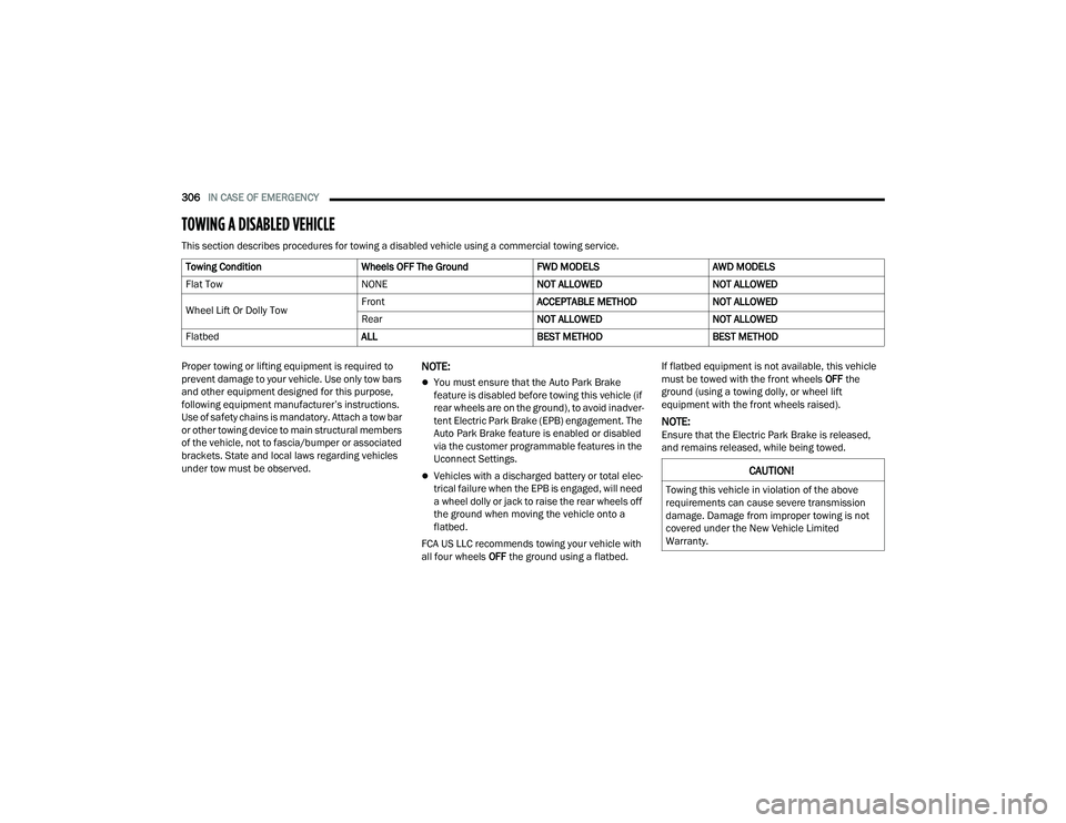
TOWING A DISABLED VEHICLE
This section describes procedures for towing a disabled vehicle using a commercial towing service.
Proper towing or lifting equipment is required to
prevent damage to your vehicle. Use only tow bars
and other equipment designed for this purpose,
following equipment manufacturer’s instructions.
Use of safety chains is mandatory. Attach a tow bar
or other towing device to main structural members
of the vehicle, not to fascia/bumper or associated
brackets. State and local laws regarding vehicles
under tow must be observed.
NOTE:
You must ensure that the Auto Park Brake
feature is disabled before towing this vehicle (if
rear wheels are on the ground), to avoid inadver -
tent Electric Park Brake (EPB) engagement. The
Auto Park Brake feature is enabled or disabled
via the customer programmable features in the
Uconnect Settings.
Vehicles with a discharged battery or total elec -
trical failure when the EPB is engaged, will need
a wheel dolly or jack to raise the rear wheels off
the ground when moving the vehicle onto a
flatbed.
FCA US LLC recommends towing your vehicle with
all four wheels OFF the ground using a flatbed. If flatbed equipment is not available, this vehicle
must be towed with the front wheels
OFF the
ground (using a towing dolly, or wheel lift
equipment with the front wheels raised).
NOTE:Ensure that the Electric Park Brake is released,
and remains released, while being towed.
Towing Condition
Wheels OFF The GroundFWD MODELSAWD MODELS
Flat Tow NONENOT ALLOWEDNOT ALLOWED
Wheel Lift Or Dolly Tow Front
ACCEPTABLE METHODNOT ALLOWED
Rear NOT ALLOWEDNOT ALLOWED
Flatbed ALLBEST METHODBEST METHOD
CAUTION!
Towing this vehicle in violation of the above
requirements can cause severe transmission
damage. Damage from improper towing is not
covered under the New Vehicle Limited
Warranty.
22_RUP_OM_EN_USC_t.book Page 306