2022 CHRYSLER PACIFICA HYBRID warning light
[x] Cancel search: warning lightPage 285 of 384

IN CASE OF EMERGENCY283
If equipped, the rearview mirror contains an SOS
and ASSIST button.
NOTE:
Your vehicle may be transmitting data as
authorized by the subscriber Ú page 370.
The SOS and ASSIST buttons will only function
if you are connected to an operable LTE
(voice/data) or 4G (data) network, which comes
as a built in function. Other Uconnect services
will only be operable if your SiriusXM Guardian™
service is active and you are connected to an
operable LTE (voice/data) or 4G (data) network. ASSIST Call
The ASSIST Button is used to automatically
connect you to any one of the following support
centers:
Roadside Assistance – If you get a flat tire, or
need a tow, just push the ASSIST button and you
will be connected to a representative for assis-
tance. Roadside Assistance will know what
vehicle is being driven and its location. Addi-
tional fees may apply for roadside assistance.
SiriusXM Guardian™ Customer Care – In-vehicle
support for SiriusXM Guardian™.
Vehicle Customer Care – Total support for all
other vehicle issues.
Uconnect Customer Care - Total support for
Radio, Phone and NAV issues.
SOS Call
1. Push the SOS Call button on the Rearview Mirror.
NOTE:In case the SOS Call button is pushed in error,
there will be a 10 second delay before the SOS Call
system initiates a call to a SOS operator. To cancel
the SOS Call connection, push the SOS call button
on the Rearview Mirror or press the cancellation
button on the Device Screen. Termination of the
SOS Call will turn off the green LED light on the
Rearview Mirror. 2. The LED light located between the SOS and
ASSIST buttons on the Rearview Mirror will
turn green once a connection to a SOS
operator has been made.
3. Once a connection between the vehicle and a SOS operator is made, the SOS Call system
may transmit the following important vehicle
information to a SOS operator:
Indication that the occupant placed a SOS
Call
The vehicle brand
The last known GPS coordinates of the
vehicle
4. You should be able to speak with the SOS operator through the vehicle audio system to
determine if additional assistance is needed.
WARNING!
ALWAYS obey traffic laws and pay attention to
the road. ALWAYS drive safely with your hands on
the steering wheel. You have full responsibility
and assume all risks related to the use of the
features and applications in this vehicle. Only
use the features and applications when it is safe
to do so. Failure to do so may result in an
accident involving serious injury or death.
7
22_RUP_OM_EN_USC_t.book Page 283
Page 287 of 384

IN CASE OF EMERGENCY285
(Continued)
SOS Call System Limitations
Vehicles sold in Mexico
DO NOT have SOS Call
system capabilities.
SOS or other emergency line operators in Mexico
may not answer or respond to SOS system calls.
If the SOS Call system detects a malfunction, any
of the following may occur at the time the
malfunction is detected, and at the beginning of
each ignition cycle:
The Rearview Mirror light located between the
SOS and ASSIST buttons will continuously be
illuminated red.
The Device Screen will display the following
message “Vehicle device requires service.
Please contact an authorized dealer.”
An In-Vehicle Audio message will state “Vehicle
device requires service. Please contact an
authorized dealer.” Even if the SOS Call system is fully functional,
factors beyond FCA US LLC’s control may prevent
or stop the SOS Call system operation. These
include, but are not limited to, the following
factors:
The ignition is in the OFF position
The vehicle’s electrical systems are not intact
The SOS Call system software and/or hardware
are damaged during a crash
The vehicle battery loses power or becomes
disconnected during a vehicle crash
LTE (voice/data) or 4G (data) network and/or
Global Positioning Satellite signals are unavail
-
able or obstructed
Equipment malfunction at the SOS operator
facility
Operator error by the SOS operator
LTE (voice/data) or 4G (data) network conges -
tion
Weather
Buildings, structures, geographic terrain, or
tunnels
WARNING!
Ignoring the Rearview Mirror light could mean
you will not have SOS Call services. If the Rear -
view Mirror light is illuminated, have an autho -
rized dealer service the SOS Call system
immediately.
The Occupant Restraint Control module turns
on the air bag Warning Light on the instrument
panel if a malfunction in any part of the
system is detected. If the Air Bag Warning
Light is illuminated, have an authorized dealer
service the Occupant Restraint Control system
immediately.
WARNING!
WARNING!
ALWAYS obey traffic laws and pay attention to
the road. ALWAYS drive safely with your hands on
the steering wheel. You have full responsibility
and assume all risks related to the use of the
features and applications in this vehicle. Only
use the features and applications when it is safe
to do so. Failure to do so may result in an
accident involving serious injury or death.
7
22_RUP_OM_EN_USC_t.book Page 285
Page 294 of 384

292IN CASE OF EMERGENCY
13. Stow the jack back in the stowage compartment and place the access panel
back. The stud of the storage area must be
threaded through the lower part of the jack.
Then turn the Jack Screw clockwise to secure
it in place.
NOTE:Stow the foam tray and components in the cargo
area.
Storing The Jack
ROAD TIRE INSTALLATION
Vehicles Equipped With Wheel Covers
1. Mount the road tire on the axle.
2. To ease the installation process for steel wheels with wheel covers, install two lug nuts
on the mounting studs which are on each side
of the valve stem. Install the lug nuts with the
cone shaped end of the nut toward the wheel.
Lightly tighten the lug nuts.
Tire And Wheel Cover Or Center Cap
3. Align the valve notch in the wheel cover with
the valve stem on the wheel. Install the cover
by hand, snapping the cover over the two lug
nuts. Do not use a hammer or excessive force
to install the cover.
4. Install the remaining lug nuts with the cone shaped end of the nut toward the wheel.
Lightly tighten all the lug nuts until the wheel
sits flush onto the hub and there is no play. The
nuts will have to be fully tightened once the
vehicle is lowered. Tightening an improperly
seated wheel under vehicle load can damage
the threads, cause vibration, and undermine
safety.
1 — Jack Screw
2 — Jack
3 — Stud
1 — Valve Stem
2 — Valve Notch
3 — Road Tire
4 — Wheel Cover
5 — Wheel Lug Nut
WARNING!
To avoid the risk of forcing the vehicle off the
jack, do not tighten the wheel nuts fully until the
vehicle has been lowered. Failure to follow this
warning may result in serious injury.
22_RUP_OM_EN_USC_t.book Page 292
Page 304 of 384

302IN CASE OF EMERGENCY
5. Start the engine in the vehicle that has the booster battery, let the engine idle a few
minutes, and then start the engine in the
vehicle with the discharged battery.
6. Once the engine is started, see the following disconnecting procedure for the next steps.
Disconnecting The Jumper Cables
1. Disconnect the negative
(-)
end of the jumper
cable from the remote negative post of the
vehicle with the discharged battery.
2. Disconnect the opposite end of the negative (-)
jumper cable from the negative (-) post of the
booster battery.
3. Disconnect the positive (+) end of the jumper
cable from the positive (+) post of the booster
battery.
4. Disconnect the opposite end of the positive (+)
jumper cable from the remote positive (+) post
of the vehicle with the discharged battery and
reinstall the protective cap. If frequent jump starting is required to start your
vehicle you should have the battery and charging
system inspected at an authorized dealer.
REFUELING IN EMERGENCY – IF EQUIPPED
The vehicle is equipped with a refueling funnel for
a Cap-Less Fuel System. If refueling is necessary,
while using an approved gas can, insert the
refueling funnel into the filler neck opening. Take
care to open both flappers with the funnel to avoid
spills.
NOTE:In certain cold conditions, ice may prevent the fuel
door from opening. If this occurs, lightly push on
the fuel door to break the ice buildup and
re-release the fuel door by pushing at the rear
center edge to unlatch.
Refueling Funnel
Emergency Gas Can Refueling
Most gas cans will not open the flapper doors. A
funnel is provided to allow emergency refueling
with a gas can.
See the following steps for refueling:
1. Retrieve funnel from the rear storage area.
Fuel Funnel Location
WARNING!
Do not connect the jumper cable to the negative
(-) post of the discharged battery. The resulting
electrical spark could cause the battery to
explode and could result in personal injury.
CAUTION!
Accessories plugged into the vehicle power
outlets draw power from the vehicle’s battery,
even when not in use (i.e., cellular devices, etc.).
Eventually, if plugged in long enough without
engine operation, the vehicle’s battery will
discharge sufficiently to degrade battery life
and/or prevent the engine from starting.
22_RUP_OM_EN_USC_t.book Page 302
Page 305 of 384

IN CASE OF EMERGENCY303
2. Insert funnel into same filler pipe opening as the fuel nozzle.
Inserting Funnel
3. Ensure funnel is inserted fully to hold flapper doors open.
4. Pour fuel into funnel opening.
5. Remove funnel from filler pipe, clean off prior to putting back in the spare tire storage area.
IF YOUR ENGINE OVERHEATS
If the vehicle is overheating, it will need to be
serviced by an authorized dealer.
In any of the following situations, you can reduce
the potential for overheating by taking the
appropriate action.
On the highway — slow down.
In city traffic — while stopped, place the trans -
mission in NEUTRAL (N), but do not increase
engine idle speed.
NOTE:There are steps that you can take to slow down an
impending overheat condition:
If your Air Conditioner (A/C) is on, turn it off. The
A/C system adds heat to the engine cooling
system and turning the A/C off can help remove
this heat.
You can also turn the temperature control to
maximum heat, the mode control to floor and
the blower control to high. This allows the heater
core to act as a supplement to the radiator and
aids in removing heat from the engine cooling
system.
CAUTION!
To avoid fuel spillage and overfilling, do not
“top off” the fuel tank after filling.
WARNING!
Never have any smoking materials lit in or
near the vehicle when the fuel door is open or
the tank is being filled.
Never add fuel when the engine is running.
This is in violation of most state and federal
fire regulations and may cause the Malfunc -
tion Indicator Light to turn on.
A fire may result if fuel is pumped into a
portable container that is inside of a vehicle.
You could be burned. Always place fuel
containers on the ground while filling.
WARNING!
You or others can be badly burned by hot engine
coolant (antifreeze) or steam from your radiator.
If you see or hear steam coming from under the
hood, do not open the hood until the radiator
has had time to cool. Never try to open a cooling
system pressure cap when the radiator or
coolant bottle is hot.
7
22_RUP_OM_EN_USC_t.book Page 303
Page 329 of 384

SERVICING AND MAINTENANCE327
(Continued)
Make sure that the coolant expansion bottle
overflow hoses are not kinked or obstructed.
Keep the front of the radiator clean. If your
vehicle is equipped with air conditioning, keep
the front of the condenser clean.
Do not change the thermostat for Summer or
Winter operation. If replacement is ever neces -
sary, install ONLY the correct type thermostat.
Other designs may result in unsatisfactory
engine cooling performance, poor gas mileage,
and increased emissions.
BRAKE SYSTEM
In order to ensure brake system performance, all
brake system components should be inspected
periodically. For the proper maintenance intervals
Ú page 310.
Brake Master Cylinder
The fluid in the master cylinder should be checked
when performing under hood services or
immediately if the Brake Warning Light is
illuminated.
Be sure to clean the top of the master cylinder area
before removing the cap. If necessary, add fluid to
bring the fluid level up to the requirements
described on the brake fluid reservoir. With disc
brakes, fluid level can be expected to fall as the
brake pads wear. Brake fluid level should be
checked when pads are replaced. However, low
fluid level may be caused by a leak and a checkup
may be needed.
Use only manufacturer recommended brake fluid
Úpage 366.
WARNING!
Riding the brakes can lead to brake failure and
possibly a collision. Driving with your foot resting
or riding on the brake pedal can result in
abnormally high brake temperatures, excessive
lining wear, and possible brake damage. You
would not have your full braking capacity in an
emergency.
WARNING!
Use only manufacturer recommended brake
fluid Ú page 366. Using the wrong type of
brake fluid can severely damage your brake
system and/or impair its performance. The
proper type of brake fluid for your vehicle is
also identified on the original factory installed
hydraulic master cylinder reservoir.
To avoid contamination from foreign matter or
moisture, use only new brake fluid or fluid that
has been in a tightly closed container. Keep
the master cylinder reservoir cap secured at
all times. Brake fluid in an open container
absorbs moisture from the air resulting in a
lower boiling point. This may cause it to boil
unexpectedly during hard or prolonged
braking, resulting in sudden brake failure. This
could result in a collision.
Overfilling the brake fluid reservoir can result
in spilling brake fluid on hot engine parts,
causing the brake fluid to catch fire. Brake
fluid can also damage painted and vinyl
surfaces, care should be taken to avoid its
contact with these surfaces.
Do not allow petroleum-based fluid to contam -
inate the brake fluid. Brake seal components
could be damaged, causing partial or
complete brake failure. This could result in a
collision.
WARNING!
8
22_RUP_OM_EN_USC_t.book Page 327
Page 351 of 384

SERVICING AND MAINTENANCE349
Life Of Tire
The service life of a tire is dependent upon varying
factors including, but not limited to:
Driving style.
Tire pressure - Improper cold tire inflation pres -
sures can cause uneven wear patterns to
develop across the tire tread. These abnormal
wear patterns will reduce tread life, resulting in
the need for earlier tire replacement.
Distance driven.
Performance tires, tires with a speed rating of V
or higher, and Summer tires typically have a
reduced tread life. Rotation of these tires per
the vehicle scheduled maintenance is highly
recommended.
NOTE:Wheel valve stem must be replaced as well when
installing new tires due to wear and tear in existing
tires. Keep dismounted tires in a cool, dry place with as
little exposure to light as possible. Protect tires
from contact with oil, grease, and gasoline.
Replacement Tires
The tires on your new vehicle provide a balance of
many characteristics. They should be inspected
regularly for wear and correct cold tire inflation
pressures. The manufacturer strongly
recommends that you use tires equivalent to the
originals in size, quality and performance when
replacement is needed Ú
page 348. The Load
Index and Speed Symbol for your tire will be found
on the original equipment tire sidewall.
See the Tire Sizing Chart example found in the Tire
Safety Information section of this manual for more
information relating to the Load Index and Speed
Symbol of a tire Ú page 340.
It is recommended to replace the two front tires or
two rear tires as a pair. Replacing just one tire can
seriously affect your vehicle’s handling. If you ever
replace a wheel, make sure that the wheel’s
specifications match those of the original wheels.
It is recommended you contact an authorized tire
dealer or original equipment dealer with any
questions you may have on tire specifications or
capability. Failure to use equivalent replacement
tires may adversely affect the safety, handling, and
ride of your vehicle.
WARNING!
Tires and the spare tire should be replaced after
six years, regardless of the remaining tread.
Failure to follow this warning can result in
sudden tire failure. You could lose control and
have a collision resulting in serious injury or
death.
WARNING!
Do not use a tire, wheel size, load rating, or
speed rating other than that specified for your
vehicle. Some combinations of unapproved
tires and wheels may change suspension
dimensions and performance characteristics,
resulting in changes to steering, handling, and
braking of your vehicle. This can cause unpre -
dictable handling and stress to steering and
suspension components. You could lose
control and have a collision resulting in
serious injury or death. Use only the tire and
wheel sizes with load ratings approved for
your vehicle.
Never use a tire with a smaller load index or
capacity, other than what was originally
equipped on your vehicle. Using a tire with a
smaller load index could result in tire over -
loading and failure. You could lose control and
have a collision.
Failure to equip your vehicle with tires having
adequate speed capability can result in
sudden tire failure and loss of vehicle control.
8
22_RUP_OM_EN_USC_t.book Page 349
Page 362 of 384

360
TECHNICAL SPECIFICATIONS
VEHICLE IDENTIFICATION NUMBER (VIN)
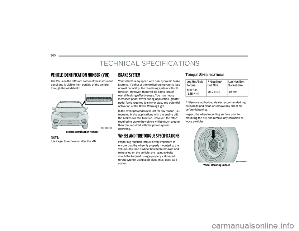
The VIN is on the left front corner of the instrument
panel and is visible from outside of the vehicle
through the windshield.
Vehicle Identification Number
NOTE:It is illegal to remove or alter the VIN.
BRAKE SYSTEM
Your vehicle is equipped with dual hydraulic brake
systems. If either of the two hydraulic systems lose
normal capability, the remaining system will still
function. However, there will be some loss of
overall braking effectiveness. You may notice
increased pedal travel during application, greater
pedal force required to slow or stop, and potential
activation of the Brake Warning Light.
In the event power assist is lost for any reason (i.e.,
repeated brake applications with the engine off)
the brakes will still function. However, the effort
required to brake the vehicle will be much greater
than that required with the power system
operating.
WHEEL AND TIRE TORQUE SPECIFICATIONS
Proper lug nut/bolt torque is very important to
ensure that the wheel is properly mounted to the
vehicle. Any time a wheel has been removed and
reinstalled on the vehicle, the lug nuts/bolts
should be torqued using a properly calibrated
torque wrench using a six-sided (hex) deep wall
socket.
TORQUE SPECIFICATIONS
**Use only authorized dealer recommended lug
nuts/bolts and clean or remove any dirt or oil
before tightening.
Inspect the wheel mounting surface prior to
mounting the tire and remove any corrosion or
loose particles.
Wheel Mounting Surface
Lug Nut/Bolt
Torque **Lug Nut/
Bolt SizeLug Nut/Bolt
Socket Size
100 ft-lb
(135 N·m) M12 x 1.5 19 mm
22_RUP_OM_EN_USC_t.book Page 360