2022 ALFA ROMEO GIULIA ABS
[x] Cancel search: ABSPage 154 of 248

SAFETY
152
Knee Impact Bolsters
The Knee Impact Bolsters help protect the knees
of the driver and front passenger, and position
the front occupants for improved interaction with
the front air bags.
Supplemental Driver And Front
Passenger Knee Air Bags
This vehicle is equipped with a Supplemental
Driver Knee Air Bag mounted in the instrument
panel below the steering column and a Supple-
mental Passenger Knee Air Bag mounted in the
instrument panel below the glove compartment.
The Supplemental Knee Air Bags provide
enhanced protection during a frontal impact by
working together with the seat belts, preten -
sioners, and front air bags.
Driver Knee Air Bag Front Passenger Knee Air Bag
Supplemental Side Air Bags
Supplemental Seat-Mounted Side Air Bags
(SABs)
This vehicle is equipped with Supplemental
Seat-Mounted Side Air Bags (SABs).
Supplemental Seat-Mounted Side Air Bags
(SABs) are located in the outboard side of the
front seats. The SABs are marked with a “SRS
AIRBAG” or “AIRBAG” on a label or on the seat
trim on the outboard side of the seats.
The SABs may help to reduce the risk of occupant
injury during certain side impacts, in addition to
the injury reduction potential provided by the seat
belts and body structure.
Front Supplemental Seat-Mounted Side Air Bag
When the SAB deploys, it opens the seam on the
outboard side of the seatback’s trim cover. The
inflating SAB deploys through the seat seam into
the space between the occupant and the door.
The SAB moves at a very high speed and with
such a high force that it could injure occupants if
they are not seated properly, or if items are
positioned in the area where the SAB inflates.
Children are at an even greater risk of injury from
a deploying air bag.
WARNING!
Do not drill, cut, or tamper with the knee
impact bolsters in any way.
Do not mount any accessories to the knee
impact bolsters such as alarm lights,
stereos, citizen band radios, etc.
WARNING!
Do not use accessory seat covers or place
objects between you and the Side Air Bags;
the performance could be adversely affected
and/or objects could be pushed into you,
causing serious injury.
22_GA_OM_EN_USC_t.book Page 152
Page 174 of 248

IN CASE OF EMERGENCY
172
(Continued)
(Continued)
The Tire Service Kit includes:
Sealant cartridge containing the sealing fluid.
Filler tube.
Adhesive label with the writing "Max. 50 mph
(80 km/h)”, to be attached in a position easily
visible to the driver (e.g. on the dashboard)
after repairing the tire.
Air compressor, complete with pressure gauge
and connectors.
An instruction pamphlet for reference in
prompt and correct use of the Tire Service Kit,
which must be then given to the personnel
dealing with the sealant-treated tire.
A pair of protective gloves.
Adaptors for inflating different elements.
Tire Service Kit Components
NOTE:
The sealant is effective with external tempera -
tures of between -40°F (-40°C) and 122°F
(50°C). The sealant has an expiration date.
To use the Tire Service Kit, proceed as follows:
1. Stop the vehicle in a position where you can repair the tire safely. You should be as far as
possible from the side of the road, and in a
position that is not dangerous for oncoming
traffic. Activate the Hazard Warning Flashers,
remove the safety triangle from the trunk,
and place it at a suitable distance from the
vehicle to make other drivers aware of your
presence.
2. Verify that the valve stem (on the wheel with the deflated tire) is in a position that is near
to the ground. This will allow the tire service
kit hoses to reach the valve stem and keep
the tire repair kit flat on the ground.
3. Place the gear selector to PARK (P).
4. Apply the Electric Park Brake and cycle the engine OFF.
INFLATION PROCEDURE
1 — Sealant Cartridge
2 — Filler Tube
3 — Adhesive Label
4 — Air Compressor
WARNING!
Do not attempt to seal a tire on the side of
the vehicle closest to traffic. Pull far enough
off the road to avoid the danger of being hit
when using the Tire Service Kit.
Do not use Tire Service Kit or drive the
vehicle under the following circumstances:
• If the puncture in the tire tread is approx-
imately 1/4 inch (6 mm) or larger.
•If the tire has any sidewall damage.
• If the tire has any damage from driving
with extremely low tire pressure.
• If the tire has any damage from driving
on a flat tire.
• If the wheel has any damage.
• If you are unsure of the condition of the
tire or the wheel.
Keep Tire Service Kit away from open flames
or heat sources.
A loose Tire Service Kit thrown forward in a
collision or hard stop could endanger the
occupants of the vehicle. Always stow the
Tire Service Kit in the place provided. Failure
to follow these warnings can result in injuries
that are serious or fatal to you, your
passengers, and others around you.
Take care not to allow the contents of Tire
Service Kit to come in contact with hair, eyes,
or clothing. Tire Service Kit sealant is harmful
if inhaled, swallowed, or absorbed through
the skin. It causes skin, eye, and respiratory
irritation. Flush immediately with plenty of
water if there is any contact with eyes or skin.
Change clothing as soon as possible, if there
is any contact with clothing.
WARNING!
22_GA_OM_EN_USC_t.book Page 172
Page 190 of 248
SERVICING AND MAINTENANCE
188
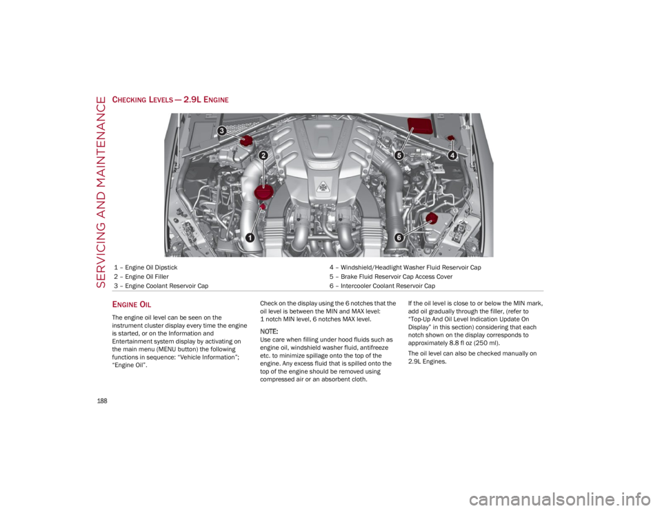
CHECKING LEVELS — 2.9L ENGINE
E
NGINE OIL
The engine oil level can be seen on the
instrument cluster display every time the engine
is started, or on the Information and
Entertainment system display by activating on
the main menu (MENU button) the following
functions in sequence: “Vehicle Information”;
“Engine Oil”. Check on the display using the 6 notches that the
oil level is between the MIN and MAX level:
1 notch MIN level, 6 notches MAX level.
NOTE:
Use care when filling under hood fluids such as
engine oil, windshield washer fluid, antifreeze
etc. to minimize spillage onto the top of the
engine. Any excess fluid that is spilled onto the
top of the engine should be removed using
compressed air or an absorbent cloth.If the oil level is close to or below the MIN mark,
add oil gradually through the filler, (refer to
“Top-Up And Oil Level Indication Update On
Display” in this section) considering that each
notch shown on the display corresponds to
approximately 8.8 fl oz (250 ml).
The oil level can also be checked manually on
2.9L Engines.
1 – Engine Oil Dipstick
4 – Windshield/Headlight Washer Fluid Reservoir Cap
2 – Engine Oil Filler 5 – Brake Fluid Reservoir Cap Access Cover
3 – Engine Coolant Reservoir Cap 6 – Intercooler Coolant Reservoir Cap
22_GA_OM_EN_USC_t.book Page 188
Page 192 of 248
SERVICING AND MAINTENANCE
190
(Continued)
ENGINE COOLANT
If the level is too low, remove the cap of reservoir
and add the fluid described on
Ú
page 233.
WASHER FLUID FOR WINDSHIELD/
H
EADLIGHTS
The windshield and headlights washer fluid
reservoir has a telescopic filler.
If the level is too low, remove reservoir cap and lift
the filler. Then, add the fluid described on
Ú
page 233.
NOTE:
Use care when filling under hood fluids such as
engine oil, windshield washer fluid, antifreeze
etc. to minimize spillage onto the top of the
engine. Any excess fluid that is spilled onto the
top of the engine should be removed using
compressed air or an absorbent cloth.
NOTE:
The headlight washing system will not work if the
liquid level is low (as indicated by the symbol on
the instrument cluster display). On vehicles
equipped with headlight washers, there is a refer -
ence notch on the dipstick: ONLY the windshield/
rear window washer operates with the level below
this reference.
BRAKE FLUID
Check that the fluid is at the maximum level. If
the fluid level in the tank is low, contact an
authorized dealer to have the system checked.
AUTOMATIC TRANSMISSION ACTIVATION
S
YSTEM OIL
The transmission control oil level should only be
checked at an authorized dealer.
USEFUL ADVICE FOR EXTENDING THE
L
IFE OF YOUR BATTERY
To avoid draining your battery and make it last
longer, observe the following instructions:
When you park the car, ensure that the doors
and trunk are closed properly to prevent any
lights from remaining on inside the
passenger's compartment.
Do not keep accessories (e.g. radio, hazard
warning lights, etc.) switched on for a long time
when the engine is not running.
Before performing any operation on the
electrical system, disconnect the negative
battery cable.
If you wish to install electrical accessories after
purchasing the car that require permanent
electrical supply (e.g. alarm, etc.), or accessories
which influence the electrical supply
requirements, contact an authorized dealer,
whose qualified staff will evaluate the overall
electrical consumption.
NOTE:
After the battery is disconnected, the steering
must be initialized. The warning light on the
instrument panel switches on to indicate this. To
carry out this procedure, simply turn the steering
wheel all the way from one end to the other, and
then turn it back to the central position.
BATTERY
The battery does not require the electrolyte to be
topped up with distilled water. A periodic check
carried out at an authorized dealer, however, is
necessary to check efficiency.
Follow the battery manufacturer's instructions for
maintenance.
Replacing The Battery
If necessary, replace the battery with another
original battery with the same specifications.
Follow the battery manufacturer’s instructions for
maintenance.
CAUTION!
If the charge level remains under 50% for a
long time, the battery may be damaged by
sulphation, reducing its capacity and
efficiency during a vehicle start. The battery is
also more prone to the risk of freezing (at
temperatures as high as 14°F (-10°C).
WARNING!
Battery acid is a corrosive solution and can
burn or even blind you. Do not allow battery
acid to contact your eyes, skin, or clothing.
Do not lean over a battery when attaching
clamps
Ú
page 177. If acid splashes in eyes
or on skin, flush the area immediately with
large amounts of water.
Battery gas is flammable and explosive.
Keep flame or sparks away from the battery.
Do not use a booster battery or any other
booster source with an output greater than
12 Volts. Do not allow cable clamps to touch
each other.
22_GA_OM_EN_USC_t.book Page 190
Page 197 of 248
195
(Continued)
ENGINE COOLING SYSTEM
Coolant Check
Your vehicle has two cooling systems and they
both need to be checked to ensure they are at
proper fill levels.
Check the engine coolant and intercooler coolant
level every oil change or before long trips.
If there are impurities in the engine coolant, the
system must be drained, flushed and refilled:
contact an authorized dealer.
Check the front part of the condenser for any
buildup of insects, leaves or other debris. Should
it be dirty, clean it by spraying delicately with
water.
Check the hoses of the engine/intercooler
cooling system to ensure that the rubber has not
deteriorated and that there are no cracks, tears,
cuts or obstructions in the expansion tank side
and radiator side connectors. Should there be
any doubt regarding leaks from the system (e.g. if
frequent top ups are required), have the seal
checked at an authorized dealer.
With the engine off and at normal operating
temperature, check that the cooling system
radiator cap is closed properly.
NOTE:
Before removing the coolant reservoir cap, wait
for the system to cool down.
Topping Up / Draining / Flushing The Engine/
Intercooler Coolant
If the engine coolant (antifreeze) is dirty, have
cleaning and flushing carried out at an authorized
dealer.
For the correct servicing intervals
Ú
page 182.
NOTE:
For topping up, use a fluid with the same
characteristics as those indicated on
Ú
page 233.
Do not use pure water, alcohol-based coolants,
corrosions inhibitors or additional anti-rust
products because they may be incompatible
with the engine coolant and cause the clogging
of the radiator. The use of propylene
glycol-based coolant is also not recommended.
Use care when filling under hood fluids such as
engine oil, windshield washer fluid, antifreeze
etc. to minimize spillage onto the top of the
engine. Any excess fluid that is spilled onto the
top of the engine should be removed using
compressed air or an absorbent cloth.
WARNING!
Exhaust gases can injure or kill. They contain
carbon monoxide (CO), which is colorless and
odorless. Breathing it can make you
unconscious and can eventually poison you.
A hot exhaust system can start a fire if you
park over materials that can burn. Such
materials might be grass or leaves coming
into contact with your exhaust system. Do not
park or operate your vehicle in areas where
your exhaust system can contact anything
that can burn.
WARNING!
You or others can be badly burned by hot
engine coolant (antifreeze) or steam from
your radiator. If you see or hear steam
coming from under the hood, do not open the
hood until the radiator has had time to cool.
Never open a cooling system pressure cap
when the radiator or coolant bottle is hot.
Keep hands, tools, clothing, and jewelry away
from the radiator cooling fan when the hood
is raised. The fan starts automatically and
may start at any time, whether the engine is
running or not.
When working near the radiator cooling fan,
disconnect the fan motor lead or turn the
ignition to the OFF position. The fan is
temperature controlled and can start at any
time the ignition is in the ON position.
WARNING!
Do not open hot engine cooling system.
Never add engine coolant (antifreeze) when
the engine is overheated. Do not loosen or
remove the cap to cool an overheated
engine. Heat causes pressure to build up in
the cooling system. To prevent scalding or
injury, do not remove the pressure cap while
the system is hot or under pressure.
Do not use a pressure cap other than the one
specified for your vehicle. Personal injury or
engine damage may result.
WARNING!
22_GA_OM_EN_USC_t.book Page 195
Page 198 of 248
SERVICING AND MAINTENANCE
196
(Continued)
Engine Cooling/Intercooler System Cap
To prevent loss of engine coolant, make sure that
the expansion tank cap is closed. If it is open,
screw it completely until you reach/hear the click.
Periodically check the cap and clean it from any
foreign bodies that may have deposited on the
external surface.
Disposal Of Used Coolant
Disposal of engine/intercooler coolant is subject
to legal requirements: consult the appropriate
local regulations.
NOTE:
To prevent the fluid from being ingested by
children or animals, do not keep it in open
containers or pour it on the ground. If ingested,
contact a doctor immediately. Eliminate any
traces of fluid from the ground immediately.
When the vehicle stops after a short trip,
steam may be seen coming out from front of
the hood. This is a normal phenomenon which
is due to the presence of rain, snow or a lot of
moisture on the surface of the radiator.
With engine and system cold, do not top up
with coolant beyond the maximum level
indicated on the reservoir in the engine
compartment.
BRAKING SYSTEM
In order to guarantee the efficiency of the braking
system, periodically check its components; for
this operation, contact an authorized dealer.
For the correct servicing intervals
Ú
page 182.
NOTE:
Driving with your foot resting on the brake pedal
may compromise its efficiency, increasing the
risk of accidents. When driving, never keep your
foot on the brake pedal and don’t put unneces
-
sary strain on it to prevent the brakes from over -
heating: excess pad wear may cause damage to
the braking system.
When an insufficient oil level is detected,
contact an authorized dealer to have the
system checked.
Always keep the cap of the brake fluid
reservoir (in the engine compartment)
completely closed.
AUTOMATIC TRANSMISSION
Use only a transmission oil with the same charac -
teristics as those indicated on
Ú
page 234.
Special Additives
Do not use any type of additive with the
automatic transmission oil. The automatic
transmission oil is a product designed especially
for this vehicle and its performance may be
compromised through the use of further
additives.
WARNING!
Never add coolant with the engine hot or
overheated.
Do not attempt to cool an overheated engine
by loosening or removing the cap. The heat
causes a considerable increase in pressure
in the cooling system.
To prevent damage to the engine, only use
the engine cooling circuit caps provided.
WARNING!
Use only the manufacturer recommended
brake fluid
Ú
page 234. Using the wrong
type of brake fluid can severely damage your
brake system and/or impair its performance.
The proper type of brake fluid for your vehicle
is also identified on the original factory
installed hydraulic master cylinder reservoir.
To avoid contamination from foreign matter
or moisture, use only new brake fluid or fluid
that has been in a tightly closed container.
Keep the master cylinder reservoir cap
secured at all times. Brake fluid in an open
container absorbs moisture from the air
resulting in a lower boiling point. This may
cause it to boil unexpectedly during hard or
prolonged braking, resulting in sudden brake
failure. This could result in a collision.
Overfilling the brake fluid reservoir can result
in spilling brake fluid on hot engine parts,
causing the brake fluid to catch fire. Brake
fluid can also damage painted and vinyl
surfaces, care should be taken to avoid its
contact with these surfaces.
Do not allow petroleum-based fluid to
contaminate the brake fluid. Brake seal
components could be damaged, causing
partial or complete brake failure. This could
result in a collision.
WARNING!
22_GA_OM_EN_USC_t.book Page 196
Page 200 of 248
SERVICING AND MAINTENANCE
198
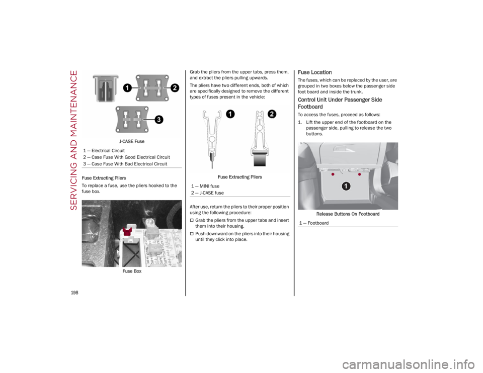
J-CASE Fuse
Fuse Extracting Pliers
To replace a fuse, use the pliers hooked to the
fuse box.
Fuse Box Grab the pliers from the upper tabs, press them,
and extract the pliers pulling upwards.
The pliers have two different ends, both of which
are specifically designed to remove the different
types of fuses present in the vehicle:
Fuse Extracting Pliers
After use, return the pliers to their proper position
using the following procedure:
Grab the pliers from the upper tabs and insert
them into their housing.
Push downward on the pliers into their housing
until they click into place.
Fuse Location
The fuses, which can be replaced by the user, are
grouped in two boxes below the passenger side
foot board and inside the trunk.
Control Unit Under Passenger Side
Footboard
To access the fuses, proceed as follows:
1. Lift the upper end of the footboard on the passenger side, pulling to release the two
buttons.
Release Buttons On Footboard
1 — Electrical Circuit
2 — Case Fuse With Good Electrical Circuit
3 — Case Fuse With Bad Electrical Circuit
1 — MINI fuse
2 — J-CASE fuse
1 — Footboard
22_GA_OM_EN_USC_t.book Page 198
Page 208 of 248

SERVICING AND MAINTENANCE
206
Puddle Lights On Door Panel
See the following steps to replace:
1. Open the door and remove the puddle light assembly, using a suitable tool.
Puddle Light Indent
2. Open protective cover up and remove the bulb pulling out of the connector.
Cover And Bulb Removal Direction 3. Install bulb, making sure that it is correctly
inserted fully.
4. Close the protective cover on the lens.
5. Install puddle light in the correct position, inserting it firstly on one side and then
pressing on the other side until it clicks into
place.
TIRES
TIRE SAFETY INFORMATION
Tire safety information will cover aspects of the
following information: Tire Markings, Tire Identifi -
cation Numbers, Tire Terminology and
Definitions, Tire Pressures, and Tire Loading.
Tire Markings
Tire Markings
NOTE:
P (Passenger) — Metric tire sizing is based on
US design standards. P-Metric tires have the
letter “P” molded into the sidewall preceding
the size designation. Example: P215/65R15
95H.
European — Metric tire sizing is based on
European design standards. Tires designed to
this standard have the tire size molded into the
sidewall beginning with the section width. The
letter "P" is absent from this tire size
designation. Example: 215/65R15 96H.
LT (Light Truck) — Metric tire sizing is based on
US design standards. The size designation for
LT-Metric tires is the same as for P-Metric tires
except for the letters “LT” that are molded into
the sidewall preceding the size designation.
Example: LT235/85R16.
Temporary spare tires are designed for
temporary emergency use only. Temporary
high pressure compact spare tires have the
letter “T” or “S” molded into the sidewall
preceding the size designation. Example:
T145/80D18 103M.
High flotation tire sizing is based on US design
standards and it begins with the tire diameter
molded into the sidewall. Example: 31x10.5
R15 LT.
1 — US DOT Safety Standards Code
(TIN)
2 — Size Designation
3 — Service Description
4 — Maximum Load
5 — Maximum Pressure
6 — Treadwear, Traction and
Temperature Grades
22_GA_OM_EN_USC_t.book Page 206