2022 ALFA ROMEO GIULIA suspension
[x] Cancel search: suspensionPage 119 of 248

117
(Continued)
PARKSENSE WARNING DISPLAY
Parking sensor faults, if any, will be indicated
when REVERSE is engaged by a message on the
instrument cluster display
Ú
page 70.
In case of system failure, a dedicated message
appears on the instrument cluster for about five
seconds.
Cleaning The Front Or Rear Sensors : If the
display shows a message requiring the
sensors to be cleaned, make sure that the
outer surface and the underside of the front
and rear fascias/bumpers are free of debris
(e.g. snow, mud, ice, etc.). Once these areas
are clear, place the ignition in the OFF position,
then return it to ON/RUN. If the message is still
displayed, contact an authorized dealer.
Audio System Not Available : If the display
shows a message that the audio system is not
available, it means that the acoustic signal will
be emitted by the instrument panel, and not
through the vehicle’s speakers.
PARKSENSE SYSTEM USAGE
P
RECAUTIONS
NOTE:
Some conditions may influence the performance
of the ParkSense system:
Reduced sensor sensitivity could be due to the
presence of ice, snow, mud, or thick paint on
the surface of the sensor.
The sensors may detect a false obstacle (echo
interference) due to mechanical interference,
for example when washing the vehicle or in
extreme weather.
The signals sent by the sensors can be altered
by the presence of ultrasonic systems (e.g.
pneumatic brake systems of trucks or
pneumatic drills) near the vehicle.
System performance can be influenced by the
position of the sensors. For example, due to a
change in the ride setting (caused by wear to
the shock absorbers or suspension), by
changing tires, overloading the vehicle or
operations that require the vehicle to be
lowered.
Be sure not to place bumper stickers or other
adhesives over the sensors as this will affect
system performance.
LANE DEPARTURE
WARNING (LDW) SYSTEM —
IF EQUIPPED
LANE DEPARTURE WARNING OPERATION
The Lane Departure Warning system uses a
forward looking camera located on the
windshield to detect lane markings and measure
vehicle position within the lane boundaries.
When one or both lane limits are detected and
the vehicle passes over one without an activated
turn signal, the system emits a visual as well as
an audible signal.
If the vehicle continues to go beyond the line of
the lane without any intervention from the driver,
the surpassed line will light up on the display (left
or right) to urge the driver to bring the vehicle
back into the limits of the lane.
CAUTION!
Projecting loads on the roof of the vehicle
may interfere with the correct operation of
the camera. Before starting, make sure the
load is correctly positioned in order to not
cover the camera operating range.
Do not cover the operating range of the
camera with stickers or other objects.
Do not tamper with nor operate on the
camera. Do not close the openings in the
aesthetic cover located under the interior
rearview mirror. In the event of a failure of
the camera, contact an authorized dealer.
The camera may have limited or absent
operation due to weather conditions such as:
heavy rain, hail, thick fog, heavy snow, or
formation of ice layers on the windshield.
Camera operation may also be compromised
by the presence of dust, condensation, dirt
or ice on the windshield, by traffic conditions
(e.g. vehicles that are driving not aligned with
yours, vehicle driving in a transverse or
opposite way on the same lane, bend with a
small radius of curvature), by road surface
conditions and by driving conditions (e.g.
off-road driving). Make sure the windshield is
always clean. Use specific detergents and
clean cloths to avoid scratching the
windshield. The camera operation may also
be limited or absent in some driving, traffic
and road surface conditions.
22_GA_OM_EN_USC_t.book Page 117
Page 127 of 248

125
VEHICLE LOADING
CERTIFICATION LABEL
As required by National Highway Traffic Safety
Administration regulations, your vehicle has a
certification label affixed to the driver's side door
or pillar.
This label contains the month and year of
manufacture, Gross Vehicle Weight Rating
(GVWR), Gross Axle Weight Rating (GAWR) front
and rear, and Vehicle Identification Number (VIN).
A Month-Day-Hour (MDH) number is included on
this label and indicates the Month, Day and Hour
of manufacture. The bar code that appears on the
bottom of the label is your VIN.
Gross Vehicle Weight Rating (GVWR)
The GVWR is the total permissible weight of your
vehicle including driver, passengers, vehicle,
options and cargo. The label also specifies
maximum capacities of front and rear axle
systems (GAWR). Total load must be limited so
GVWR and front and rear GAWR are not
exceeded.
Payload
The payload of a vehicle is defined as the
allowable load weight a truck can carry, including
the weight of the driver, all passengers, options
and cargo.
Gross Axle Weight Rating (GAWR)
The GAWR is the maximum permissible load on
the front and rear axles. The load must be
distributed in the cargo area so that the GAWR of
each axle is not exceeded.Each axle GAWR is determined by the
components in the system with the lowest load
carrying capacity (axle, springs, tires or wheels).
Heavier axles or suspension components
sometimes specified by purchasers for increased
durability do not necessarily increase the
vehicle's GVWR.
Tire Size
The tire size on the Vehicle Certification Label
represents the actual tire size on your vehicle.
Replacement tires must be equal to the load
capacity of this tire size.
Rim Size
This is the rim size that is appropriate for the tire
size listed.
Inflation Pressure
This is the cold tire inflation pressure for your
vehicle for all loading conditions up to full GAWR.
Curb Weight
The curb weight of a vehicle is defined as the total
weight of the vehicle with all fluids, including
vehicle fuel, at full capacity conditions, and with
no occupants or cargo loaded into the vehicle.
The front and rear curb weight values are
determined by weighing your vehicle on a
commercial scale before any occupants or cargo
are added.
Loading
The actual total weight and the weight of the front
and rear of your vehicle at the ground can best be
determined by weighing it when it is loaded and
ready for operation.
The entire vehicle should first be weighed on a
commercial scale to ensure that the GVWR has
not been exceeded. The weight on the front and
rear of the vehicle should then be determined
separately to be sure that the load is properly
distributed over the front and rear axle. Weighing
the vehicle may show that the GAWR of either the
front or rear axles has been exceeded but the
total load is within the specified GVWR. If so,
weight must be shifted from front to rear or rear
to front as appropriate until the specified weight
limitations are met. Store the heavier items down
low and be sure that the weight is distributed
equally. Stow all loose items securely before
driving.
Improper weight distributions can have an
adverse effect on the way your vehicle steers and
handles and the way the brakes operate.
TRAILER TOWING
Trailer towing is not recommended for this
vehicle.
CAUTION!
Do not load your vehicle any heavier than the
GVWR or the maximum front and rear GAWR. If
you do, parts on your vehicle can break, or it
can change the way your vehicle handles. This
could cause you to lose control. Also
overloading can shorten the life of your
vehicle.
22_GA_OM_EN_USC_t.book Page 125
Page 132 of 248

SAFETY
130
DYNAMIC STEERING TORQUE (DST)
DST uses the integration of the Electronic
Stability Control (ESC) system with the electric
power steering to increase the safety level of the
whole vehicle.
In critical situations (braking on surfaces with
different grip conditions), the ESC system
controls the steering through the DST function to
implement an additional torque contribution on
the steering wheel in order to suggest the most
correct maneuver to the driver.
The coordinated action of the brakes and
steering increases the sensation of safety and
control of the vehicle.
NOTE:
The DST feature is only meant to help the driver
realize the correct course of action through small
torques on the steering wheel, which means the
effectiveness of the DST feature is highly depen-
dent on the driver’s sensitivity and overall reac -
tion to the applied torque. It is very important to
realize that this feature will not steer the vehicle,
meaning the driver is still responsible for steering
the vehicle.
DRIVE TRAIN CONTROL (DTC) SYSTEM —
I
F EQUIPPED
Some models of this vehicle are equipped with an
All-Wheel Drive (AWD) system, which offers an
optimal drive for countless driving conditions and
road surfaces. The system reduces the slipping of
the tires to a minimum, automatically
redistributing the torque to the front and rear
wheels as needed. To maximize fuel savings, the vehicle with AWD
automatically passes to Rear-Wheel Drive (RWD)
when the road and environmental conditions are
such that they wouldn't cause the tires to slip.
When the road and environmental conditions
require better traction, the vehicle automatically
goes to AWD mode.
NOTE:
If the system failure symbol switches on, after
starting the engine or while driving, it means that
the AWD system is not working properly. If the
warning message activates frequently, it is
recommended to carry out the maintenance
operations.
ELECTRONIC STABILITY CONTROL (ESC)
The ESC system improves the directional control
and stability of the vehicle in various driving
conditions.
The ESC system corrects the vehicle’s understeer
and oversteer, distributing the brake force on the
appropriate wheels. The torque supplied by the
engine can also be reduced in order to maintain
control of the vehicle.
Oversteer
occurs when the vehicle is turning
more than it should according to the angle of
the steering wheel.
Understeer occurs when the vehicle is turning
less than it should according to the angle of
the steering wheel.
The ESC system uses sensors installed on the
vehicle to determine the path that the driver
intends to follow and compares it with the
vehicle’s effective path. When the real path
deviates from the desired path, the ESC system
intervenes to counteract the above conditions. System Intervention
The intervention of the system is indicated by the
flashing of the ESC Warning Light on the
instrument panel, to inform the driver that the
vehicle stability and grip are critical.
WARNING!
Electronic Stability Control (ESC) cannot
prevent the natural laws of physics from
acting on the vehicle, nor can it increase the
traction afforded by prevailing road
conditions. ESC cannot prevent accidents,
including those resulting from excessive
speed in turns, driving on very slippery
surfaces, or hydroplaning. ESC also cannot
prevent accidents resulting from loss of
vehicle control due to inappropriate driver
input for the conditions. Only a safe, attentive,
and skillful driver can prevent accidents. The
capabilities of an ESC equipped vehicle must
never be exploited in a reckless or dangerous
manner which could jeopardize the user’s
safety or the safety of others.
Vehicle modifications, or failure to properly
maintain your vehicle, may change the
handling characteristics of your vehicle, and
may negatively affect the performance of the
ESC system. Changes to the steering system,
suspension, braking system, tire type and
size or wheel size may adversely affect ESC
performance. Improperly inflated and
unevenly worn tires may also degrade ESC
performance. Any vehicle modification or
poor vehicle maintenance that reduces the
effectiveness of the ESC system can
increase the risk of loss of vehicle control,
vehicle rollover, personal injury and death.
22_GA_OM_EN_USC_t.book Page 130
Page 181 of 248
179
(Continued)
MANUAL PARK RELEASE
See an authorized dealer to disengage the
manual park release lever.
TOWING A DISABLED
VEHICLE
This section describes procedures for towing a
disabled vehicle using a commercial towing
service.The operators of the assistance vehicle must be
informed with regard to the vehicle's minimum
height from ground in order to avoid contact
between the ends of the fascia/bumper with the
equipment of the breakdown truck.
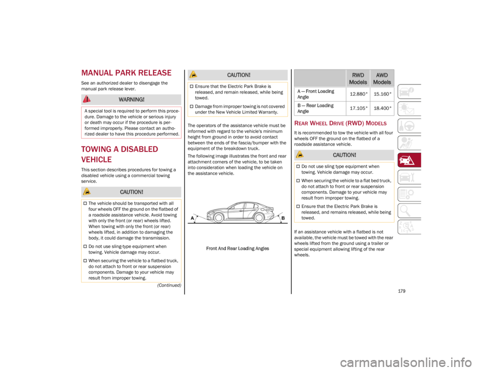
The following image illustrates the front and rear
attachment corners of the vehicle, to be taken
into consideration when loading the vehicle on
the assistance vehicle.
Front And Rear Loading Angles
REAR WHEEL DRIVE (RWD) MODELS
It is recommended to tow the vehicle with all four
wheels OFF the ground on the flatbed of a
roadside assistance vehicle.
If an assistance vehicle with a flatbed is not
available, the vehicle must be towed with the rear
wheels lifted from the ground using a trailer or
special equipment allowing lifting of the rear
wheels.
WARNING!
A special tool is required to perform this proce -
dure. Damage to the vehicle or serious injury
or death may occur if the procedure is per -
formed improperly. Please contact an autho -
rized dealer to have this procedure performed.
CAUTION!
The vehicle should be transported with all
four wheels OFF the ground on the flatbed of
a roadside assistance vehicle. Avoid towing
with only the front (or rear) wheels lifted.
When towing with only the front (or rear)
wheels lifted, in addition to damaging the
body, it could damage the transmission.
Do not use sling-type equipment when
towing. Vehicle damage may occur.
When securing the vehicle to a flatbed truck,
do not attach to front or rear suspension
components. Damage to your vehicle may
result from improper towing.
Ensure that the Electric Park Brake is
released, and remain released, while being
towed.
Damage from improper towing is not covered
under the New Vehicle Limited Warranty.
CAUTION!RWD
ModelsAWD
Models
A — Front Loading
Angle 12.880° 15.160°
B — Rear Loading
Angle 17.105° 18.400°
CAUTION!
Do not use sling type equipment when
towing. Vehicle damage may occur.
When securing the vehicle to a flat bed truck,
do not attach to front or rear suspension
components. Damage to your vehicle may
result from improper towing.
Ensure that the Electric Park Brake is
released, and remains released, while being
towed.
22_GA_OM_EN_USC_t.book Page 179
Page 217 of 248
215
(Continued)
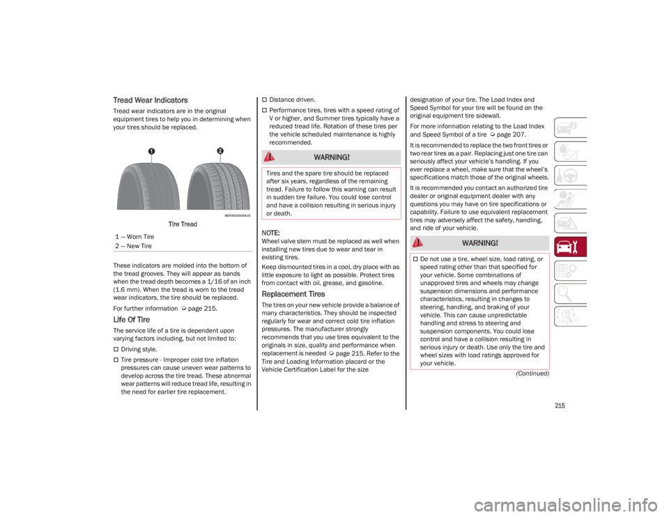
Tread Wear Indicators
Tread wear indicators are in the original
equipment tires to help you in determining when
your tires should be replaced.Tire Tread
These indicators are molded into the bottom of
the tread grooves. They will appear as bands
when the tread depth becomes a 1/16 of an inch
(1.6 mm). When the tread is worn to the tread
wear indicators, the tire should be replaced.
For further information
Ú
page 215.
Life Of Tire
The service life of a tire is dependent upon
varying factors including, but not limited to:
Driving style.
Tire pressure - Improper cold tire inflation
pressures can cause uneven wear patterns to
develop across the tire tread. These abnormal
wear patterns will reduce tread life, resulting in
the need for earlier tire replacement.
Distance driven.
Performance tires, tires with a speed rating of
V or higher, and Summer tires typically have a
reduced tread life. Rotation of these tires per
the vehicle scheduled maintenance is highly
recommended.
NOTE:
Wheel valve stem must be replaced as well when
installing new tires due to wear and tear in
existing tires.
Keep dismounted tires in a cool, dry place with as
little exposure to light as possible. Protect tires
from contact with oil, grease, and gasoline.
Replacement Tires
The tires on your new vehicle provide a balance of
many characteristics. They should be inspected
regularly for wear and correct cold tire inflation
pressures. The manufacturer strongly
recommends that you use tires equivalent to the
originals in size, quality and performance when
replacement is needed
Ú
page 215. Refer to the
Tire and Loading Information placard or the
Vehicle Certification Label for the size designation of your tire. The Load Index and
Speed Symbol for your tire will be found on the
original equipment tire sidewall.
For more information relating to the Load Index
and Speed Symbol of a tire
Ú
page 207.
It is recommended to replace the two front tires or
two rear tires as a pair. Replacing just one tire can
seriously affect your vehicle’s handling. If you
ever replace a wheel, make sure that the wheel’s
specifications match those of the original wheels.
It is recommended you contact an authorized tire
dealer or original equipment dealer with any
questions you may have on tire specifications or
capability. Failure to use equivalent replacement
tires may adversely affect the safety, handling,
and ride of your vehicle.
1 — Worn Tire
2 — New Tire
WARNING!
Tires and the spare tire should be replaced
after six years, regardless of the remaining
tread. Failure to follow this warning can result
in sudden tire failure. You could lose control
and have a collision resulting in serious injury
or death.
WARNING!
Do not use a tire, wheel size, load rating, or
speed rating other than that specified for
your vehicle. Some combinations of
unapproved tires and wheels may change
suspension dimensions and performance
characteristics, resulting in changes to
steering, handling, and braking of your
vehicle. This can cause unpredictable
handling and stress to steering and
suspension components. You could lose
control and have a collision resulting in
serious injury or death. Use only the tire and
wheel sizes with load ratings approved for
your vehicle.
22_GA_OM_EN_USC_t.book Page 215
Page 220 of 248
SERVICING AND MAINTENANCE
218
Summer tires do not contain the all season
designation or mountain/snowflake symbol on
the tire sidewall. Use Summer tires only in sets of
four; failure to do so may adversely affect the
safety and handling of your vehicle.
Snow Tires
Some areas of the country require the use of
snow tires during the Winter. Snow tires can be
identified by a “mountain/snowflake” symbol on
the tire sidewall.If you need snow tires, select tires
equivalent in size and type to the
original equipment tires. Use snow tires
only in sets of four; failure to do so may
adversely affect the safety and handling of your
vehicle.
Snow tires generally have lower speed ratings
than what was originally equipped with your
vehicle and should not be operated at sustained
speeds over 75 mph (120 km/h). For speeds
above 75 mph (120 km/h) refer to original equipment or an authorized tire dealer for
recommended safe operating speeds, loading
and cold tire inflation pressures. While studded tires improve performance on ice,
skid and traction capability on wet or dry surfaces
may be poorer than that of non-studded tires.
Some states prohibit studded tires; therefore,
local laws should be checked before using these
tire types.
SNOW TRACTION DEVICES
Use of traction devices require sufficient
tire-to-body clearance. Follow these recommen
-
dations to guard against damage.
NOTE:
Traction device must be of proper size for the
tire, as recommended by the traction device
manufacturer.
Use on rear tires only.
Due to limited clearance, the following traction
devices are recommended:
For a 255/35R19 tire, use of a snow traction
device with a maximum projection of 7 mm
beyond the tire profile is recommended.
For 225/50R17, 225/45R18 or 225/40R19
tires, use of a snow traction device with a
maximum projection of 9 mm beyond the tire
profile is recommended.
For a 265/35R19 98V tire, use of a
zero-clearance snow traction device
recommended.
It is not possible to install traction devices on
285/30R19 tires.
WARNING!
Do not use Summer tires in snow/ice
conditions. You could lose vehicle control,
resulting in severe injury or death. Driving too
fast for conditions also creates the possibility
of loss of vehicle control.
CAUTION!
To avoid damage to your vehicle or tires,
observe the following precautions:
Because of restricted traction device
clearance between tires and other
suspension components, it is important that
only traction devices in good condition are
used. Broken devices can cause serious
damage. Stop the vehicle immediately if
noise occurs that could indicate device
breakage. Remove the damaged parts of the
device before further use.
Install device as tightly as possible and then
retighten after driving about ½ mile (0.8 km).
Autosock devices do not require
retightening.
Do not exceed 30 mph (48 km/h).
Drive cautiously and avoid severe turns and
large bumps, especially with a loaded
vehicle.
Do not drive for a prolonged period on dry
pavement.
Observe the traction device manufacturer’s
instructions on the method of installation,
operating speed, and conditions for use.
Always use the suggested operating speed of
the device manufacturer’s if it is less than
30 mph (48 km/h).
Do not use traction devices on a compact
spare tire.
22_GA_OM_EN_USC_t.book Page 218
Page 228 of 248

TECHNICAL SPECIFICATIONS
226
BRAKES
SUSPENSION
STEERING SYSTEM
ModelFront brakesRear brakesParking brake
2.0L Engine and 2.9L EngineDiscDiscElectric
CAUTION!
Water, ice and salt spread on the roads may deposit on the brake discs, reducing braking efficiency the first time the brakes are applied.
To obtain the maximum efficiency of the braking system, a bedding-in period of about 300 miles (500 km) is needed: during this period it is better to
avoid sharp, repeated and prolonged braking.
ModelFrontRear
2.0L Engine and 2.9L Engine Independent wheel
double-wishbone suspension Independent wheel with multi-link
system
ModelCurb-to-curb turning circleType
2.0L Engine 35.50 ft (10.80 m)Rack and pinion with electric power
steering
2.9L Engine 37.10 ft (11.30 m)Rack and pinion with electric power
steering
22_GA_OM_EN_USC_t.book Page 226
Page 241 of 248

239
INDEX
A
Accessories Purchased By The Owner.......... 3
Active Blind Spot Assist .............................134
Active Safety Systems ................................ 129
Active Torque Vectoring (ATV) System ......129
Adaptive Cruise Control (ACC)
(Cruise Control) ............................................ 97Off ........................................................... 101
On............................................................101
Additives, Fuel ............................................ 230
Adjust Forward.............................................. 31, 33
Rearward ........................................... 31, 33
Air Bag......................................................... 150 Air Bag Operation ...................................151Air Bag Warning Light ............................149
Driver Knee Air Bag................................ 152Enhanced Accident Response .....155, 181
Event Data Recorder (EDR) ...................181
Front Air Bag...........................................150
If Deployment Occurs ............................154
Knee Impact Bolsters ............................152
Maintaining Your Air Bag System.......... 157
Maintenance ..........................................157
Redundant Air Bag Warning Light.........150
Side Air Bags ..........................................152
Transporting Pets...................................166
Air Bag Light ......................................149, 166
Air Pressure Tires ........................................................212
Alarm Security Alarm .......................................... 24 Alfa Active Suspension (AAS) .......................94
Alfa DNA System ...........................................91
Anti-Lock Braking (ABS) System ............... 129
Anti-Lock Warning Light ...............................72
Automatic Door Locks ..................................27
Automatic Headlights ...................................43
Automatic Temperature Control (ATC) ........49
Automatic Transmission ..............................86
Auxiliary Driving Systems .......................... 132
B
Back-Up Camera ........................................ 122
Battery ..................................................74, 190 Charging System Light .............................74
Battery Recharging .................................... 191
Belts, Seat .................................................. 166
Blind Spot Monitoring ............................... 132
Bodywork (Cleaning And Maintenance) ... 221
B-Pillar Location......................................... 209
Brake System Warning Light .................................... 70, 72
Brakes ........................................................ 226 Brake Fluid Level................................... 190
Bulbs, Light ................................................ 167
C
Camera, Rear ............................................. 122
Carbon Monoxide Warning .............. 167, 168
Cargo Tie-Downs ...........................................62
Certification Label ..................................... 125
Chart, Tire Sizing........................................ 207 Check Engine Light (Malfunction
Indicator Light) ............................................. 80
Checking Levels ................................ 187, 188
Checking Your Vehicle For Safety ............. 165
Checks, Safety ........................................... 165
Child Restraint ........................................... 157
Child Restraints
Booster Seats ........................................ 159
Child Seat Installation ........................... 164
How To Stow An unused ALR SeatBelt ..................................................... 163
Infant And Child Restraints ................... 158
LATCH Positions ..................................... 160
Lower Anchors And Tethers For Children .............................................. 160
Older Children And Child Restraints ..... 159
Seating Positions ................................... 160
Using The Top Tether Anchorage.......... 165
Clean Air Gasoline ..................................... 230
Cleaning Wheels.................................................... 217
Climate Control ......................................48, 54
Compact Spare Tire ................................... 216
Contract, Service........................................ 236
Cruise Control (Speed Control) ................... 97
Customer Assistance ................................. 236
D
Daytime Running Lights .............................. 42
Deck Lid Power Release ......................................... 61
Defroster, Windshield ................................ 166
22_GA_OM_EN_USC_t.book Page 239