2022 ALFA ROMEO GIULIA light
[x] Cancel search: lightPage 190 of 248
SERVICING AND MAINTENANCE
188
CHECKING LEVELS — 2.9L ENGINE
E
NGINE OIL
The engine oil level can be seen on the
instrument cluster display every time the engine
is started, or on the Information and
Entertainment system display by activating on
the main menu (MENU button) the following
functions in sequence: “Vehicle Information”;
“Engine Oil”. Check on the display using the 6 notches that the
oil level is between the MIN and MAX level:
1 notch MIN level, 6 notches MAX level.
NOTE:
Use care when filling under hood fluids such as
engine oil, windshield washer fluid, antifreeze
etc. to minimize spillage onto the top of the
engine. Any excess fluid that is spilled onto the
top of the engine should be removed using
compressed air or an absorbent cloth.If the oil level is close to or below the MIN mark,
add oil gradually through the filler, (refer to
“Top-Up And Oil Level Indication Update On
Display” in this section) considering that each
notch shown on the display corresponds to
approximately 8.8 fl oz (250 ml).
The oil level can also be checked manually on
2.9L Engines.
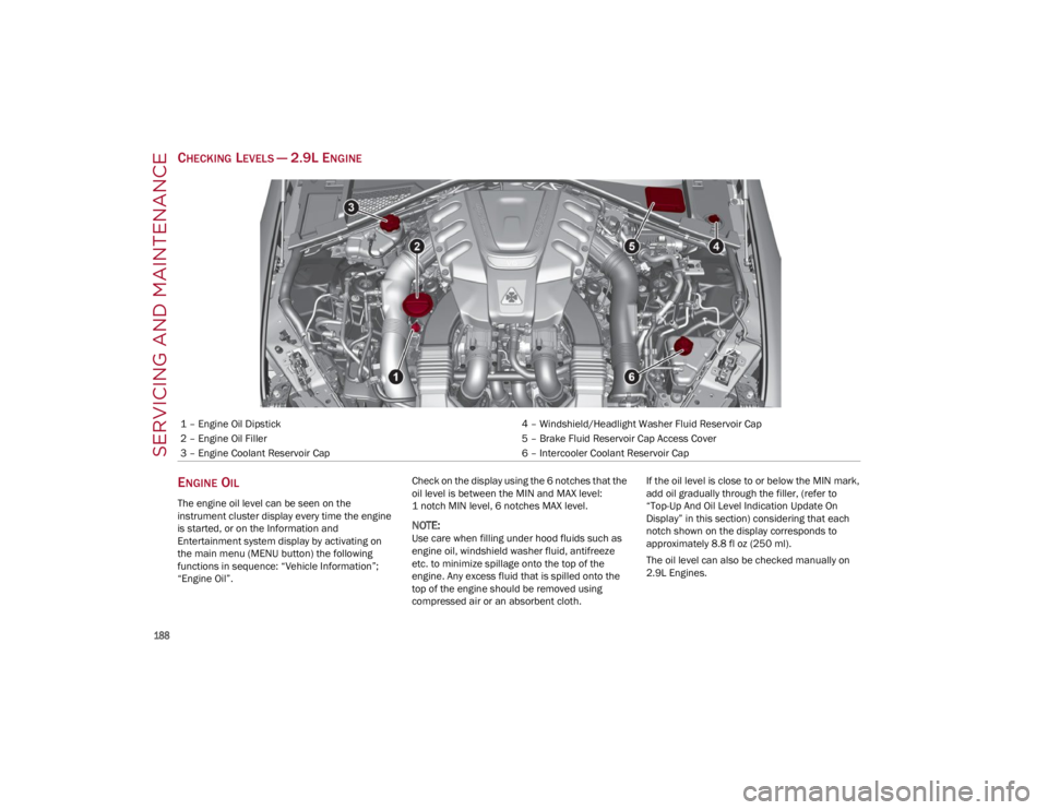
1 – Engine Oil Dipstick
4 – Windshield/Headlight Washer Fluid Reservoir Cap
2 – Engine Oil Filler 5 – Brake Fluid Reservoir Cap Access Cover
3 – Engine Coolant Reservoir Cap 6 – Intercooler Coolant Reservoir Cap
22_GA_OM_EN_USC_t.book Page 188
Page 192 of 248
SERVICING AND MAINTENANCE
190
(Continued)
ENGINE COOLANT
If the level is too low, remove the cap of reservoir
and add the fluid described on
Ú
page 233.
WASHER FLUID FOR WINDSHIELD/
H
EADLIGHTS
The windshield and headlights washer fluid
reservoir has a telescopic filler.
If the level is too low, remove reservoir cap and lift
the filler. Then, add the fluid described on
Ú
page 233.
NOTE:
Use care when filling under hood fluids such as
engine oil, windshield washer fluid, antifreeze
etc. to minimize spillage onto the top of the
engine. Any excess fluid that is spilled onto the
top of the engine should be removed using
compressed air or an absorbent cloth.
NOTE:
The headlight washing system will not work if the
liquid level is low (as indicated by the symbol on
the instrument cluster display). On vehicles
equipped with headlight washers, there is a refer -
ence notch on the dipstick: ONLY the windshield/
rear window washer operates with the level below
this reference.
BRAKE FLUID
Check that the fluid is at the maximum level. If
the fluid level in the tank is low, contact an
authorized dealer to have the system checked.
AUTOMATIC TRANSMISSION ACTIVATION
S
YSTEM OIL
The transmission control oil level should only be
checked at an authorized dealer.
USEFUL ADVICE FOR EXTENDING THE
L
IFE OF YOUR BATTERY
To avoid draining your battery and make it last
longer, observe the following instructions:
When you park the car, ensure that the doors
and trunk are closed properly to prevent any
lights from remaining on inside the
passenger's compartment.
Do not keep accessories (e.g. radio, hazard
warning lights, etc.) switched on for a long time
when the engine is not running.
Before performing any operation on the
electrical system, disconnect the negative
battery cable.
If you wish to install electrical accessories after
purchasing the car that require permanent
electrical supply (e.g. alarm, etc.), or accessories
which influence the electrical supply
requirements, contact an authorized dealer,
whose qualified staff will evaluate the overall
electrical consumption.
NOTE:
After the battery is disconnected, the steering
must be initialized. The warning light on the
instrument panel switches on to indicate this. To
carry out this procedure, simply turn the steering
wheel all the way from one end to the other, and
then turn it back to the central position.
BATTERY
The battery does not require the electrolyte to be
topped up with distilled water. A periodic check
carried out at an authorized dealer, however, is
necessary to check efficiency.
Follow the battery manufacturer's instructions for
maintenance.
Replacing The Battery
If necessary, replace the battery with another
original battery with the same specifications.
Follow the battery manufacturer’s instructions for
maintenance.
CAUTION!
If the charge level remains under 50% for a
long time, the battery may be damaged by
sulphation, reducing its capacity and
efficiency during a vehicle start. The battery is
also more prone to the risk of freezing (at
temperatures as high as 14°F (-10°C).
WARNING!
Battery acid is a corrosive solution and can
burn or even blind you. Do not allow battery
acid to contact your eyes, skin, or clothing.
Do not lean over a battery when attaching
clamps
Ú
page 177. If acid splashes in eyes
or on skin, flush the area immediately with
large amounts of water.
Battery gas is flammable and explosive.
Keep flame or sparks away from the battery.
Do not use a booster battery or any other
booster source with an output greater than
12 Volts. Do not allow cable clamps to touch
each other.
22_GA_OM_EN_USC_t.book Page 190
Page 204 of 248
SERVICING AND MAINTENANCE
202
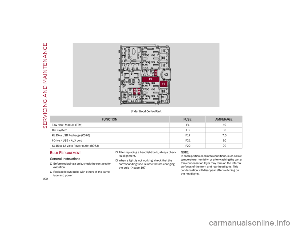
Under Hood Control Unit
BULB REPLACEMENT
General Instructions
Before replacing a bulb, check the contacts for
oxidation.
Replace blown bulbs with others of the same
type and power.
After replacing a headlight bulb, always check
its alignment.
When a light is not working, check that the
corresponding fuse is intact before changing
the bulb
Ú
page 197.
NOTE:
In some particular climate conditions, such as low
temperature, humidity, or after washing the car, a
thin condensation layer may form on the internal
surfaces of the front and rear headlights. This
condensation will disappear after switching on
the headlights.
FUNCTIONFUSEAMPERAGE
Tow Hook Module (TTM)
F140
Hi-Fi system F830
KL15/a USB Recharge (C070) F177.5
I-Drive / USB / AUX port F2110
KL15/a 12 Volts Power outlet (R053) F2220
22_GA_OM_EN_USC_t.book Page 202
Page 205 of 248
203
Types Of Bulbs
Replacement Bulbs
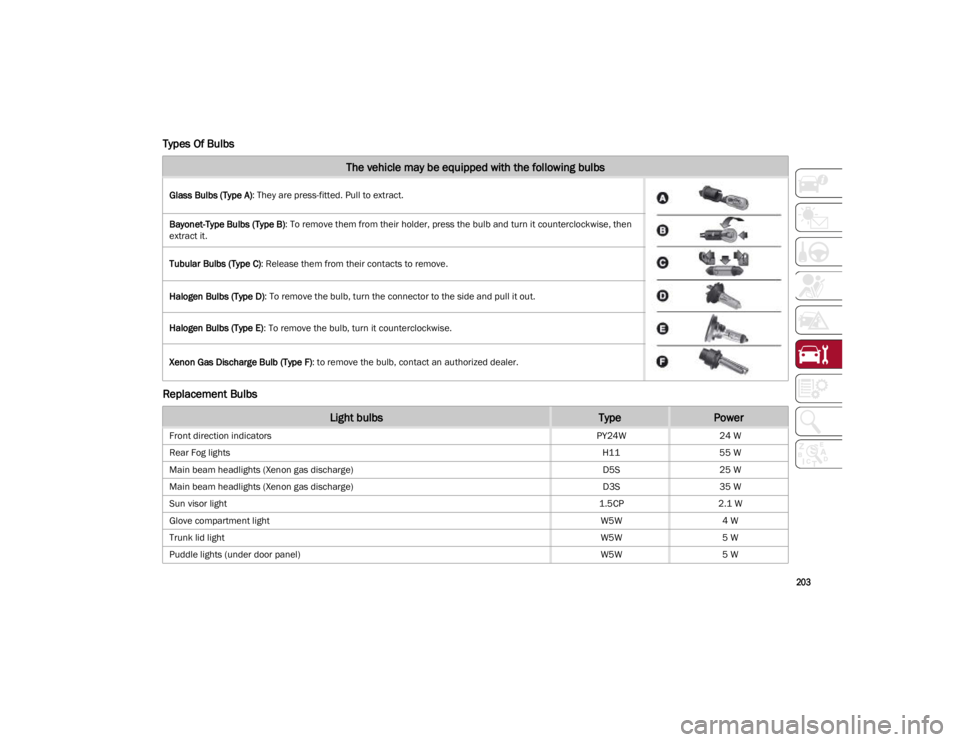
The vehicle may be equipped with the following bulbs
Glass Bulbs (Type A): They are press-fitted. Pull to extract.
Bayonet-Type Bulbs (Type B) : To remove them from their holder, press the bulb and turn it counterclockwise, then
extract it.
Tubular Bulbs (Type C) : Release them from their contacts to remove.
Halogen Bulbs (Type D) : To remove the bulb, turn the connector to the side and pull it out.
Halogen Bulbs (Type E) : To remove the bulb, turn it counterclockwise.
Xenon Gas Discharge Bulb (Type F) : to remove the bulb, contact an authorized dealer.
Light bulbsTypePower
Front direction indicators PY24W24 W
Rear Fog lights H1155 W
Main beam headlights (Xenon gas discharge) D5S25 W
Main beam headlights (Xenon gas discharge) D3S35 W
Sun visor light 1.5CP2.1 W
Glove compartment light W5W4 W
Trunk lid light W5W5 W
Puddle lights (under door panel) W5W5 W
22_GA_OM_EN_USC_t.book Page 203
Page 206 of 248
SERVICING AND MAINTENANCE
204
Replacing Exterior Bulbs
NOTE:
Only replace the bulb when the engine is off. Also
ensure that the engine is cold, to prevent the risk
of burns.
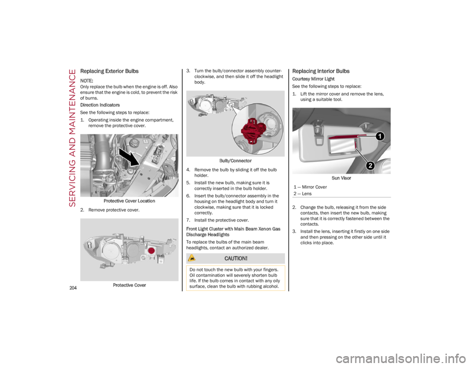
Direction Indicators
See the following steps to replace:
1. Operating inside the engine compartment,remove the protective cover.
Protective Cover Location
2. Remove protective cover.
Protective Cover 3. Turn the bulb/connector assembly counter
-
clockwise, and then slide it off the headlight
body.
Bulb/Connector
4. Remove the bulb by sliding it off the bulb holder.
5. Install the new bulb, making sure it is correctly inserted in the bulb holder.
6. Insert the bulb/connector assembly in the housing on the headlight body and turn it
clockwise, making sure that it is locked
correctly.
7. Install the protective cover.
Front Light Cluster with Main Beam Xenon Gas
Discharge Headlights
To replace the bulbs of the main beam
headlights, contact an authorized dealer.
Replacing Interior Bulbs
Courtesy Mirror Light
See the following steps to replace:
1. Lift the mirror cover and remove the lens, using a suitable tool.
Sun Visor
2. Change the bulb, releasing it from the side contacts, then insert the new bulb, making
sure that it is correctly fastened between the
contacts.
3. Install the lens, inserting it firstly on one side and then pressing on the other side until it
clicks into place.
CAUTION!
Do not touch the new bulb with your fingers.
Oil contamination will severely shorten bulb
life. If the bulb comes in contact with any oily
surface, clean the bulb with rubbing alcohol.
1 — Mirror Cover
2 — Lens
22_GA_OM_EN_USC_t.book Page 204
Page 207 of 248
205
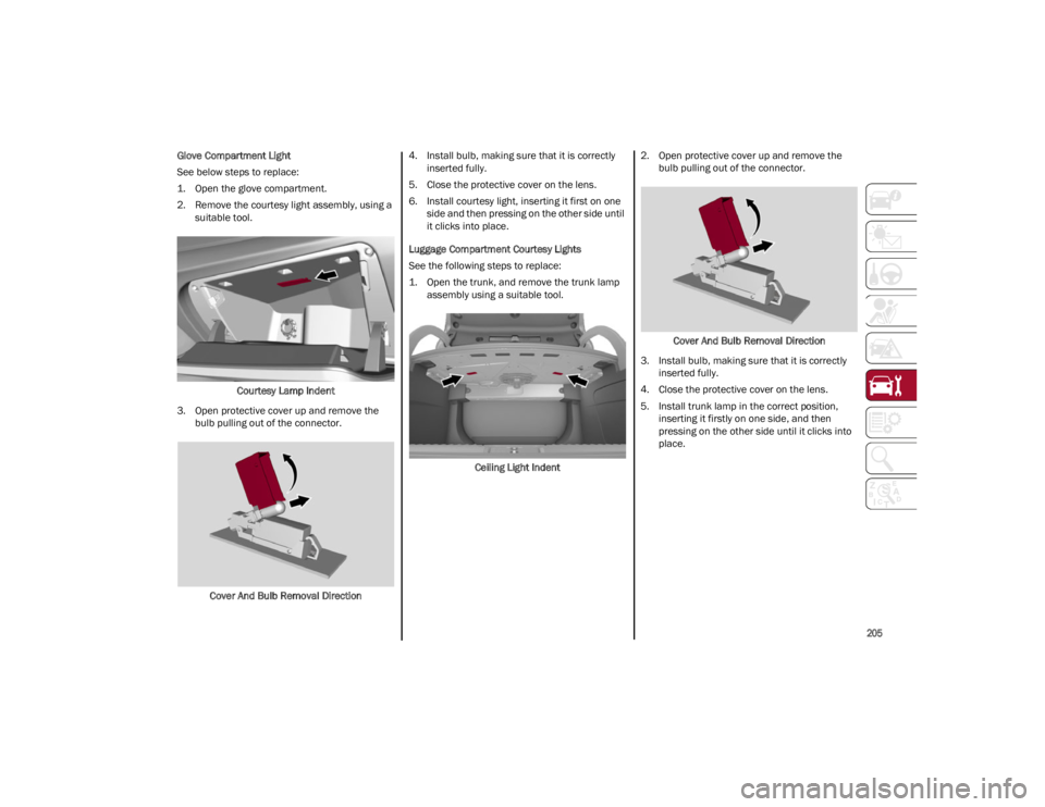
Glove Compartment Light
See below steps to replace:
1. Open the glove compartment.
2. Remove the courtesy light assembly, using asuitable tool.
Courtesy Lamp Indent
3. Open protective cover up and remove the bulb pulling out of the connector.
Cover And Bulb Removal Direction 4. Install bulb, making sure that it is correctly
inserted fully.
5. Close the protective cover on the lens.
6. Install courtesy light, inserting it first on one side and then pressing on the other side until
it clicks into place.
Luggage Compartment Courtesy Lights
See the following steps to replace:
1. Open the trunk, and remove the trunk lamp assembly using a suitable tool.
Ceiling Light Indent 2. Open protective cover up and remove the
bulb pulling out of the connector.
Cover And Bulb Removal Direction
3. Install bulb, making sure that it is correctly inserted fully.
4. Close the protective cover on the lens.
5. Install trunk lamp in the correct position, inserting it firstly on one side, and then
pressing on the other side until it clicks into
place.
22_GA_OM_EN_USC_t.book Page 205
Page 208 of 248

SERVICING AND MAINTENANCE
206
Puddle Lights On Door Panel
See the following steps to replace:
1. Open the door and remove the puddle light assembly, using a suitable tool.
Puddle Light Indent
2. Open protective cover up and remove the bulb pulling out of the connector.
Cover And Bulb Removal Direction 3. Install bulb, making sure that it is correctly
inserted fully.
4. Close the protective cover on the lens.
5. Install puddle light in the correct position, inserting it firstly on one side and then
pressing on the other side until it clicks into
place.
TIRES
TIRE SAFETY INFORMATION
Tire safety information will cover aspects of the
following information: Tire Markings, Tire Identifi -
cation Numbers, Tire Terminology and
Definitions, Tire Pressures, and Tire Loading.
Tire Markings
Tire Markings
NOTE:
P (Passenger) — Metric tire sizing is based on
US design standards. P-Metric tires have the
letter “P” molded into the sidewall preceding
the size designation. Example: P215/65R15
95H.
European — Metric tire sizing is based on
European design standards. Tires designed to
this standard have the tire size molded into the
sidewall beginning with the section width. The
letter "P" is absent from this tire size
designation. Example: 215/65R15 96H.
LT (Light Truck) — Metric tire sizing is based on
US design standards. The size designation for
LT-Metric tires is the same as for P-Metric tires
except for the letters “LT” that are molded into
the sidewall preceding the size designation.
Example: LT235/85R16.
Temporary spare tires are designed for
temporary emergency use only. Temporary
high pressure compact spare tires have the
letter “T” or “S” molded into the sidewall
preceding the size designation. Example:
T145/80D18 103M.
High flotation tire sizing is based on US design
standards and it begins with the tire diameter
molded into the sidewall. Example: 31x10.5
R15 LT.
1 — US DOT Safety Standards Code
(TIN)
2 — Size Designation
3 — Service Description
4 — Maximum Load
5 — Maximum Pressure
6 — Treadwear, Traction and
Temperature Grades
22_GA_OM_EN_USC_t.book Page 206
Page 209 of 248

207
Tire Sizing Chart
EXAMPLE:
Example Size Designation: P215/65R15XL 95H, 215/65R15 96H, LT235/85R16C, T145/80D18 103M, 31x10.5 R15 LT
P
= Passenger car tire size based on US design standards, or
"....blank...." = Passenger car tire based on European design standards, or
LT = Light truck tire based on US design standards, or
T or S = Temporary spare tire or
31 = Overall diameter in inches (in)
215, 235, 145 = Section width in millimeters (mm)
65, 85, 80 = Aspect ratio in percent (%)
Ratio of section height to section width of tire, or
10.5 = Section width in inches (in)
R = Construction code
"R" means radial construction, or
"D" means diagonal or bias construction
15, 16, 18 = Rim diameter in inches (in)
Service Description:
95 = Load Index
A numerical code associated with the maximum load a tire can carry
H = Speed Symbol
A symbol indicating the range of speeds at which a tire can carry a load corresponding to its load index under certain operating conditions
The maximum speed corresponding to the speed symbol should only be achieved under specified operating conditions (i.e., tire pressure, vehicle
loading, road conditions, and posted speed limits)
Load Identification:
Absence of the following load identification symbols on the sidewall of the tire indicates a Standard Load (SL) tire:
XL = Extra load (or reinforced) tire, or
LL = Light load tire or
C, D, E, F, G = Load range associated with the maximum load a tire can carry at a specified pressure
22_GA_OM_EN_USC_t.book Page 207