Page 25 of 108

INSTRUMENT AND CONTROL FUNCTIONS
3-10
3
EAU00186
CAUTION:_ l
Immediately wipe off spilled fuel
with a clean, dry, soft cloth,
since fuel may deteriorate paint-
ed surfaces or plastic parts.
l
For Germany only: Whenever
replacement is necessary, use a
fuel tank cap of the same spe-
cial design as the original.
_
EAU00191
NOTE:_ If knocking (or pinging) occurs, use
gasoline of a different brand or with a
higher octane grade. _
EAU02955
Fuel tank breather hose Before operating the motorcycle:l
Check the fuel tank breather hose
connection.
l
Check the fuel tank breather hose
for cracks or damage, and replace
it if damaged.
l
Make sure that the end of the fuel
tank breather hose is not blocked,
and clean it if necessary.
EAU03839
Starter (choke) lever “ ” Starting a cold engine requires a richer
air-fuel mixture, which is supplied by
the starter (choke).
Move the lever in direction
a to turn on
the starter (choke).
Move the lever in direction
b to turn off
the starter (choke). Recommended fuel:
Regular unleaded gasoline with a
research octane number of 91 or
higher
Fuel tank capacity:
Total amount:
20 L
Reserve amount:
4.5 L
1. Fuel tank breather hose
1. Starter (choke) lever “ ”
E_4sv.book Page 10 Friday, November 10, 2000 3:03 PM
Page 26 of 108
INSTRUMENT AND CONTROL FUNCTIONS
3-11
3
EAU01698
Seats Rider seat
To remove the rider seat1. Insert the key into the seat lock,
and then turn it as shown.
2. Pull the rider seat off.To install the rider seat
1. Insert the projection on the front of
the rider seat into the seat holder
as shown, and then push the rear
of the seat down to lock it in place.
2. Remove the key.Passenger seat
To remove the passenger seat
1. Remove the rider seat.
2. Pull the passenger seat up.
To install the passenger seat1. Insert the projection on the rear of
the passenger seat and the hooks
on the front of the passenger seat
into the seat holders as shown,
and then push the seat toward the
back.
2. Install the rider seat.
1. Rider seat lock
1. Projection
2. Seat holder
1. Projection
2. Hook (´ 2)
3. Seat holder (´ 3)
E_4sv.book Page 11 Friday, November 10, 2000 3:03 PM
Page 27 of 108
INSTRUMENT AND CONTROL FUNCTIONS
3-12
3
NOTE:_ Make sure that the seats are properly
secured before riding. _
EAU00264
Helmet holder The helmet holder is located under the
rider seat.
To secure a helmet to the helmet
holder
1. Remove the rider seat. (See
page 3-11 for rider seat removal
and installation procedures.)
2. Attach the helmet to the helmet
holder, and then securely install
the seat.
EW000030
WARNING
_ Never ride with a helmet attached to
the helmet holder, since the helmet
may hit objects, causing loss of
control and possibly an accident. _To release the helmet from the hel-
met holder
Remove the rider seat, remove the hel-
met from the helmet holder, and then
install the seat.
1. Helmet holder
E_4sv.book Page 12 Friday, November 10, 2000 3:03 PM
Page 28 of 108
 When placing
a U-LOCK in the stora")
INSTRUMENT AND CONTROL FUNCTIONS
3-13
3
EAU01688
Storage compartment This storage compartment is designed
to hold a genuine Yamaha U-LOCK.
(Other locks may not fit.) When placing
a U-LOCK in the storage compartment,
securely fasten it with the straps. When
the U-LOCK is not in the storage com-
partment, be sure to secure the straps
to prevent losing them.
When storing the owner’s manual or
other documents in the storage com-
partment, be sure to wrap them in a
plastic bag so that they will not get wet.
When washing the motorcycle, be
careful not to let any water enter the
storage compartment.
EAU01862
Adjusting the front fork This front fork is equipped with spring
preload adjusting bolts, rebound damp-
ing force adjusting screws and com-
pression damping force adjusting
screws.
EW000035
WARNING
_ Always adjust both fork legs equal-
ly, otherwise poor handling and loss
of stability may result. _
Spring preload
To increase the spring preload and
thereby harden the suspension, turn
the adjusting bolt on each fork leg in di-
rection
a. To decrease the spring pre-
load and thereby soften the
suspension, turn the adjusting bolt on
each fork leg in direction
b.NOTE:_ Align the appropriate groove on the ad-
justing mechanism with the top of the
front fork cap bolt. _
1. U-LOCK
2. Strap
1. Spring preload adjusting bolt
E_4sv.book Page 13 Friday, November 10, 2000 3:03 PM
Page 29 of 108

INSTRUMENT AND CONTROL FUNCTIONS
3-14
3
CI-10E
Rebound damping force
To increase the rebound damping
force and thereby harden the rebound
damping, turn the adjusting screw on
each fork leg in direction
a. To de-
crease the rebound damping force and
thereby soften the rebound damping,
turn the adjusting screw on each fork
leg in direction
b.CI-02E
Compression damping force
To increase the compression damping
force and thereby harden the compres-
sion damping, turn the adjusting screw
on each fork leg in direction
a. To de-
crease the compression damping force
and thereby soften the compression
damping, turn the adjusting screw on
each fork leg in direction
b.CI-02E
1. Current setting
2. Front fork cap bolt
Setting
Minimum (soft) 5
Standard 4
Maximum (hard) 1
1. Rebound damping force adjusting screwMinimum (soft) 17 clicks in direction
b*
Standard 9 clicks in direction
b*
Maximum (hard) 0 clicks in direction
b*
* With the adjusting screw fully turned in direction
a
1. Compression damping force adjusting screwMinimum (soft) 21 clicks in direction
b*
Standard 12 clicks in direction
b*
Maximum (hard) 0 clicks in direction
b*
* With the adjusting screw fully turned in direction
a
E_4sv.book Page 14 Friday, November 10, 2000 3:03 PM
Page 30 of 108

INSTRUMENT AND CONTROL FUNCTIONS
3-15
3
EC000015
CAUTION:_ Never attempt to turn an adjusting
mechanism beyond the maximum
or minimum settings. _NOTE:_ Although the total number of clicks of a
damping force adjusting mechanism
may not exactly match the above spec-
ifications due to small differences in
production, the actual number of clicks
always represents the entire adjusting
range. To obtain a precise adjustment,
it would be advisable to check the num-
ber of clicks of each damping force ad-
justing mechanism and to modify the
specifications as necessary. _
EAU01699
Adjusting the shock absorber
assembly This shock absorber assembly is
equipped with a spring preload adjust-
ing ring, a rebound damping force ad-
justing knob and a compression
damping force adjusting screw.
EC000015
CAUTION:_ Never attempt to turn an adjusting
mechanism beyond the maximum
or minimum settings. _
Spring preload
To increase the spring preload and
thereby harden the suspension, turn
the adjusting ring in direction
a. To de-
crease the spring preload and thereby
soften the suspension, turn the adjust-
ing ring in direction
b.CI-10E1. Spring preload adjusting ring
2. Position indicator
Setting
Minimum (soft) 1
Standard 4
Maximum (hard) 9
E_4sv.book Page 15 Friday, November 10, 2000 3:03 PM
Page 31 of 108

INSTRUMENT AND CONTROL FUNCTIONS
3-16
3
Rebound damping force
To increase the rebound damping
force and thereby harden the rebound
damping, turn the adjusting knob in di-
rection
a. To decrease the rebound
damping force and thereby soften the
rebound damping, turn the adjusting
knob in direction
b.
CI-03E
Compression damping force
To increase the compression damping
force and thereby harden the compres-
sion damping, turn the adjusting screw
in direction
a. To decrease the com-
pression damping force and thereby
soften the compression damping, turn
the adjusting screw in direction
b.CI-02E
NOTE:_ Although the total number of clicks of a
damping force adjusting mechanism
may not exactly match the above spec-
ifications due to small differences in
production, the actual number of clicks
always represents the entire adjusting
range. To obtain a precise adjustment,
it would be advisable to check the num-
ber of clicks of each damping force ad-
justing mechanism and to modify the
specifications as necessary. _
1. Rebound damping force adjusting knobMinimum (soft) 20 clicks in direction
b*
Standard 10 clicks in direction
b*
Maximum (hard) 0 clicks in direction
b*
* With the adjusting knob fully turned in direction
a
1. Compression damping force adjusting screwMinimum (soft) 0 clicks in direction
a*
Standard 10 clicks in direction
a*
Maximum (hard) 24 clicks in direction
a*
* With the adjusting screw fully turned in direction
b
E_4sv.book Page 16 Friday, November 10, 2000 3:03 PM
Page 32 of 108

INSTRUMENT AND CONTROL FUNCTIONS
3-17
3
EAU00315
WARNING
_ This shock absorber contains high-
ly pressurized nitrogen gas. For
proper handling, read and under-
stand the following information be-
fore handling the shock absorber.
The manufacturer cannot be held re-
sponsible for property damage or
personal injury that may result from
improper handling.l
Do not tamper with or attempt to
open the gas cylinder.
l
Do not subject the shock ab-
sorber to an open flame or other
high heat sources, otherwise it
may explode due to excessive
gas pressure.
l
Do not deform or damage the
gas cylinder in any way, as this
will result in poor damping per-
formance.
l
Always have a Yamaha dealer
service the shock absorber.
_
EAU00324
Luggage strap holders There are four luggage strap holders
below the passenger seat, two of which
can be turned out for easier access.
EAU01571
EXUP system This motorcycle is equipped with
Yamaha’s EXUP (EXhaust Ultimate
Power valve) system. This system
boosts engine power by means of a
valve that regulates the diameter of the
exhaust pipe. The EXUP system valve
is constantly adjusted in accordance
with the engine speed by a computer-
controlled servomotor.
EC000027
CAUTION:_ l
The EXUP system has been set
and extensively tested at the
Yamaha factory. Changing
these settings without sufficient
technical knowledge may result
in poor performance of or dam-
age to the engine.
l
If the EXUP system does not op-
erate, have a Yamaha dealer
check it.
_
1. Luggage strap holder (´ 4)
E_4sv.book Page 17 Friday, November 10, 2000 3:03 PM
 1
1 2
2 3
3 4
4 5
5 6
6 7
7 8
8 9
9 10
10 11
11 12
12 13
13 14
14 15
15 16
16 17
17 18
18 19
19 20
20 21
21 22
22 23
23 24
24 25
25 26
26 27
27 28
28 29
29 30
30 31
31 32
32 33
33 34
34 35
35 36
36 37
37 38
38 39
39 40
40 41
41 42
42 43
43 44
44 45
45 46
46 47
47 48
48 49
49 50
50 51
51 52
52 53
53 54
54 55
55 56
56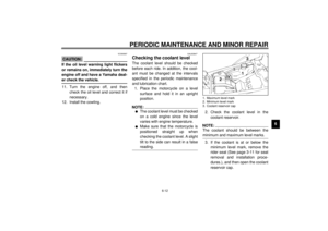 57
57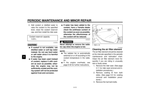 58
58 59
59 60
60 61
61 62
62 63
63 64
64 65
65 66
66 67
67 68
68 69
69 70
70 71
71 72
72 73
73 74
74 75
75 76
76 77
77 78
78 79
79 80
80 81
81 82
82 83
83 84
84 85
85 86
86 87
87 88
88 89
89 90
90 91
91 92
92 93
93 94
94 95
95 96
96 97
97 98
98 99
99 100
100 101
101 102
102 103
103 104
104 105
105 106
106 107
107
