Page 49 of 116

Instrument and control functions
4-27
4
EAU86160
Fuel tank overflow hoseThe overflow hose drains excess gaso-
line and directs it safely away from the
vehicle.
Before operating the vehicle:
Check the fuel tank overflow hose
connection.
Check the fuel tank overflow hose
for cracks or damage, and replace
it if necessary.
Make sure that the fuel tank over-
flow hose is not blocked, and
clean it if necessary.
Make sure that the fuel tank over-
flow hose is positioned as shown.
TIPSee page 7-10 for canister information.
EAU13435
Catalytic converterThe exhaust system contains catalytic
converter(s) to reduce harmful exhaust
emissions.
WARNING
EWA10863
The exhaust system is hot after op-
eration. To prevent a fire hazar d or
b urns:
Do not park the vehicle near
possi ble fire hazar ds such as
g rass or other materials that
easily burn.
Park the vehicle in a place
where pe destrians or child ren
are not likely to touch the hot
exhaust system.
Make sure that the exhaust sys-
tem has coole d down before
d oin g any maintenance work.
Do not allow the en gine to i dle
more than a few minutes. Lon g
i d lin g can cause a b uild-up of
heat.
1. Fuel tank overflow hose
2. Original position (paint mark)
3. Clamp
11133
22
UBAPE0E0.book Page 27 Thursday, December 24, 2020 9:14 AM
Page 50 of 116

Instrument and control functions
4-28
4
EAU92640
SeatsPassen ger seat
To remove the passenger seat1. Insert the key into the seat lock, and then turn it counterclockwise.
2. Lift the front of the passenger seat and pull it forward.
To install the passenger seat1. Insert the projections on the rear of the passenger seat into the seat
holders as shown, and then push
the front of the seat down to lock
it in place. 2. Remove the key.
Ri der seat
To remove the rider seat
1. Remove the passenger seat.
2. Remove the cap, then push the rider seat lock lever, located under
the back of the rider seat, to the
left as shown, and then pull the
seat off. To install the rider seat
1. Insert the projection on the front of
the rider seat into the seat holder
as shown, and then push the rear
of the seat down to lock it in place.
1. Seat lock
2. Unlock.
1 1 1
2
2
1. Projection
2. Seat holder
1
2
1. Cap
2. Rider seat lock lever
1. Projection
2. Seat holder
2
1 1 11 1 1
2 2
UBAPE0E0.book Page 28 Thursday, December 24, 2020 9:14 AM
Page 51 of 116
Instrument and control functions
4-29
4
2. Install the cap.
3. Install the passenger seat.
TIP
Make sure that the seats are prop-
erly secured before riding.
The rider seat height can be ad-
justed. See the following section.
EAU92633
Adjustin g the ri der seat hei ghtThe rider seat height can be adjusted
to one of two positions.
To chan ge to the hi gh position
1. Remove the passenger seat and rider seat.
2. Remove the rider seat height posi- tion adjuster by pulling it upward. 3. Install the rider seat height posi-
tion adjuster by inserting the front
projections into the grommets.
4. Remove the rubber cover.
1. Cap
1 1 1
1. Low position
2. High position
1
2
1. Rider seat height position adjuster
1. Rider seat height position adjuster
2. Projection
3. Grommet
1 1 1
11 1
2 2 2
2 2 2
3 3
UBAPE0E0.book Page 29 Thursday, December 24, 2020 9:14 AM
Page 52 of 116
Instrument and control functions
4-30
4
TIPDo not lose the rubber cover.5. Insert the projection on the front of
the rider seat into seat holder B as
shown. 6. Align the projection on the bottom
of the rider seat with the “H” posi-
tion slot, and then push the rear of
the seat down to lock it in place as
shown.
7. Install the passenger seat.
To chan ge to the low position
1. Remove the passenger seat and rider seat.
2. Remove the rider seat height posi- tion adjuster by pulling it upward.
3. Install the rider seat height posi- tion adjuster by inserting the rear
projections into the grommets. 4. Install the rubber cover.
TIPInsert the projections in order from a to
d.
1. Rubber cover
1. Projection
2. Seat holder B (for high position)
1 1 1
2 2 2
1
2
1
2
1. Projection
2.
1 1
2
12
1. Rider seat height position adjuster
2. Projection
3. Grommet
1. Rubber cover
1 1 1
2 2
2 2
3 3
d
c
b a
1
UBAPE0E0.book Page 30 Thursday, December 24, 2020 9:14 AM
Page 53 of 116
Instrument and control functions
4-31
4
5. Insert the projection on the front of
the rider seat into seat holder A as
shown.
6. Align the projection on the bottom of the rider seat with the “L” posi-
tion slot, and then push the rear of
the seat down to lock it in place as
shown. 7. Install the passenger seat.
TIPMake sure that the seats are properly
secured before riding.
EAU91560
Ri
der footrest positionThe rider footrests can be adjusted to
one of two positions. From the factory,
the footrests are in the low position.
Have a Yamaha dealer adjust the posi-
tions of the rider footrests.
1. Projection
2. Seat holder A (for low position)
1 1
2
2
1
22
1. Projection
2.
1 1
2 12
UBAPE0E0.book Page 31 Thursday, December 24, 2020 9:14 AM
Page 54 of 116

When storing documents or other
items in the storage")
Instrument and control functions
4-32
4
EAU62550
Stora ge compartmentThe storage compartment is located
under the passenger seat. (See page
4-28.)
When storing documents or other
items in the storage compartment, be
sure to wrap them in a plastic bag so
that they will not get wet. When wash-
ing the vehicle, be careful not to let any
water enter the storage compartment.
WARNING
EWA15401
Do not exceed the maximum loa d of
193 k g (425 lb ) for the vehicle.
EAU83932
Windshield This model is equipped with an adjust-
able windshield.
To change the position of the wind-
shield, lift up the windshield lock lever
and slide the windshield up or down.
Release the lock lever when finished.TIPMake sure the windshield and lock le-
ver are properly secured before riding.
EAU46833
Handle bar position The handlebar can be adjusted to one
of two positions to suit the rider’s pref-
erence. Have a Yamaha dealer adjust
the position of the handlebar.
1. Storage compartment
1 1 1
1. Windshield lock lever
2. Windshield
111
2
1. Handlebar
1
UBAPE0E0.book Page 32 Thursday, December 24, 2020 9:14 AM
Page 55 of 116
. See pages 3-4")
Instrument and control functions
4-33
4
EAU92782
A djustin g the front an d rear
suspensionThis model is equipped with an elec-
tronically controlled suspension damp-
ing system (KADS). See pages 3-4,
4-13 for more information on KADS
and SUS-MODE.TIPAfter any service to the rear suspen-
sion, a sensor calibration must be per-
formed via the settings MENU. See
page 4-21 for more information on
SUS. Sensor Calibration.Sprin g preloa d of the front fork
WARNING
EWA10181
Always a djust both fork le gs equally,
otherwise poor han dlin g an d loss of
sta bility may result.NOTICE
ECA27260
Use extra care to avoi d scratching
the anod ized finish when makin g
suspension a djustments.
Turn the adjusting nut in direction (a) to
increase the spring preload.
Turn the adjusting nut in direction (b) to
decrease the spring preload.
To set the spring preload, turn the ad-
juster in direction (b) until it stops, and
then count the turns in direction (a). Sprin
g preloa d of the shock a bsor b-
er assem bly
WARNING
EWA10222
This shock a bsor ber assem bly con-
tains hig hly pressurize d nitro gen
g as. Rea d an d un derstan d the fol-
lowin g information before han dlin g
the shock a bsor ber assem bly.
Do not tamper with or attempt
to open the cylind er assembly.
Do not su bject the shock a b-
sor ber assem bly to an open
flame or other hi gh heat source.
This may cause the unit to ex-
plo de due to excessive gas
pressure.
Do not deform or damag e the
cylin der in any way. Cylin der
d ama ge will result in poor
d ampin g performance.
Do not dispose of a d amaged or
worn-out shock a bsor ber as-
sem bly yo
u
rself. Take the shock
a b sor ber assem bly to a Yamaha
d ealer for any service.
Turn the adjusting knob in direction (a)
to increase the spring preload.
1. Spring preload adjusting nut
Sprin g preloa d settin g:
Minimum (soft): 0 turn(s) in direction (a)
Standard: 2 turn(s) in direction (a)
Maximum (hard):
10 turn(s) in direction (a)
1 11
11
11(a) (a) (a)
(b) (b) (b)
UBAPE0E0.book Page 33 Thursday, December 24, 2020 9:14 AM
Page 56 of 116

to decrease the spring preload.
To set the spring preload, turn the ad-
juster in direction (b) until it stops, and
the")
Instrument and control functions
4-34
4 Turn the adjusting knob in direction (b)
to decrease the spring preload.
To set the spring preload, turn the ad-
juster in direction (b) until it stops, and
then count the clicks in direction (a).
TIPWhen turning the spring preload ad-
juster in direction (b), the 0 click posi-
tion and the 1 click position may be the
same.
EAU84680
Lugga
ge strap hol dersUse the indicated strap points to se-
cure luggage ties to the vehicle.
EAU49454
Auxiliary DC jackA 12-V accessory connected to the
auxiliary DC jack can be used when the
main switch is on.NOTICE
ECA15432
The accessory connecte d to the
auxiliary DC jack shoul d not b e used
with the en gine turne d off, an d the
loa d must never excee d 24 W (2 A),
otherwise the fuse may blow or the
b attery may d ischarge.To use the auxiliary DC jack
1. Turn the main switch off.
2. Remove the auxiliary DC jack cap.
3. Turn the accessory off.
1. Spring preload adjusting knobSprin g preloa d setting :
Minimum (soft): 1 click(s) in direction (a)
Standard: 11 click(s) in direction (a)
Maximum (hard):
24 click(s) in direction (a)
(a) (a) (a)
(b) (b) (b) 1
1. Luggage strap holder
1 1 1
1. Auxiliary DC jack cap
1 1 1
UBAPE0E0.book Page 34 Thursday, December 24, 2020 9:14 AM
 1
1 2
2 3
3 4
4 5
5 6
6 7
7 8
8 9
9 10
10 11
11 12
12 13
13 14
14 15
15 16
16 17
17 18
18 19
19 20
20 21
21 22
22 23
23 24
24 25
25 26
26 27
27 28
28 29
29 30
30 31
31 32
32 33
33 34
34 35
35 36
36 37
37 38
38 39
39 40
40 41
41 42
42 43
43 44
44 45
45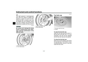 46
46 47
47 48
48 49
49 50
50 51
51 52
52 53
53 54
54 55
55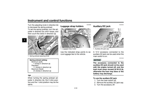 56
56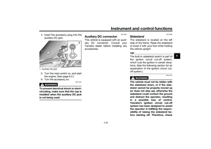 57
57 58
58 59
59 60
60 61
61 62
62 63
63 64
64 65
65 66
66 67
67 68
68 69
69 70
70 71
71 72
72 73
73 74
74 75
75 76
76 77
77 78
78 79
79 80
80 81
81 82
82 83
83 84
84 85
85 86
86 87
87 88
88 89
89 90
90 91
91 92
92 93
93 94
94 95
95 96
96 97
97 98
98 99
99 100
100 101
101 102
102 103
103 104
104 105
105 106
106 107
107 108
108 109
109 110
110 111
111 112
112 113
113 114
114 115
115

