Page 33 of 98

Control function operation
26
zle is changed, and the direction of the water-
craft is changed accordingly.
Since the strength of the jet thrust determines
the speed and degree of a turn, throttle must
always be applied when attempting a turn,
except at trolling speed.
This model is equipped with the Yamaha En-
gine Management System (YEMS) that in-
cludes an off-throttle steering (OTS) system.
It will activate at planing speeds should you
attempt to steer the watercraft after releasing
the throttle lever. The OTS system assists in
turning by continuing to supply some thrust
while the watercraft is decelerating, but you
can turn more sharply if you apply throttle
while turning the handlebars. The OTS sys-
tem does not function below planing speeds
or when the engine is off. Once the engine
slows down, the watercraft will no longer turn
in response to handlebar input until you apply
throttle again or you reach trolling speed.EJU35975Cooling water pilot outlet
When the engine is running, some of the
cooling water that is circulated in the engine
is discharged from the cooling water pilot
outlet.
There is a cooling water pilot outlet on the
port (left) side of the watercraft. To check for
proper operation of the cooling system, make
sure that water is being discharged from the
cooling water pilot outlet. If water is not being
discharged from the outlet, stop the engine
and check the jet intake for clogging. (See
page 85 for information on the jet intake.)
TIP:
It will take about 60 seconds for the water
to reach the outlet after the engine is start-
ed.
Water discharge may not be constant
when the engine is running at idling speed.
If this occurs, apply a little throttle to make
sure that water discharges properly.
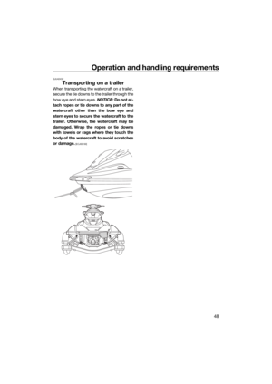
EJU40323Water separator
The water separator prevents water from en-
tering the fuel tank by collecting any water
that has entered the fuel tank breather hose if
the watercraft was capsized.
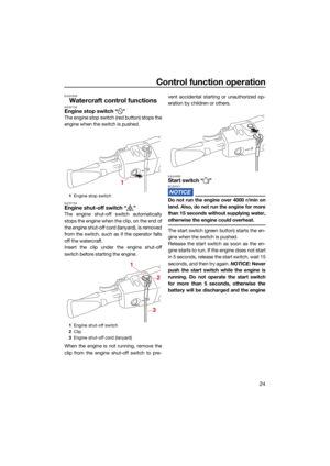
1Handlebar
2 Jet thrust nozzle
1
21Cooling water pilot outlet
1
UF4L72E0.book Page 26 Thursday, June 18, 2020 1:29 PM
Page 34 of 98
Control function operation
27
If water has collected in the water separator,
drain it by loosening the drain screw.
To drain water from the water separator:
(1) Place a drain pan or dry cloth under thewater separator.
(2) Gradually loosen the drain screw to drain the water. Catch the draining water in the
drain pan or soak it up with the dry cloth
so that it does not spill into the engine
compartment. If any water spills into the
watercraft, be sure to wipe it up with a
dry cloth.
(3) Securely tighten the drain screw until it stops.
1Water separator
2 Drain screw
2
1
UF4L72E0.book Page 27 Thursday, June 18, 2020 1:29 PM
Page 35 of 98

Watercraft operation
28
EJU40014
Watercraft operation functions
EJU43154Shift system EWJ01773
Make sure that there are no obstacles or
people behind you before shifting into
reverse.
Do not touch the reverse gate while the
RiDE lever is being operated, otherwise
you could be pinched.
If the RiDE lever and throttle lever are
being operated at the same time, do not
release only the RiDE lever. Otherwise,
the watercraft could accelerate more
quickly than expected, which may lead
to an accident.
The RiDE lever and throttle lever can be oper-
ated to change the forward or rearward
movement of the watercraft only when the
engine is running. When the RiDE lever is
squeezed, the reverse gate lowers and de-
flects the water jet being discharged from the
jet thrust nozzle so that the watercraft moves
in reverse or is in neutral. When the throttle le-
ver is squeezed, the reverse gate rises and
the watercraft moves forward.
TIP:
This model is equipped with a function
which limits the engine speed in reverse.
When the engine is started, the reverse
gate automatically moves to the neutral po-
sition.
To shift into reverse:
(1) Release the throttle lever.
(2) Squeeze the RiDE lever. The reverse gate will lower, the engine speed will in-
crease, the watercraft will start moving in reverse, and the “R” (reverse) shift indi-
cator will be displayed.
To shift into neutral from reverse:
Release the RiDE lever. The reverse gate will
automatically return to the neutral position
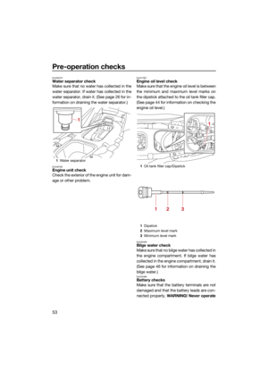
1 RiDE lever
1 Reverse gate
2 Reverse position
1 “R” (Reverse position)
1
1
2
1
UF4L72E0.book Page 28 Thursday, June 18, 2020 1:29 PM
Page 36 of 98
Watercraft operation
29
and the “N” (neutral) shift indicator will be dis-
played.
TIP:
Although the neutral position helps keep the
watercraft from moving even when the en-
gine is running, some movement may occur.To shift into forward:
(1) Release the RiDE lever.
(2) Squeeze the throttle lever. The reverse
gate will rise completely, the engine
speed will increase, the watercraft will
start moving forward, and the “F” (for-
ward) shift indicator will be displayed.
1RiDE lever
1 Reverse gate
2 Neutral position
1 “N” (Neutral position)
1
1
2
1
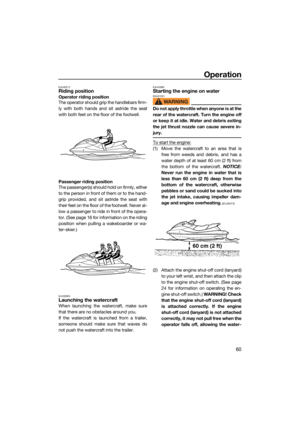
1Throttle lever
1 Reverse gate
2 Forward position
1 “F” (Forward position)
1
1
2
1
UF4L72E0.book Page 29 Thursday, June 18, 2020 1:29 PM
Page 37 of 98
Watercraft operation
30
TIP:
If the RiDE lever is squeezed while the throttle
lever is squeezed, the watercraft will slow
down, and once stopped, move in reverse.
To shift into neutral from forward:
(1) Release the throttle lever.
(2) Lightly squeeze and release the RiDE le-ver. The “N” (neutral) shift indicator will
be displayed.
TIP:
If the RiDE lever is squeezed continuously,
the reverse gate will move to the reverse po-
sition.
1“N” (Neutral position)
1
UF4L72E0.book Page 30 Thursday, June 18, 2020 1:29 PM
Page 38 of 98

Instrument operation
31
EJU44570
Multifunction information center
The multifunction information center displays
various watercraft information.
Multifunction information center initial op-
eration
When the multifunction information center is
activated, all of the display segments come
on. After 2 seconds, the warning indicators in
the information display go off, and then the
center starts to operate normally.
Multifunction information center standby
state
If the multifunction information center does
not receive any operation input within 30 sec-
onds after the engine stops, the center will
turn off and enter a standby state. When the
engine is started again, the displays return to
their state before the center turned off, and
then the center starts to operate normally.
EJU35027Information display
The information display shows watercraft op-
erating conditions.
EJU43832Speedometer
The speedometer shows the watercraft
speed against water.
By switching the display units, the speed can
be shown in kilometers per hour “km/h” or
miles per hour “MPH”.
TIP:
“MPH” is selected as the display unit at the
Yamaha factory.
1 Information display
2 “WARNING” indicator light
12
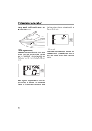
1Fuel level meter
2 Shift indicator
3 Engine overheat warning indicator
4 Check engine warning indicator
5 Tachometer / hour meter / voltmeter
6 Oil pressure warning indicator
7 Fuel level warning indicator
8 Speedometer
1 Speedometer
251346
78
1
UF4L72E0.book Page 31 Thursday, June 18, 2020 1:29 PM
Page 39 of 98

Instrument operation
32
To switch the speedometer display units:
Start the engine, stop the engine, and then
push the engine stop switch 3 times, pushing
the switch for 0.4 seconds or more each time,
before the multifunction information center
turns off. The speedometer display units
change.
To switch the speedometer display units
again, repeat this procedure.
EJU44650Tachometer
The tachometer shows the engine speed.
TIP:
While the engine is stopped, the battery volt-
age and the total engine hours are displayed
alternately.
EJU43891Shift indicator
This indicator shows the reverse gate shift
positions: “F” (forward), “N” (neutral), and “R”
(reverse). (See page 28 for shifting proce-
dures.)
EJU44700Hour meter and voltmeter
The hour meter and voltmeter are displayed
in the tachometer portion of the information
display while the engine is stopped.
1 Engine stop switch
1 Speedometer
1
1
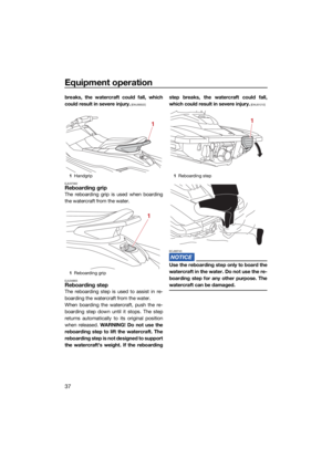
1Tachometer
1 Shift indicator
2 “F” (Forward position)
3 “N” (Neutral position)
4 “R” (Reverse position)
1
12
3
4
UF4L72E0.book Page 32 Thursday, June 18, 2020 1:29 PM
Page 40 of 98

Instrument operation
33
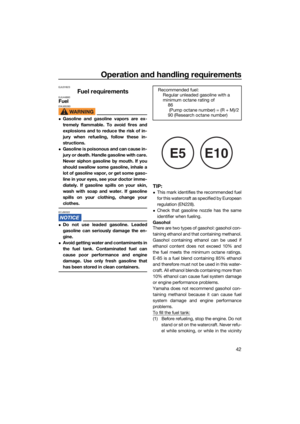
The hour meter and voltmeter are displayed
alternately at 3-second intervals.
TIP:
If the engine is stopped after the check en-
gine warning is activated, the hour meter and
error code will be displayed alternately at 3-
second intervals.
Hour meter
The hour meter shows the total number of
hours that the engine has been running since
the watercraft was new.
TIP:
The elapsed time will be kept even if the bat-
tery terminals have been disconnected.
Voltmeter
The voltmeter shows the battery voltage.
When the battery voltage is normal, the volt-
meter displays approximately 12 volts.If the battery voltage has dropped significant-
ly, “Lo” is displayed on the voltmeter, and all
other display segments of the information
display turn off. If the battery voltage has ris-
en significantly, “HI” is displayed. If “Lo” or
“HI” is displayed, immediately return to shore
and have a Yamaha dealer service the water-
craft.
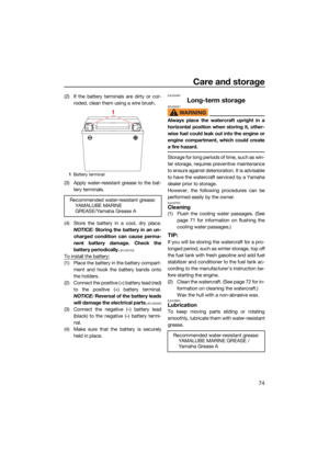
EJU37272Fuel level meter
The fuel level meter shows the amount of fuel
remaining in the fuel tank. The amount of re-
maining fuel is shown using four display seg-
ments, which disappear one at a time as the
fuel level decreases.
TIP:
The accuracy of the fuel level meter varies
depending on the operating conditions. Use
this function as a reference only.
1
Hour meter and voltmeter
1 Hour meter
1
1
1Vo l t m et e r
1 Fuel level meter
1
1
UF4L72E0.book Page 33 Thursday, June 18, 2020 1:29 PM


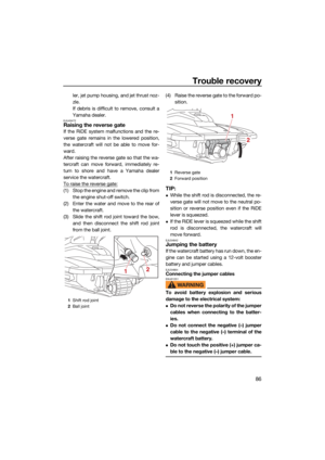


 Place a drain pan or dry cloth under th")
 shift indicator will be dis-
played.
TIP:
Although the neutral position helps keep the
watercraft from moving even when the en-
gine is running, some")
