2021 VOLVO V90 CROSS COUNTRY height
[x] Cancel search: heightPage 272 of 683
||
KEY, LOCKS AND ALARM
* Option/accessory.
270
Interrupting closing
Press the button on the dashboard.
Press the button on the remote key.
Press the close button on the underside of the tailgate 13
.
Press the rubberized pressure plate on the underside of the tailgate's outer handle.
Using a foot movement
*.
Tailgate movement is interrupted and stops.The tailgate can then be opened or closedmanually. If the tailgate stops near the closed position, it will open the next time it is activated.
Pinch protectionIf anything obstructs the tailgate with enoughforce to prevent it from opening or closing,pinch protection will be activated.
When opening - the tailgate will stopmoving and an audible signal will sound.
When closing - the tailgate will stop, along audible signal will sound and the tail-gate will return to the programmed maxi-mum opening position.
WARNING
Be aware of the risk of injury when opening and closing. Before opening or closing, make sure that no one is near the tailgate's range ofmotion. Serious injury could occur. Always operate the tailgate with caution.
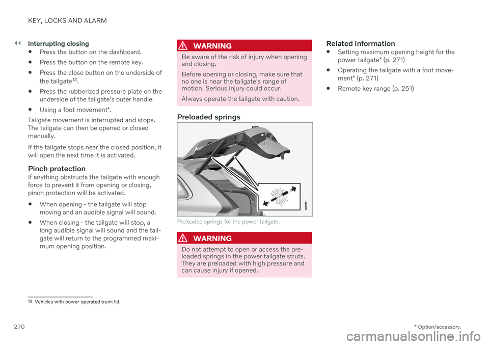
Preloaded springs
Preloaded springs for the power tailgate.
WARNING
Do not attempt to open or access the pre- loaded springs in the power tailgate struts.They are preloaded with high pressure andcan cause injury if opened.
Related information
Setting maximum opening height for the power tailgate
* (p. 271)
Operating the tailgate with a foot move-ment
* (p. 271)
Remote key range (p. 251)
13
Vehicles with power-operated trunk lid.
Page 273 of 683

KEY, LOCKS AND ALARM
}}
* Option/accessory.271
Setting maximum opening height for the power tailgate *
The tailgate can be set to stop opening at a certain height, for example if the tailgateneeds to be opened in a garage with a lowceiling.
Setting maximum opening height1. Open the tailgate manually to the desired opening height.
2. Press the
button on the lower edge of
the tailgate and hold it for about 3 seconds.
> Two audio signals will sound to indicate that the position has been stored.
NOTE
It is not possible to program an opening position lower than half-open tailgate.
Resetting maximum opening position1. Open the tailgate manually to the fully open position.
2. Press the
button on the lower edge of
the tailgate and hold it for about 3 seconds.
> Two audio signals will sound to indicate that the stored position has been erased.
NOTE
If the system has been working contin- uously for a prolonged period of time, itwill be switched off to avoid overload.It can be used again after approxi-mately 2 minutes.
Operating the tailgate with a foot movement
*
To make it easier to operate the tailgate when your hands are full, it can be opened andclosed by moving your foot in a forward kick-ing motion under the rear bumper.
The sensor is located to the left of center under the rear bumper.
One of the vehicle's remote keys must be within range behind the vehicle, approx.1 meter (3 feet), for opening and closing to bepossible. This applies even if the vehicle isunlocked in order to prevent the trunk lid frominadvertently opening e.g. at a car wash.
Page 343 of 683

DRIVER SUPPORT
}}
341
City Safety limitationsCity Safety 81
functionality may be reduced in
certain situations.
Surroundings
Low objects
Hanging objects, such as flags for overhang- ing loads or accessories such as auxiliarylights or front protective grids that extendbeyond the height of the hood, may limit City Safety functionality.
Slippery road conditions
The extended braking distance on slippery roads may reduce City Safety's capacity tohelp avoid a collision. In these types of situa-tions, the Anti-lock Braking System and Elec- tronic Stability Control (ESC 82
) are designed
for optimal braking power with maintained stability.
Backlighting
The visual warning signal in the windshield may be difficult to detect in bright sunlight, ifthere are reflections, or if the driver is wearingsunglasses or not looking straight ahead.
Heat
If the temperature in the passenger compart- ment is high due to e.g. bright sunlight, thevisual warning signal in the windshield may betemporarily disabled.
Camera and radar sensor's field of vision
The camera's field of vision is limited and in certain situations, it may be unable to detectpedestrians, large animals, cyclists or vehicles,or it may detect them later than expected. Vehicles that are dirty may be detected later than clean vehicles, and in dark conditions,motorcycles may be detected late or not at all. If a text message displayed in the instrument panel indicates that the camera or radar sen-sor is obstructed, it may be difficult for CitySafety to detect pedestrians, large animals,cyclists, vehicles or lane markings in front ofthe vehicle. City Safety functionality maytherefore be reduced. Text messages may not be displayed for all sit- uations in which the windshield sensors areblocked. The driver must therefore alwayskeep the windshield in front of the camera/radar sensor clean.
CAUTION
Only a workshop may perform mainte- nance on driver support components – anauthorized Volvo workshop is recom-mended.
Driver intervention
Backing up
City Safety is temporarily deactivated when the vehicle is backing up.
Low speed
City Safety is not activated at very low speeds under 4 km/h (3 mph). The system will there-fore not intervene in situations in which yourvehicle is approaching another vehicle veryslowly, such as when parking.
Active driver
Action by the driver always has priority. City Safety will therefore not react or will react at alater stage with a warning or intervention insituations in which the driver is clearly steeringand operating the accelerator pedal, even if acollision is unavoidable. An active and aware driving style may there- fore delay collision warnings and interventionin order to minimize unnecessary warnings.
81 This function is not available on all markets.
82 Electronic Stability Control
Page 431 of 683
STARTING AND DRIVING
}}
* Option/accessory.429
Leveling control * and suspension
Self-leveling and suspension functions are controlled automatically.
Rear leveling control keeps the rear section of the vehicle at the same height regardless ofload. Leveling control may also remain activewhen the vehicle is parked.
Shock absorbers (Four-C)On vehicles equipped with Four-C, the shockabsorbers are adapted to the selected drive mode and the current vehicle speed. Theshock absorbers are normally set to help opti-mize comfort and are adjusted continuouslyaccording to the road surface and the vehicle'sacceleration, braking and cornering.
TransportingWhen transporting the vehicle on a ferry, trainor truck, only secure (lash) the vehicle aroundthe tires, not using any other parts of the chas-sis. Changes in the pneumatic suspension
may occur during transport, which couldadversely affect the lashing and result in dam-age.
Symbols and messagesIf a problem occurs with the leveling control, amessage will be displayed in the instrumentpanel.
Symbol Message Meaning
Suspension Deactivated by userActive chassis has been switched off manually by the user.
Suspension Temporarily reduced performanceActive chassis performance has been temporarily reduced due to extensive system use.
Page 432 of 683
||
STARTING AND DRIVING
430
Symbol Message Meaning
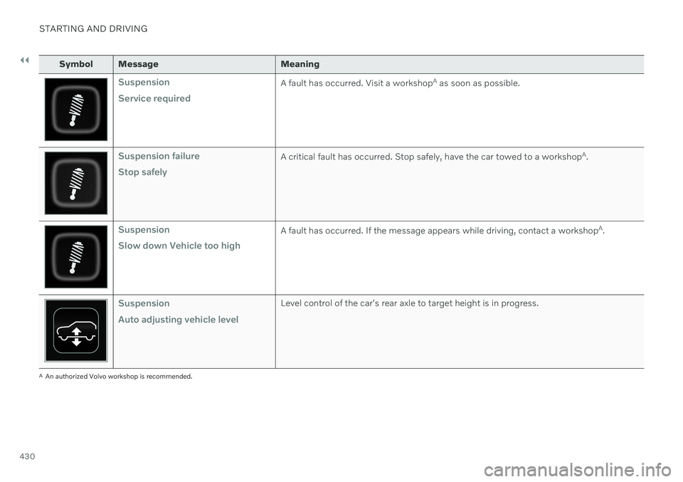
Suspension Service requiredA fault has occurred. Visit a workshopA
as soon as possible.
Suspension failure Stop safelyA critical fault has occurred. Stop safely, have the car towed to a workshop A
.
Suspension Slow down Vehicle too highA fault has occurred. If the message appears while driving, contact a workshop A
.
Suspension Auto adjusting vehicle levelLevel control of the car's rear axle to target height is in progress.
A An authorized Volvo workshop is recommended.
Page 539 of 683
WHEELS AND TIRES
}}
537
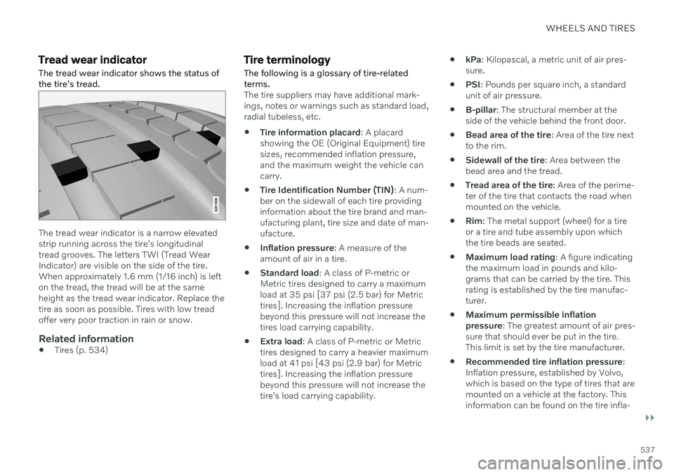
Tread wear indicatorThe tread wear indicator shows the status of the tire's tread.
The tread wear indicator is a narrow elevated strip running across the tire's longitudinaltread grooves. The letters TWI (Tread WearIndicator) are visible on the side of the tire.When approximately 1.6 mm (1/16 inch) is lefton the tread, the tread will be at the sameheight as the tread wear indicator. Replace thetire as soon as possible. Tires with low treadoffer very poor traction in rain or snow.
Related information
Tires (p. 534)
Tire terminology
The following is a glossary of tire-related terms.
The tire suppliers may have additional mark- ings, notes or warnings such as standard load,radial tubeless, etc.
Tire information placard
: A placard
showing the OE (Original Equipment) tiresizes, recommended inflation pressure,and the maximum weight the vehicle cancarry.
Tire Identification Number (TIN)
: A num-
ber on the sidewall of each tire providinginformation about the tire brand and man-ufacturing plant, tire size and date of man-ufacture.
Inflation pressure
: A measure of the
amount of air in a tire.
Standard load
: A class of P-metric or
Metric tires designed to carry a maximumload at 35 psi [37 psi (2.5 bar) for Metrictires]. Increasing the inflation pressurebeyond this pressure will not increase thetires load carrying capability.
Extra load
: A class of P-metric or Metric
tires designed to carry a heavier maximumload at 41 psi [43 psi (2.9 bar) for Metrictires]. Increasing the inflation pressurebeyond this pressure will not increase thetire's load carrying capability.
kPa
: Kilopascal, a metric unit of air pres-
sure.
PSI
: Pounds per square inch, a standard
unit of air pressure.
B-pillar
: The structural member at the
side of the vehicle behind the front door.
Bead area of the tire
: Area of the tire next
to the rim.
Sidewall of the tire
: Area between the
bead area and the tread.
Tread area of the tire
: Area of the perime-
ter of the tire that contacts the road whenmounted on the vehicle.
Rim
: The metal support (wheel) for a tire
or a tire and tube assembly upon whichthe tire beads are seated.
Maximum load rating
: A figure indicating
the maximum load in pounds and kilo-grams that can be carried by the tire. Thisrating is established by the tire manufac-turer.
Maximum permissible inflationpressure
: The greatest amount of air pres-
sure that should ever be put in the tire.This limit is set by the tire manufacturer.
Recommended tire inflation pressure
:
Inflation pressure, established by Volvo,which is based on the type of tires that aremounted on a vehicle at the factory. Thisinformation can be found on the tire infla-
Page 540 of 683
||
WHEELS AND TIRES
538tion placard(s) located on the driver's side B-pillar and in the tire inflation table.
Cold tires
: The tires are considered to be
cold when they have the same tempera-ture as the surrounding (ambient) air. Thistemperature is normally reached after thevehicle has been parked for at least 3hours.
Related information
Tires (p. 534)
Tire sidewall designations
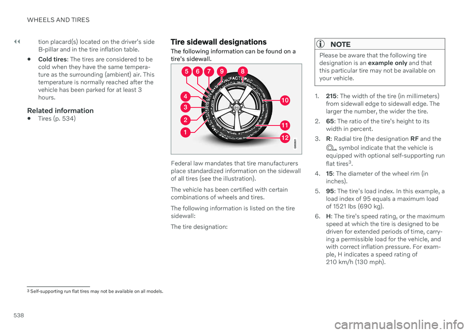
The following information can be found on a tire's sidewall.
Federal law mandates that tire manufacturers place standardized information on the sidewallof all tires (see the illustration). The vehicle has been certified with certain combinations of wheels and tires. The following information is listed on the tire sidewall: The tire designation:
NOTE
Please be aware that the following tire designation is an example only and that
this particular tire may not be available onyour vehicle.
1. 215: The width of the tire (in millimeters)
from sidewall edge to sidewall edge. The larger the number, the wider the tire.
2. 65: The ratio of the tire's height to its
width in percent.
3. R: Radial tire (the designation RF and the
symbol indicate that the vehicle is
equipped with optional self-supporting run flat tires 3
.
4. 15: The diameter of the wheel rim (in
inches).
5. 95: The tire's load index. In this example, a
load index of 95 equals a maximum load of 1521 lbs (690 kg).
6. H: The tire's speed rating, or the maximum
speed at which the tire is designed to bedriven for extended periods of time, carry-ing a permissible load for the vehicle, andwith correct inflation pressure. For exam-ple, H indicates a speed rating of210 km/h (130 mph).
3 Self-supporting run flat tires may not be available on all models.
Page 593 of 683
MAINTENANCE AND SERVICE
* Option/accessory.591
6. Crank it up until it is properly aligned and
it is in contact with the vehicle's jack attachment point. Make sure the top ofthe jack (or the garage lift arms) is cor-rectly positioned in the attachment point,with the bump on the top of the jack in therecess in the attachment point and itsbase positioned vertically under theattachment point.
7. Turn the jack so that the crank is as far as possible from the side of the vehicle,which will position the jack's arms per-pendicular to the vehicle's direction ofmovement.
8. Raise the vehicle to a suitable height for the operation to be performed.
Related information
Jack
* (p. 551)
Wheel bolts (p. 551)
Tool kit (p. 550)
Leveling control settings
* (p. 432)