2021 VOLKSWAGEN TRANSPORTER check engine
[x] Cancel search: check enginePage 158 of 486

Removing the central table
The central table can be removed more easily by two people than by one person.
• Remove front protective covers from the central seat rails.
• Turn the single seats so that they face the di-rection of travel.
• Adjust the back rest of single seats to an upright position.
• Fold up the armrests of the single seats.
• Pull the handle @ up and hold the central table with the handle and the handle recess@.
• Push the central table forwards to the point where it can be lifted out of the slots in the seat rails.
• Lift the central table out.
• Put down the central table carefully so that the rollers and feet are not soiled or damaged.
• Place the removed covers on the open slots in the seat rails.
Fitting the central table
The central table can be installed more easily by two people than by one person.
• Remove front protective covers from the central seat rails.
• Turn the single seats so that they face the di-rection of travel.
Cool box
c:cn Introduction
This chapter contains information on the following subjects:
Fitting and removing the cool box
Switching the cool box on and off 159 161
The cool box may be used while the vehicle is in motion only if it is fitted to the adapter plate.
Power for the cool box can be supplied by any of the 12-volt sockets in the vehicle. The power con-sumption is approx. 33 watts. The cool box has a capacity of 32 litres.
Follow instructions provided for the installation and use of the cool box and keep it in the vehicle wal-let.
As far as possible, keep food and drinks in the cool box in leak-proof containers. Do not overfill the cool box such that air circulation is impaired.
158 Before the journey
• Adjust the backrest of single seats to an upright position.
• Fold up the armrests of the single seats.
• Pull the handle @ up and hold the central table with the handle and the handle recess®.
• Insert the central table guides into the recesses in the seat rails.
• Insert the central table into the seat rails and push them back, so that the removed covers can be placed on the open slots in the seat rails.
• Fold the handle@ back to engage the central table in the seat rails.
• Check that the central table is locked securely. it should now no longer be possible to move the central table.
• Do not raise the table module when the cen-tral table Is located between the single seats. This could cause damage to the table.
The vehicle battery will be drained if the cool box is used when the engine is switched off. For this rea-son, the cool box is fitted with a battery monitor. The battery monitor will switch the cool box off if the vehicle battery has a low charge level. The bat-tery monitor will switch the cool box on again as soon as the battery has reached a suitable charge level, for example, after a long journey.
Additional information and warnings:
• Seat functions, front =>page 69
• Seat functions, rear =>page 72
• Seat functions, rear, Business =>page 182
• Seat functions, rear, California =>page 193
• Electrical sockets =>page 163
• Battery =>page 350
Page 161 of 486
Switching the cool box on and off
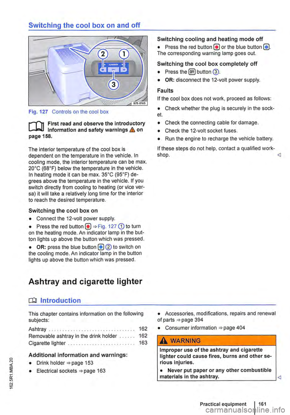
Fig. 127 Controls on the cool box
r-f'n First read and observe the Introductory Information and safety warnings & on page 158.
The interior temperature of the cool box is dependent on the temperature in the vehicle. In cooling mode, the interior temperature can be max. 20•c (68°F) below the temperature in the vehicle. In heating mode it can be max. 35•c (95.F) de-grees above the temperature in the vehicle. If you switch directly from cooling to heating (or vice ver-sa) it will take a relatively long time for the interior to reach the desired temperature.
Switching the cool box on
• Connect the 12-volt power supply.
• Press the red Fig. 127 G) to turn on the heating mode. An indicator lamp in the but-ton lights up above the button which was pressed.
• OR: press the blue button (!)®to switch on the cooling mode. An indicator lamp in the button lights up above the button which was pressed.
Ashtray and cigarette lighter
o:n Introduction
This chapter contains information on the following subjects:
Ashtray . . . . . . . . . . . . . . . . . . . 162
Removable ashtray in the drink holder 162
Cigarette lighter . . . . . . . . . . . . . . . . . . . 163
Additional information and warnings:
• Drink holder 153
• Electrical sockets 163
Switching cooling and heating mode off
• Press the red button(!) or the blue button (!). The corresponding warning lamp goes out.
Switching the cool box completely off
• Press the@) button @.
• OR: disconnect the 12-volt power supply.
Faults
If the cool box does not work, proceed as follows:
• Check whether the plug is securely in the sock-et.
• Check the connecting cable for damage.
• Check the 12-volt socket fuses.
• Run the engine to recharge the vehicle battery.
If these steps do not help, contact a qualified work-shop.
• Consumer information 404
A WARNING
Improper use of the ashtray and cigarette lighter could cause fires, burns and other se-rious Injuries.
• Never put paper or any other combustible materials In the ashtray.
Page 206 of 486
Symbol Meaning
A Flow of electric current in amps
Lit up: 230-volt mains connection has been made and the battery charger is working. Flashing or displaying a number over 15 volts: malfunction. Disconnect the 230-volt mains connection and have the electrical system checked by a qualified workshop. Not lit up despite a 230-volt connection being made: there is a power cut or malfunction in the battery charger.
G The batteries are being charged by the alternator.
Warning messages
Under certain conditions, such as when the pop-up roof is open, warning messages appear on the dis-play when the engine is started. These warn against possible vehicle or equipment damage.
• Switch off the ignition and correct the cause of the warning message.
Malfunction
If a symbol flashes, there is a fault in the indicated system.
• Press the button G?) for five seconds to clear the fault. If this does not work or if other faults ap-pear, please contact a qualified workshop. Volks-wagen Commercial Vehicles recommends using a Volkswagen Commercial Vehicles dealership for this purpose.
A WARNING
Failure to observe illuminated warning lamps and text messages can lead to your vehicle breaking down in traffic, and can cause acci-dent and serious injury.
A WARNING (Continued)
• Never Ignore any Illuminated warning lamps or text messages.
• Stop the vehicle as soon as possible and when safe to do so.
• Stop the vehicle at a safe distance away from moving traffic and ensure that no part of the exhaust system can come Into contact with any Inflammable material underneath the vehicle, e.g. dry grass or fuel.
• Any broken-down vehicle poses an In-creased accident risk both for you and for other road users. If the situation requires, switch on the hazard warning lights and set up the warning triangle as a warning to other road users.
• Before opening the bonnet, switch off the engine and allow it to cool down sufficiently.
• The engine compartment of any motor ve-hicle is a dangerous area. Serious injuries can be sustained here 350.
CD
Failure to observe illuminated indicator lamps and text messages can lead to your vehicle be-ing damaged.
J'"'""'('n First read and observe the introductory L-J,:.IJ information given on page 204.
Main menu Possible functions
Pop-up roof Opening
Closing
Displays Outside temperature
206 Before the journey
Using the menus
• Turn the rotary/push knob 168@ to highlight a function or submenu or to change a set-ting.
• Press the rotary/push knob to select a function or submenu or to confirm a setting.
Description of the submenu with examples
Open the pop-up roof .,1
Close the pop-up roof .,t
Current outside temperature (28.SO C) ...
Page 223 of 486
Closing the electric pop-up roof
j'"'('n First read and observe the introductory information and safety warnings & on page 221.
• Close all of the windows in the pop-up roof can-vas.
• Remove the children's safety net.
• Lower the bed panel.
• Ensure that the roller shutter is and stays open.
• Make sure that no people or objects, such as blankets or pillows, are on the upper bed. Position the mattress correctly.
• Disconnect any connected devices from the 12-volt socket in the roof frame, and stow them in a safe place in the vehicle.
• Switch on the ignition.
• Open one of the vehicle doors to allow excess air pressure to escape.
• Switch on the central control panel.
• Select the menu option Pop-up roof in the central control panel.
• Select menu option Close (dark background).
• Press and hold the rotary/push knob for ap-proximately four seconds. An acoustic signal is giv-en and the display reads for approximately four seconds Roof bed down? Shutter open? Window open?. All control elements for the pop-up roof are blocked during this safety check.
• Press and hold the rotary/push knob again to continue closing. Make sure that the canvas is not pinched at the front or on the side between the ve-hicle and the roof or the rods.
• Press and hold the rotary/push knob until the hydraulic motor has switched off automatically and the pop-up roof has closed fully. This is shown by the .t symbol in the display. The hydraulic motor has a run-on time of approx. 5 seconds to bleed the hydraulic system.
• Close the roller shutter. Make sure that the can-vas is not pinched.
m The LED lights in the pop-up roof are switch-L!..J ed off automatically as soon as the engine is
Equipment, California I 223
Page 254 of 486

Cleaning the cooker and sink
Clean the surfaces of the gas cooker and sink with commercially available non-abrasive cleaning Remove the pan supports from atop the burners to clean the surface of the gas cooker.
When cleaning the gas cooker, make sure that you do not damage or bend the heat sensors on the burners.
The gas burners should be cleaned with a brush at regular intervals.
CD
Abrasive sponges and cleaning agents can scratch and otherwise damage surfaces.
CD
Cleaning products that contain solvents, e.g. acetone, paint thinner, attack the material and can cause damage. <1
Cleaning the display of the central control panel
CD r-l'n First read and observe the Introductory L-l.::JJ information given on page 252. Do not use solvents such as turpentine or pet-
When cleaning the display, use an anti-static cloth or anti-static agent in order to prevent the build up of static charge on the display, which could render the display symbols unrecognizable
rol to clean the display, as these will damage lt.
[]J First read and observe the introductory information given on page 252.
Fault Possible cause Solution
Supplementary 1. The fuel tank is empty. 1. Fill up with fuel. heating system is malfunctioning or not working at all
2. There is a defective fuse 2. Replace the fuse 249. 429 and 249.
3. The warm air vent is blocked. 3. Remove objects blocking the air intake or warm air vents.
4. Battery voltage too low. 4. Charge the battery using the battery charger or by running the engine.
5. The switch-on time is not program-5. Properly program the switch-on time. med or is incorrectly programmed.
6. The central control panel is not 6. Switch on the central control panel. switched on.
1. Electrical consumers have been 1. Charge the battery using the battery Battery voltage switched on and caused the voltage of charger or by running the engine. too low the additional battery to drop to 10.5 volts or below.
2. The battery charger is malfunction-2. Check the residual current circuit breaker ing. or have the battery charger checked by a qualified workshop.
Battery charger is 1. There is a defective fuse 1. Replace fuse =>page 249. not charging the 429 and 249. battery.
254 Before the journey
Page 255 of 486
Fault Possible cause Solution
2. The feed plug is not connected prop-2. Check the connection between the vehi-erly. cle and the mains.
3. Mains power failure. 3. Inform the electricity company if necessa-ry.
4. The residual current circuit breaker 4. Switch the residual current circuit breaker has tripped. back on.
Problem with the 1. The waste water tank is full. 1. Drain the waste water tank in a suitable waste water sys-location. tem
2. The water level sensor for the waste 2. Have the water level sensor checked by a water tank is malfunctioning. qualified workshop.
Problem with the 1. The fresh water tank is empty. 1. Fill the fresh water tank. fresh water sys-tem
2. The water level sensor for the fresh 2. Have the water level sensor checked by a water tank is malfunctioning. qualified workshop.
Refrigerator box 1. There is a defective fuse 1. Replace fuse 249. does not cool. 429 and 249.
2. Battery voltage too low. 2. Charge the battery using the battery charger or by running the engine.
3. The central control panel is not 3. Switch on the central control panel. switched on.
The electric pop-1. The central control panel is not 1. Switch on the central control panel. up roof does not switched on. open or close or does not open or close fully.
2. The ignition is not switched on. 2 Switching on the ignition
3. The overheating protection on the 3. Wait a few minutes before you attempt to hydraulic pump is activated. open or close the pop-up roof.
4. Battery voltage too low. 4. Charge the battery using the battery charger or by running the engine.
5. There is a defective fuse 5. Replace fuse 249. 429 and 249.
6. There is a temporary malfunction. 6. Press the button for 5 seconds.
7. The electrical system for the pop-up 7. Close the electric pop-up roof manually roof is malfunctioning. 221 and have the electrical system checked by a qualified workshop.
8. The child proof lock has been activa-8. Wait at least 7 minutes before you again led due to the electric pop-up roof hav-attempt to open or close the electric pop-up ing been opened and closed repeatedly roof. within a short period of time.
Technical data, living area
cu First read and observe the Introductory information given on page 252.
Supplementary heating system
I
Maximum heating output: 2.5 kW
Fuel consumption: 0.3 lfh
Equipment, California I 255
<3
Page 262 of 486
Flashes Possible cause Solution
The lock button in the selector lever is not Engage the selector lever lock 265. engaged. The vehicle cannot drive off.
Dual clutch gearbox DSG®. Drive to the nearest qualified workshop immedi-
/ ./ flashes alternately with selector lever dis-ately at a low engine speed to have the system play, e.g. D.
Several warning and indicator lamps will light up briefly as a functional check when the ignition is switched on. They will go out after a few seconds.
A WARNING
Failure to observe illuminated warning lamps and text messages can lead to your vehicle breaking down in traffic, and can cause acci-dent and serious injury.
• Never ignore any illuminated warning lamps or text messages.
Pedals
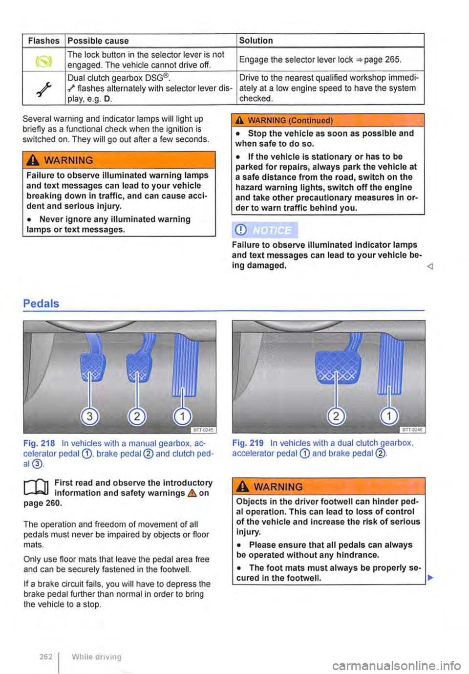
Fig. 218 In vehicles with a manual gearbox, ac-celerator pedal G), brake pedal@ and clutch ped-al@.
r-T'n First read and observe the introductory L-Wl information and safety warnings & on page 260.
The operation and freedom of movement of all pedals must never be impaired by objects or floor mats.
Only use floor mats that leave the pedal area free and can be securely fastened in the footwell.
If a brake circuit fails, you will have to depress the brake pedal further than normal in order to bring the vehicle to a stop.
262 I While driving
checked.
A WARNING (Continued)
• Stop the vehicle as soon as possible and when safe to do so.
• If the vehicle is stationary or has to be parked for repairs, always park the vehicle at a safe distance from the road, switch on the hazard warning lights, switch off the engine and take other precautionary measures In or-der to warn traffic behind you.
CD
Failure to observe Illuminated indicator lamps and text messages can lead to your vehicle be-Ing damaged.
A wARNING
Objects in the driver footwell can hinder ped-al operation. This can lead to loss of control of the vehicle and increase the risk of serious Injury.
• Please ensure that all pedals can always be operated without any hindrance.
• The foot mats must always be properly se-cured in the footwell. .,.
Page 264 of 486
Dual clutch gearbox DSG®
r-('n First read and observe the Introductory L-.lo:on Information and safety warnings & on page 260.
Description
The DSG® dual clutch gearbox is a gearbox which uses dual-clutch technology to change gear automatically. it uses a dual clutch and two independent gearboxes to enable very fast gear changes with no loss of torque. The DSG® dual clutch gearbox thus combines the performance and economy of a manual gearbox with the com-fort and convenience of a conventional automatic transmission.
How the system works
Engine power is transferred to the drive shafts via the gearbox. In order to change gears, the power transmission between the engine and the gearbox has to be interrupted. This is what the clutch is for.
With the DSG® dual clutch system with its two complementary gearboxes, one gearbox is always connected under load to the engine. When one gear is engaged, another gear is always preselec-
led in the other gearbox. The clutch on the non-driven gear is closed and the other is opened at the same time. This is what makes very fast gear changes possible.
The DSG® dual clutch gearbox is designed to be more efficient than an automatic gearbox. In an au-tomatic gearbox, the torque converter is constantly in use, whereas in the DSG® dual clutch system the idle clutch can be opened, thus saving fuel. With its efficiency, low weight and intelligent control system, the DSG® dual clutch system usually ena-bles fuel consumption equal to or lower than a manual gearbox.
like the manual gearbox, the clutch in the DSG dual clutch system is subject to wear. Regular maintenance is necessary, varying accord-ing to what type of DSG® dual clutch system is in-stalled. For more information see the service schedule. In the DSG® dual clutch system, if one gearbox malfunctions it is deactivated and the oth-er gearbox functions alone *page 267. If this happens, have the system checked as soon as possible by a qualified workshop.
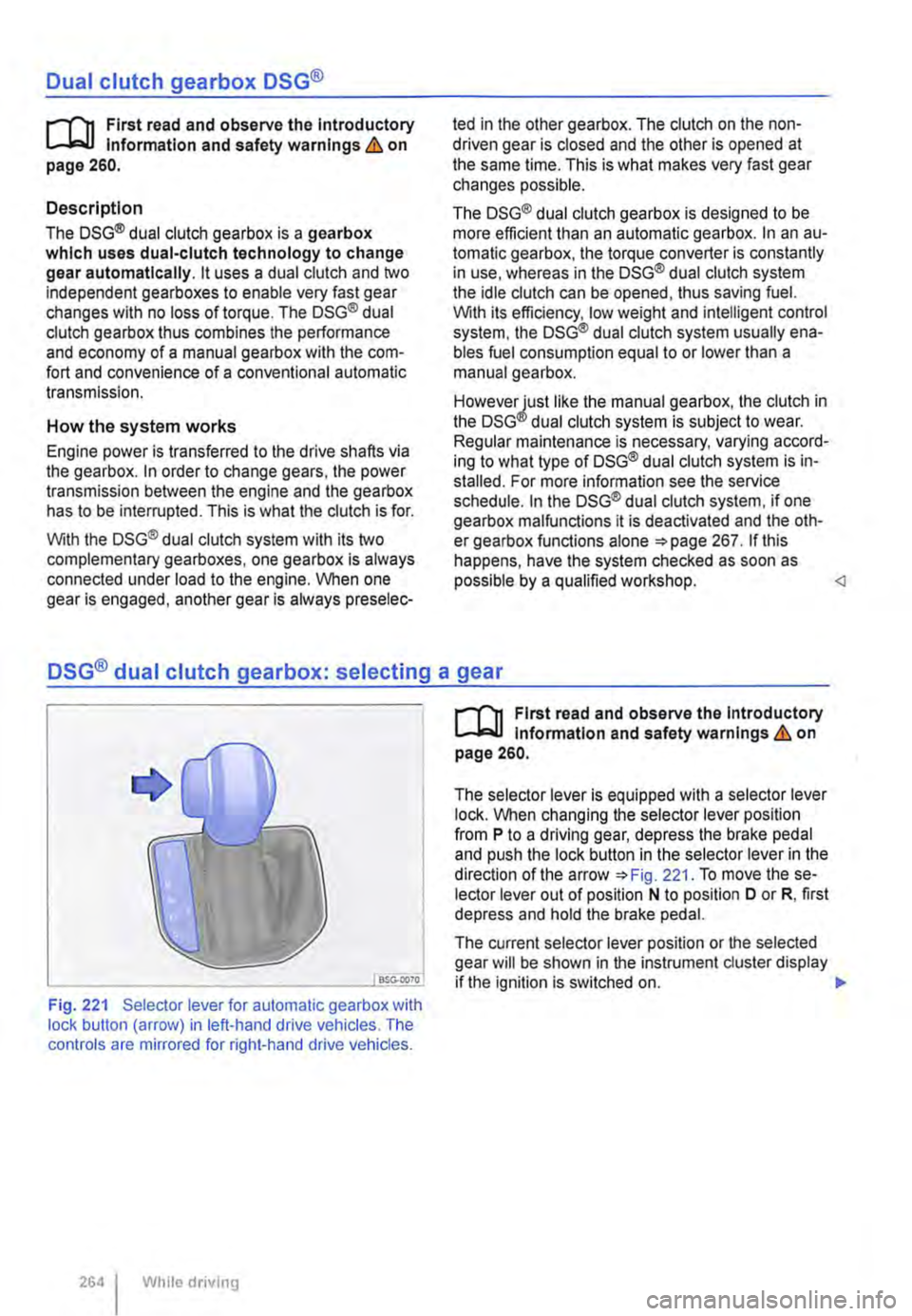
Fig. 221 Selector lever for automatic gearbox with lock button (arrow) in left-hand drive vehicles. The controls are mirrored for right-hand drive vehicles.
264 I While driving
r-('n First read and observe the Introductory L-.lo:on Information and safety warnings & on page 260.
The selector lever is equipped with a selector lever lock. When changing the selector lever position from P to a driving gear, depress the brake pedal and push the lock button in the selector lever in the direction of the arrow *Fig. 221. To move the se-lector lever out of position N to position D or R, first depress and hold the brake pedal.
The current selector lever position or the selected gear will be shown in the instrument duster display if the ignition is switched on. .,..