2021 TOYOTA PROACE EV towing
[x] Cancel search: towingPage 3 of 360

3
Contents
Stop & Start 166Under-inflation detection 168Driving and manoeuvring aids - General recommendations 170Head-up display 172Memorising speeds 173Speed Limit Recognition and Recommendation 174Speed limiter 176Cruise control - particular recommendations 178Cruise control 179Adaptive Cruise Control 181Active Safety Brake with Collision Risk Alert and Intelligent emergency braking assistance 185Lane departure warning system 187Distraction detection 188Blind Spot Monitoring System 190Parking sensors 191VisioPark Light 193Top Rear Vision 194
7Practical informationCompatibility of fuels 197Refuelling 197Misfuel prevention (Diesel) 199Charging system (Electric) 199Charging the traction battery (Electric) 207Energy economy mode 2 11Snow chains 2 11Towing device 212Roof bars / Roof rack 213Bonnet 214Engine compartment 215Checking levels 216
Speed checks 218AdBlue® (Diesel engines) 221Free-wheeling 223Advice on care and maintenance 225
8In the event of a breakdownWarning triangle 227Running out of fuel (Diesel) 227Tool box 228Temporary puncture repair kit 229Spare wheel 233Changing a bulb 237Changing a fuse 24312 V battery / Accessory battery 246Towing 250
9Technical dataEngine technical data and towed loads 252Diesel engines 253Electric motor 257Dimensions 259Identification markings 262
10Bluetooth® audio systemFirst steps 263Steering mounted controls 264Menus 265Radio 265DAB (Digital Audio Broadcasting) radio 267Media 268Telephone 271Frequently asked questions 274
11TOYOTA Pro TouchFirst steps 276
Steering mounted controls 277Menus 278Applications 279Radio 280DAB (Digital Audio Broadcasting) radio 282Media 282Telephone 284Settings 287Frequently asked questions 289
12 TOYOTA Pro Touch with navigation systemFirst steps 291Steering mounted controls 292Menus 293Voice commands 294Navigation 298Connected navigation 301Applications 303Radio 306DAB (Digital Audio Broadcasting) radio 308Media 308Telephone 310Settings 313Frequently asked questions 315
■ Alphabetical index
Page 50 of 360

50
The monitoring system is deactivated: the indicator lamp in the button goes off and the direction indicators flash for about 2 seconds.
NOTIC E
When the vehicle automatically locks itself again (as happens if a door or the boot is not opened within 30 seconds of unlocking), the monitoring system is also reactivated
automatically.
Triggering of the alarm
This is indicated by sounding of the siren and flashing of the direction indicators for 30 seconds.The monitoring functions remain active until the alarm has been triggered ten times in succession.When the vehicle is unlocked, rapid flashing of the indicator lamp in the button indicates that the alarm was triggered during your absence. When the ignition is switched on, this flashing stops immediately.
Locking the vehicle
with exterior perimeter
monitoring only
Deactivate the interior volumetric monitoring to avoid the unwanted triggering of the alarm, in certain cases such as:
– Slightly open window.– Washing the vehicle.– Changing a wheel.– Towing the vehicle.– Transport on a ship or ferry.
Deactivating interior volumetric
monitoring
► Switch off the ignition and within 10 seconds press the alarm button until the indicator lamp is on fixed.► Exit the vehicle.► Immediately lock the vehicle using the remote control or the "Smart Entry & Start" system.Only exterior perimeter monitoring is activated; the red indicator lamp in the button flashes every second.To take effect, this deactivation must be performed whenever the ignition is switched off.
Reactivating interior volumetric
monitoring
► Deactivate exterior perimeter monitoring by unlocking the vehicle using the remote control or the "Smart Entry & Start" system.The indicator lamp in the button goes off.► Reactivate the full alarm system by locking the vehicle using the remote control or the "Smart Entry & Start" system.The red indicator lamp in the button once again flashes every second.
Locking the vehicle without
activating the alarm
► Lock or deadlock the vehicle using the key (integral to the remote control) in the driver's door lock.
Failure of the remote control
To deactivate the monitoring functions:► unlock the vehicle using the key (integral to the remote control) in the driver's door lock,► open the door; the alarm is triggered,► switch on the ignition; the alarm stops; the indicator lamp in the button goes off.
Malfunction
When the ignition is switched on, the fixed lighting of the red indicator lamp in the button indicates a system malfunction.Have it checked by any authorized Toyota retailer or Toyota authorized repairer, or any reliable repairer.
Automatic activation
(Depending on the country of sale)The system is activated automatically 2 minutes after the last door or the boot is closed.► To avoid triggering the alarm on entering the vehicle, first press the unlocking button on the remote control or unlock the vehicle using the “Smart Entry & Start” system.
Page 74 of 360

74
Depending on the country of sale, the wells can be dismantled and removed through the rear so that bulky objects can be stowed underneath the bench seat.
NOTIC E
Do not attach anything to the cab fixing structure.Do not exceed the number of passengers indicated on the registration certificate.In the rear, the loading area is intended for
carrying goods only.You are advised to place the goods or heavy objects as far forwards as possible in the loading area (towards the cab) and secure them by means of straps using the stowing rings on the floor.The rear seat belt frames are not designed to secure the load being carried.
Folding Crew Cab
The Crew Cab has a folding bench seat, seat belts and side windows. It is separated from the loading area by the bench seat by a high-strength grille.
Folded position
► With just one hand, pull one of the straps A upwards to fold the bench seat.
► Using handle B, guide the movement of the bench seat until it locks in the folded position.
Bench seat position
► To put the bench seat back in place, pull the strap C to unlock the bench seat, then release the strap.► Then, using only the handle B, guide the descent of the backrest to tip the assembly until it locks in the bench seat position.
Page 75 of 360

75
Ease of use and comfort
1
WARNI NG
Never put your hand underneath the bench seat to guide it downwards, as you could get your fingers trapped.Ensure there are no objects or feet beneath the bench seat or obstructing the anchorage system, preventing the assembly from being correctly locked.
WARNI NG
Do not attach anything to the cab fixing structure.Do not exceed the number of passengers indicated on the registration certificate.In the rear, the load space is intended for carrying goods only.It is recommended to place goods or heavy objects as far forwards as possible in the load space (towards the cab) and secure them by means of straps using the stowing rings on the floor.The rear seat belt frames are not designed to secure the load being carried.
Interior fittings
Mats
Fitting
When fitting it on the driver's side, only use the mountings present on the carpet.The other mats are simply laid over the carpet.
Removing/refitting
► To remove it on the driver's side, move
the seat as far back as possible and give the fasteners a quarter turn.
► To refit it, position the mat and replace the fasteners, giving them a quarter turn.► Check that the mat is secured correctly.
WARNI NG
To avoid any risk of jamming the pedals:– Only use mats which are suited to the fixings already present in the vehicle; these fixings must be used.– Never fit one mat on top of another.The use of mats not approved by TOYOTA may interfere with access to the pedals and hinder the operation of the cruise control/speed limiter.The approved mats have two fasteners located underneath the seat.
In row 2 and row 3
Page 79 of 360

79
Ease of use and comfort
1
NOTIC E
If the power consumption becomes too high and when required by the vehicle's electrical system (particular weather conditions, electrical overload, etc.), the power supply to the socket will be cut off; the green indicator lamp goes off
Load space cover
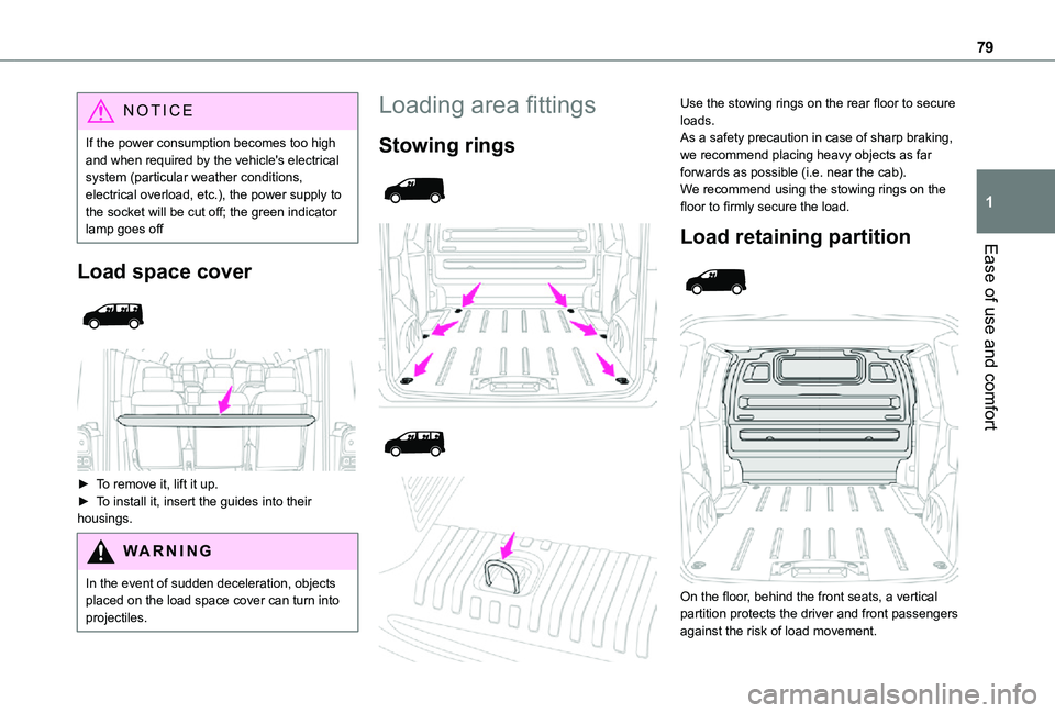
► To remove it, lift it up.
► To install it, insert the guides into their housings.
WARNI NG
In the event of sudden deceleration, objects placed on the load space cover can turn into projectiles.
Loading area fittings
Stowing rings
Use the stowing rings on the rear floor to secure loads.As a safety precaution in case of sharp braking, we recommend placing heavy objects as far forwards as possible (i.e. near the cab).We recommend using the stowing rings on the floor to firmly secure the load.
Load retaining partition
On the floor, behind the front seats, a vertical partition protects the driver and front passengers against the risk of load movement.
Page 80 of 360

80
Steel or glazed partitions separate the loading area from the cab.
Recommendations on
loading
WARNI NG
The weight of the load must comply with the Gross Train Weight (GTW).For more information on Engine technical data and towed loads, refer to the corresponding section.
WARNI NG
If you are using a carrying system (roof bars/roof rack), comply with the maximum loads associated with this system.For more information on Roof bars/Roof rack, refer to the corresponding section.
WARNI NG
Make sure that the size, shape and volume of the loads carried are compatible with the highway code and safety regulations and do not impair the driver’s field of vision.
WARNI NG
The load must be evenly distributed in the loading area so as not to interfere with driving the vehicle.Place the load close to the side panels, or even push it against the side panels between the wheel arches.However, it is recommended that heavy objects are placed as close to the cab as possible as a precaution in case of sharp braking.
WARNI NG
Firmly secure all parts of the load using the stowing rings on the floor of the loading area.For more information on the Interior fittings and in particular on the stowing rings, refer to the corresponding section.
WARNI NG
To avoid the risk of injury or accident, the load must be made stable so that it cannot slide, tip over, fall or be thrown. To do this, use only retaining straps that conform to current standards (DIN for example).For more information on putting straps in place, refer to the manufacturer’s user guide.There must not be any empty space between the components of the load.To prevent the load sliding, there must not be any empty space between the load and the panels of the vehicle.As well as the straps, optimise the stability of the load with stable handling equipment (wedges, rigid blocks of wood or padding).
WARNI NG
When washing your vehicle, never clean the inside directly using a water jet.
Page 81 of 360

81
Ease of use and comfort
1
Seating area fittings
High load retaining net
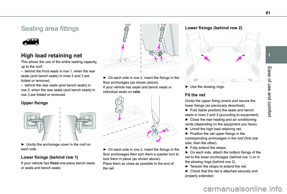
This allows the use of the entire loading capacity, up to the roof:– behind the front seats in row 1, when the rear seats (and bench seats) in rows 2 and 3 are folded or removed,– behind the rear seats (and bench seats) in row 2, when the rear seats (and bench seats) in row 3 are folded or removed.
Upper fixings
► Unclip the anchorage cover in the roof on each side.
Lower fixings (behind row 1)
If your vehicle has fixed one-piece bench seats or seats and bench seats:
► On each side in row 2, insert the fixings in the floor anchorages (as shown above).If your vehicle has seats and bench seats or individual seats on rails:
► On each side in row 2, insert the fixings in the floor anchorages then turn them a quarter turn to lock them in place (as shown above).Place them as close as possible to the end of the rail.
Lower fixings (behind row 2)
► Use the stowing rings.
Fit the net
Unclip the upper fixing covers and secure the lower fixings (as previously described).► Fold (table position) the seats and bench seats in rows 2 and 3 (according to equipment).► Close the rear heating and air conditioning vents (depending on the equipment you have).► Unroll the high load retaining net.
► Position the net upper fixings in the corresponding anchorages in the roof (first one side, then the other).► Fully extend the straps.► On each side, attach the bottom fixings of the net to the lower anchorages (behind row 1) or in the stowing rings (behind row 2).► Tension the straps to extend the net.► Check that the net is attached securely and properly extended.
Page 84 of 360

84
Unfolding
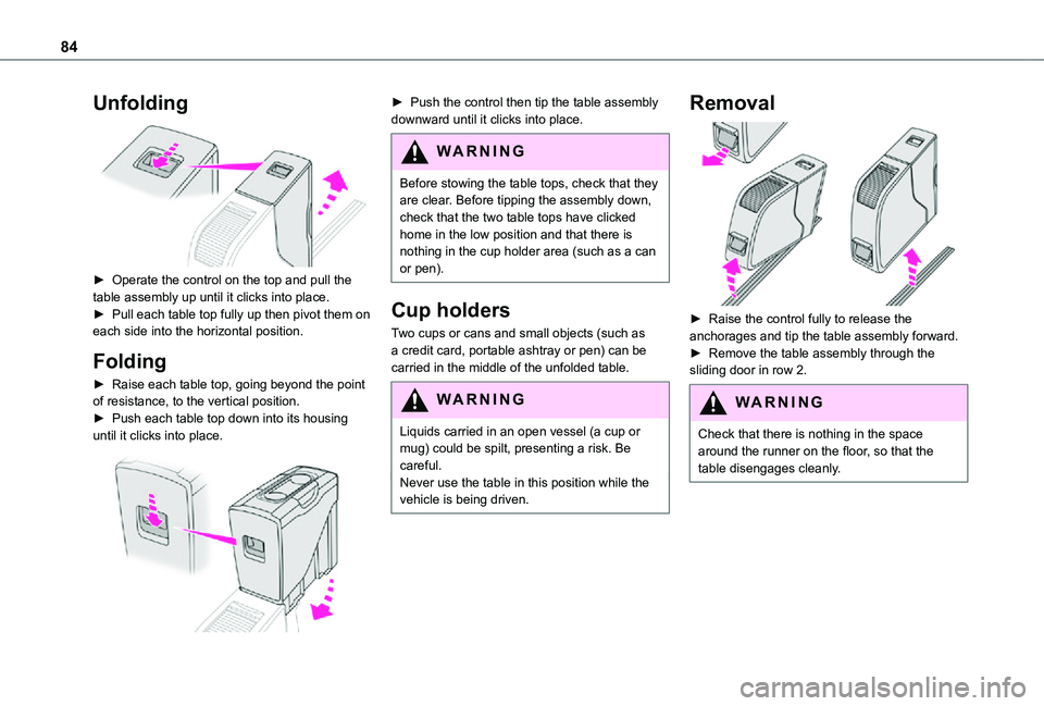
► Operate the control on the top and pull the table assembly up until it clicks into place.► Pull each table top fully up then pivot them on each side into the horizontal position.
Folding
► Raise each table top, going beyond the point of resistance, to the vertical position.► Push each table top down into its housing until it clicks into place.
► Push the control then tip the table assembly downward until it clicks into place.
WARNI NG
Before stowing the table tops, check that they are clear. Before tipping the assembly down, check that the two table tops have clicked home in the low position and that there is nothing in the cup holder area (such as a can
or pen).
Cup holders
Two cups or cans and small objects (such as a credit card, portable ashtray or pen) can be carried in the middle of the unfolded table.
WARNI NG
Liquids carried in an open vessel (a cup or mug) could be spilt, presenting a risk. Be careful.Never use the table in this position while the vehicle is being driven.
Removal
► Raise the control fully to release the anchorages and tip the table assembly forward. ► Remove the table assembly through the sliding door in row 2.
WARNI NG
Check that there is nothing in the space around the runner on the floor, so that the table disengages cleanly.