2021 TOYOTA PROACE CITY VERSO Socket
[x] Cancel search: SocketPage 5 of 272

5
Overview
Instruments and controls
1.Bonnet release
2.Dashboard fuses
3.Horn
4.Instrument panel
5.AlarmCourtesy lampWarning lamp display for seat belts and front passenger airbagPanoramic roof blind controlInterior rear view mirrorMonitoring mirrorEmergency call button
6.Monochrome screen with audio system
Touch screen with TOYOTA Connect Radio or TOYOTA Connect Nav
7.USB port
8.HeatingManual air conditioningDual-zone automatic air conditioningFront demisting - defrostingRear screen demisting – defrosting
9.Electric parking brake"START/STOP" button
10.Gearbox
11 .12 V socket
12.230 V accessory socket
13.Glove boxUSB port (inside the glove box)
14.Glove box
15.Front passenger airbag deactivation (on the side of the glove box, with the door open)
Steering mounted controls
1.External lighting / direction indicators control leverVoice recognition activation button
2.Wiper / screenwash / trip computer control lever
3.Controls to select the multimedia source (SRC), manage music (LIST) and manage phone calls ("telephone" symbol)
4.Speed Limiter / Programmable Cruise Control / Adaptive cruise control controls
5.Instrument panel display mode selection wheel
6.Voice controlVolume adjustment
7.Audio system setting controls
Page 49 of 272
49
Ease of use and comfort
3
The maximum permitted load is 6 kg (13 lb).
WARNI NG
In the event of sharp deceleration, objects placed in the central storage compartment of the roof may be transformed into projectiles.
Rear storage compartment
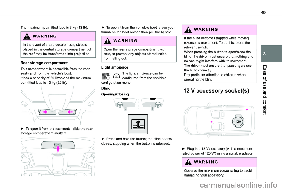
This compartment is accessible from the rear
seats and from the vehicle's boot.It has a capacity of 60 litres and the maximum permitted load is 10 kg (22 lb).
► To open it from the rear seats, slide the rear storage compartment shutters.
► To open it from the vehicle’s boot, place your thumb on the boot recess then pull the handle.
WARNI NG
Open the rear storage compartment with care, to prevent any objects stored inside from falling out.
Light ambience
The light ambience can be configured from the vehicle’s configuration menu.
Blind
Opening/Closing
► Press and hold the button; the blind opens/closes, stopping when the button is released.
WARNI NG
If the blind becomes trapped while moving, reverse its movement. To do this, press the relevant switch.When pressing the button to open/close the blind, the driver must ensure that nothing and no one might interfere with its movement.The driver must ensure that passengers use the blind correctly.Pay particular attention to children when operating the blind.
12 V accessory socket(s)
► Plug in a 12 V accessory (with a maximum rated power of 120 W) using a suitable adapter.
WARNI NG
Observe the maximum power rating to avoid damaging your accessory.
Page 50 of 272
50
WARNI NG
The connection of an electrical device not approved by TOYOTA, such as a USB charger, may adversely affect the operation of vehicle electrical systems, causing faults such as poor radio reception or interference with displays in the screens.
USB port(s)
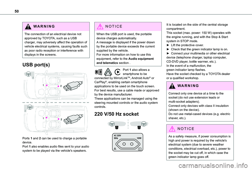
Ports 1 and 2 can be used to charge a portable device.
Port 1 also enables audio files sent to your audio system to be played via the vehicle's speakers.
NOTIC E
When the USB port is used, the portable device charges automatically.A message is displayed if the power drawn by the portable device exceeds the current supplied by the vehicle.For more information on how to use this equipment, refer to the Audio equipment and telematics section .
Port 1 also allows a smartphone to be connected by MirrorLinkTM, Android Auto® or CarPlay®, enabling certain smartphone applications to be used on the touch screen.For best results, use a cable made or approved by the device manufacturer.These applications can be managed using the steering mounted controls or the audio system controls.
220 V/50 Hz socket
AC 220 V
50Hz 120W
It is located on the side of the central storage compartment.This socket (max. power: 150 W) operates with the engine running, and with the Stop & Start system in STOP mode.► Lift the protective cover.► Check that the green indicator lamp is on.► Connect your multimedia or other electrical device (telephone charger, laptop computer, CD-DVD player, bottle warmer, etc.).In the event of a malfunction, the green indicator lamp flashes.Have the socket checked by a TOYOTA dealer or a qualified workshop.
WARNI NG
Connect only one device at a time to the socket (do not use extension leads or multi-socket adapters).Connect only devices with class II insulation (shown on the device).Do not use metal-cased devices (e.g. electric shaver, etc.).
NOTIC E
As a safety measure, if power consumption is high and power is required by the vehicle's
electrical system (due to severe weather conditions, electrical overload, etc.), power to the socket may be cut off, in which case the green indicator lamp goes off.
Page 75 of 272
75
Safety
5
General safety
recommendations
WARNI NG
Do not remove the labels attached in different places on your vehicle. They include safety warnings as well as identification information for the vehicle.
WARNI NG
For all work on your vehicle, use a qualified workshop that has the technical information, skills and equipment required, all of which a TOYOTA dealer is able to provide.
WARNI NG
Depending on country regulations, certain safety equipment may be mandatory: high
visibility safety vests, warning triangles, breathalysers, spare bulbs, spare fuses, fire extinguisher, first aid kit, mud flaps at the rear of the vehicle, etc.
WARNI NG
Installing electrical accessories:– The fitting of electrical equipment or accessories not approved by TOYOTA may cause excessive current consumption and faults and failures with the electrical system of your vehicle. Contact a TOYOTA dealer for information on the range of approved accessories.– As a safety measure, access to the diagnostic socket, used for the vehicle's electronic systems, is reserved strictly for TOYOTA dealers or qualified workshops, equipped with the special tools required (risk of malfunctions of the vehicle's electronic systems that could cause breakdowns or serious accidents). The Manufacturer cannot be held responsible if this advice is not followed.– Any modification or adaptation not intended or authorised by TOYOTA or carried out without meeting the technical requirements
defined by the Manufacturer will result in the suspension of the commercial warranty.
W ARNI NG
Installation of accessory radio communication transmittersBefore installing a radio communication transmitter with an external aerial, you must without fail contact a TOYOTA dealer for the specification of transmitters which can be fitted (frequency, maximum power, aerial position, specific installation requirements), in line with the Vehicle Electromagnetic Compatibility Directive (2004/104/EC).
Page 156 of 272
156
Towing device with quickly
detachable towball
No tools are required to install or remove this genuine towing device.
NOTIC E
Trailers with LED lamps are not compatible with the wiring harness of this device.
Fitting
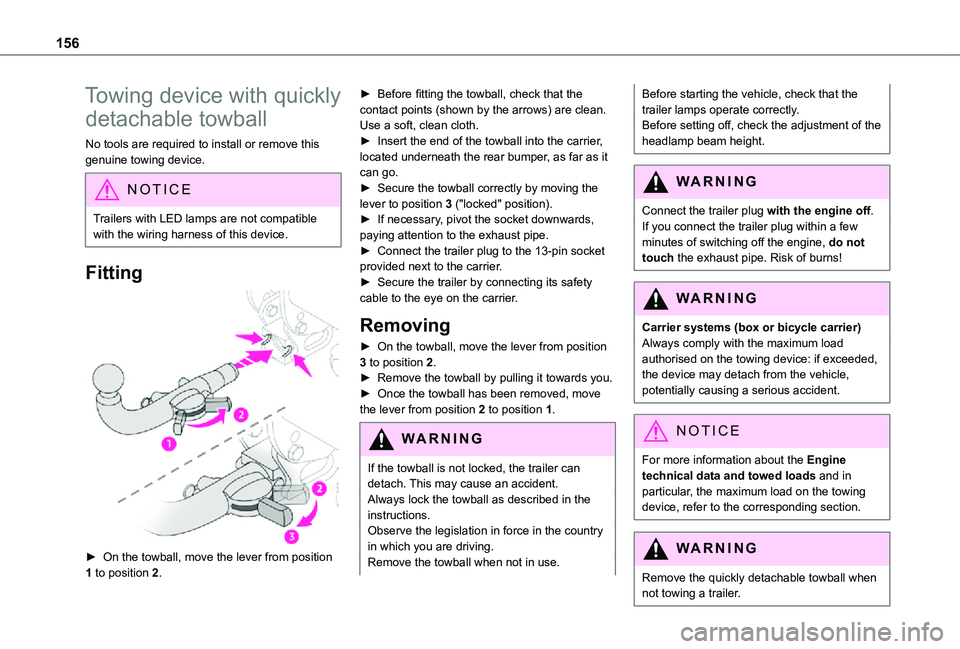
► On the towball, move the lever from position 1 to position 2.
► Before fitting the towball, check that the contact points (shown by the arrows) are clean. Use a soft, clean cloth.► Insert the end of the towball into the carrier, located underneath the rear bumper, as far as it can go.► Secure the towball correctly by moving the lever to position 3 ("locked" position).► If necessary, pivot the socket downwards, paying attention to the exhaust pipe.► Connect the trailer plug to the 13-pin socket provided next to the carrier.► Secure the trailer by connecting its safety cable to the eye on the carrier.
Removing
► On the towball, move the lever from position 3 to position 2.► Remove the towball by pulling it towards you.► Once the towball has been removed, move the lever from position 2 to position 1.
WARNI NG
If the towball is not locked, the trailer can detach. This may cause an accident.Always lock the towball as described in the instructions.Observe the legislation in force in the country in which you are driving.Remove the towball when not in use.
Before starting the vehicle, check that the trailer lamps operate correctly.Before setting off, check the adjustment of the headlamp beam height.
WARNI NG
Connect the trailer plug with the engine off.If you connect the trailer plug within a few minutes of switching off the engine, do not
touch the exhaust pipe. Risk of burns!
WARNI NG
Carrier systems (box or bicycle carrier)Always comply with the maximum load authorised on the towing device: if exceeded, the device may detach from the vehicle, potentially causing a serious accident.
NOTIC E
For more information about the Engine technical data and towed loads and in particular, the maximum load on the towing device, refer to the corresponding section.
WARNI NG
Remove the quickly detachable towball when not towing a trailer.
Page 170 of 272
170
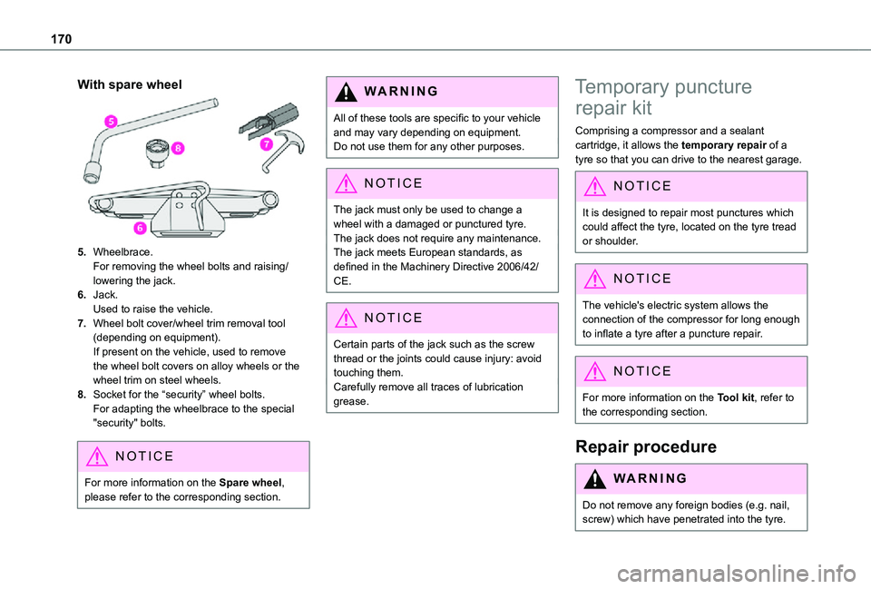
With spare wheel
5.Wheelbrace.For removing the wheel bolts and raising/lowering the jack.
6.Jack.Used to raise the vehicle.
7.Wheel bolt cover/wheel trim removal tool (depending on equipment).If present on the vehicle, used to remove the wheel bolt covers on alloy wheels or the wheel trim on steel wheels.
8.Socket for the “security” wheel bolts.For adapting the wheelbrace to the special "security" bolts.
NOTIC E
For more information on the Spare wheel, please refer to the corresponding section.
WARNI NG
All of these tools are specific to your vehicle and may vary depending on equipment.Do not use them for any other purposes.
NOTIC E
The jack must only be used to change a
wheel with a damaged or punctured tyre.The jack does not require any maintenance.The jack meets European standards, as defined in the Machinery Directive 2006/42/CE.
NOTIC E
Certain parts of the jack such as the screw thread or the joints could cause injury: avoid touching them.Carefully remove all traces of lubrication grease.
Temporary puncture
repair kit
Comprising a compressor and a sealant cartridge, it allows the temporary repair of a tyre so that you can drive to the nearest garage.
NOTIC E
It is designed to repair most punctures which
could affect the tyre, located on the tyre tread or shoulder.
NOTIC E
The vehicle's electric system allows the connection of the compressor for long enough to inflate a tyre after a puncture repair.
NOTIC E
For more information on the Tool kit, refer to the corresponding section.
Repair procedure
WARNI NG
Do not remove any foreign bodies (e.g. nail, screw) which have penetrated into the tyre.
Page 171 of 272
171
In the event of a breakdown
8
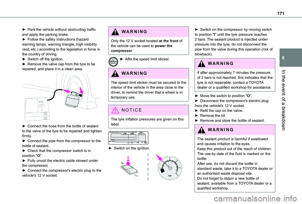
► Park the vehicle without obstructing traffic and apply the parking brake.► Follow the safety instructions (hazard warning lamps, warning triangle, high visibility vest, etc.) according to the legislation in force in the country of driving.► Switch off the ignition.► Remove the valve cap from the tyre to be repaired, and place it in a clean area.
► Connect the hose from the bottle of sealant to the valve of the tyre to be repaired and tighten firmly.► Connect the pipe from the compressor to the bottle of sealant.► Check that the compressor switch is in position "O".► Fully uncoil the electric cable stowed under the compressor.► Connect the compressor's electric plug to the vehicle's 12 V socket.
WARNI NG
Only the 12 V socket located at the front of the vehicle can be used to power the compressor.
► Affix the speed limit sticker.
WARNI NG
The speed limit sticker must be secured to the interior of the vehicle in the area close to the driver, to remind the driver that a wheel is in temporary use.
NOTIC E
The tyre inflation pressures are given on this label.
► Switch on the ignition.
► Switch on the compressor by moving switch to position "I" until the tyre pressure reaches 2 bars. The sealant product is injected under pressure into the tyre; do not disconnect the pipe from the valve during this operation (risk of blowback).
WARNI NG
If after approximately 7 minutes the pressure
of 2 bars is not reached, this indicates that the tyre is not repairable; contact a TOYOTA dealer or a qualified workshop for assistance.
► Move the switch to position "O".► Disconnect the compressor's electric plug from the vehicle's 12 V socket.► Refit the cap on the valve.► Remove the kit.► Remove and store the bottle of sealant.
WARNI NG
The sealant product is harmful if swallowed and causes irritation to the eyes.Keep this product out of the reach of children.The use-by date of the fluid is marked on the bottle.After use, do not discard the bottle in standard waste, take it to a TOYOTA dealer or
an authorised waste disposal site.Do not forget to obtain a new bottle of sealant, available from a TOYOTA dealer or a qualified workshop.
Page 172 of 272
172
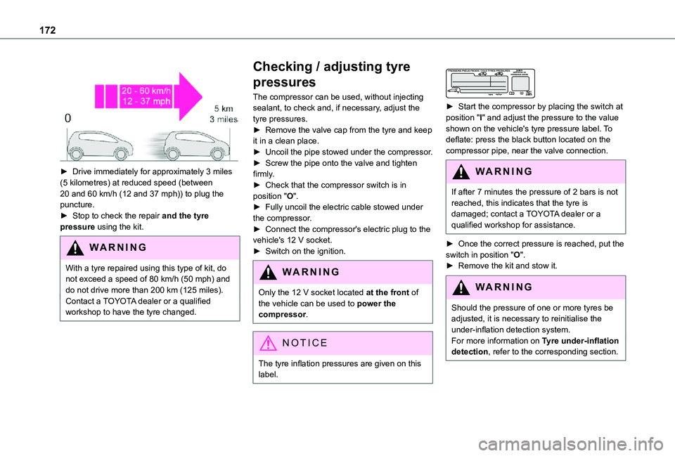
► Drive immediately for approximately 3 miles (5 kilometres) at reduced speed (between 20 and 60 km/h (12 and 37 mph)) to plug the puncture.► Stop to check the repair and the tyre pressure using the kit.
WARNI NG
With a tyre repaired using this type of kit, do not exceed a speed of 80 km/h (50 mph) and do not drive more than 200 km (125 miles).Contact a TOYOTA dealer or a qualified workshop to have the tyre changed.
Checking / adjusting tyre
pressures
The compressor can be used, without injecting sealant, to check and, if necessary, adjust the tyre pressures.► Remove the valve cap from the tyre and keep it in a clean place.► Uncoil the pipe stowed under the compressor.► Screw the pipe onto the valve and tighten firmly.► Check that the compressor switch is in position "O".► Fully uncoil the electric cable stowed under the compressor.► Connect the compressor's electric plug to the vehicle's 12 V socket.► Switch on the ignition.
WARNI NG
Only the 12 V socket located at the front of the vehicle can be used to power the compressor.
NOTIC E
The tyre inflation pressures are given on this label.
► Start the compressor by placing the switch at position "I" and adjust the pressure to the value shown on the vehicle's tyre pressure label. To deflate: press the black button located on the compressor pipe, near the valve connection.
WARNI NG
If after 7 minutes the pressure of 2 bars is not reached, this indicates that the tyre is damaged; contact a TOYOTA dealer or a qualified workshop for assistance.
► Once the correct pressure is reached, put the switch in position "O".► Remove the kit and stow it.
WARNI NG
Should the pressure of one or more tyres be adjusted, it is necessary to reinitialise the under-inflation detection system.For more information on Tyre under-inflation detection, refer to the corresponding section.