2021 TOYOTA PROACE CITY EV wheel
[x] Cancel search: wheelPage 206 of 320
206
Energy economy mode
This system manages the duration of use of certain functions, in order to conserve a sufficient level of charge in the battery with the ignition off.After switching off the engine and for a maximum cumulative period of around 30 minutes, you can continue to use functions such as the audio and telematic system, dipped beam headlamps or courtesy lamps.
Selecting the mode
A confirmation message is displayed when energy economy mode is entered, and the active functions are placed on standby.
NOTIC E
If a telephone call is in progress at the time, it will be maintained for around 10 minutes via the audio system’s hands-free system.
Exiting the mode
These functions are automatically reactivated the next time the vehicle is used.To restore the use of these functions immediately, start the engine and let it run:– For less than 10 minutes, to use the equipment for approximately 5 minutes.– For more than 10 minutes, to use the equipment for approximately 30 minutes.
Let the engine run for the specified duration to ensure that the battery charge is sufficient.To recharge the battery, avoid repeatedly or continuously restarting the engine.
WARNI NG
A flat battery prevents the engine from starting.For more information on the 12 V battery,
refer to the corresponding section.
Load reduction mode
This system manages the use of certain functions according to the level of charge remaining in the battery.When the vehicle is being driven, the load reduction function temporarily deactivates certain functions, such as the air conditioning and the heated rear screen.The deactivated functions are reactivated automatically as soon as conditions permit.
Snow chains
In wintry conditions, snow chains improve traction as well as the behaviour of the vehicle when braking.
WARNI NG
The snow chains must be fitted only to the front wheels. They must never be fitted to "space-saver" type spare wheels.
NOTIC E
Take account of the legislation specific to each country on the use of snow chains and the maximum authorised speed.
Use only the chains designed to be fitted to the type of wheel fitted to your vehicle:
Original tyre sizeMaximum link size (mm)
195/65 R159
205/60 R16
205/55 R17
215/65 R16
215/60 R17cannot be fitted with chains
You can also use snow socks.
Page 207 of 320
207
Practical information
7
For more information, contact a TOYOTA dealer or a qualified workshop.
Installation tips
► If you have to fit the chains during a journey, stop the vehicle on a flat surface on the side of the road.► Apply the parking brake and position any wheel chocks under the wheels to prevent movement of your vehicle.► Fit the chains following the instructions provided by the manufacturer.► Move off gently and drive for a few moments, without exceeding 50 km/h (31 mph).► Stop your vehicle and check that the snow chains are correctly tightened.
NOTIC E
It is strongly recommended that before you leave, you practise fitting the snow chains on a level and dry surface.
WARNI NG
Avoid driving with snow chains on roads that have been cleared of snow to avoid damaging your vehicle's tyres and the road surface. If your vehicle is fitted with alloy wheels, check
that no part of the chain or its fixings is in contact with the wheel rim.
Very cold climate screen
(Depending on version.)This removable device prevents the accumulation of snow around the radiator cooling fan.
NOTIC E
In case of difficulty with installation/removalContact any authorized Toyota retailer or Toyota authorized repairer, or any reliable repairer.
WARNI NG
Before any operation, ensure that the engine is off and the cooling fan has stopped.
WARNI NG
It is essential to remove them when:– the outside temperature exceeds 10°C.– recovery is in progress.– the speed is above 75 mph (120 km/h).
Fitting
► Hold the screen in front of the lower grille of the bumper.► First insert the upper and side fixing brackets into the bumper.► Tilt the screen downwards to engage the lower part of the screen into the bumper.► Check that the unit is firmly held by pressing around the edges.
Page 217 of 320
217
Practical information
7
Brake disc wear
For information on checking brake disc wear, contact a TOYOTA dealer or a qualified workshop.
Manual parking brake
If you notice excessive brake lever travel or decreased effectiveness, the parking brake must be adjusted, even between two services.This system must be checked by a TOYOTA dealer or a qualified workshop.
Electric parking brake
This system does not require any routine servicing. However, in the event of a problem, do not hesitate to have the system checked by a TOYOTA dealer or a qualified workshop.
NOTIC E
For more information on the Electric parking brake, refer to the corresponding section.
Wheels and tyres
The inflation pressure of all tyres, including the spare wheel, must be checked on "cold” tyres.The pressures indicated on the tyre pressure label are valid for "cold" tyres. If you have driven for more than 10 minutes or more than 10 km
(6 miles) at over 50 km/h (31 mph), add 0.3 bar (30 kPa) to the values indicated on the label.
WARNI NG
Under-inflation increases fuel consumption. Non-compliant tyre pressure causes premature wear on tyres and has an adverse effect on the vehicle's road holding - risk of an accident!
Driving with worn or damaged tyres reduces the braking and road holding performance of the vehicle. It is recommended to regularly check the condition of the tyres (tread and sidewalls) and wheel rims as well as the presence of the valves.When the wear indicators no longer appear set back from the tread, the depth of the grooves is less than 1.6 mm; it is imperative to replace the tyres.Using different size wheels and tyres from those specified can affect the lifetime of tyres, wheel rotation, ground clearance, the speedometer reading and have an adverse effect on road holding.Fitting different tyres on the front and rear axles can cause the VSC to mistime.Always mark the direction of rotation on the tyres that will be stored when fitting winter or summer tyres. Store them in a cool, dry place and away from direct exposure to the sun's rays.
Winter or 4-seasons tyres can be identified by this symbol on their sidewalls.
AdBlue® (Diesel engines)
To respect the environment and ensure compliance with the Euro 6 standard, without adversely affecting the performance or fuel consumption of its Diesel engines, TOYOTA has taken the decision to equip its vehicles with a system that associates SCR (Selective Catalytic Reduction) with a Diesel particle filter (DPF) for the treatment of exhaust gases.
SCR system
Using a liquid called AdBlue® that contains urea, a catalytic converter turns up to 85% of the nitrogen oxides (NOx) into nitrogen and water, which are harmless to health and the environment.The AdBlue® is contained in a special tank holding about 17 litres.
Its capacity allows a driving range of approximately 3,000 miles (5,000 km) (which may vary considerably depending on your driving style and the vehicle). An alert system is automatically triggered when the remaining range reaches 1,500 miles (2,400 km), i.e. once the reserve level has been reached.Several alerts are triggered successively during the remaining 1,500 miles (2,400 km) until the
tank is empty and the vehicle is immobilised.
Page 220 of 320
220
► With an AdBlue® pump: insert the nozzle and fill the tank until the nozzle automatically cuts out.
WARNI NG
In order not to overfill the AdBlue® tank:– Add between 10 and 13 litres using AdBlue® containers.– Stop after the nozzle’s first automatic cut-
out, if you are refilling at a service station.The system only registers AdBlue® top-ups of 5 litres or more.
WARNI NG
If the AdBlue® tank is completely empty – which is confirmed by the message "Top up AdBlue: Starting impossible" – it is essential to add at least 5 litres.
After refilling
► Refit the blue cap to the tank filler and turn it clockwise, as far as it will go.► Close the fuel filler flap.
Do not dispose of AdBlue® bottles or containers in the household waste.Place them in a container reserved for this purpose or take them back to where you purchased them.
Free-wheeling
In certain situations, you must allow the vehicle to free-wheel (while being towed, on a rolling road, in an automatic car wash, or being transported by rail or sea freight, etc.).The procedure varies according to the type of gearbox and parking brake.
WARNI NG
Do not leave the vehicle unattended while coasting.
With a manual gearbox and
electric parking brake /
To release them
► With the engine running and while depressing the brake pedal, move the gear selector to the neutral position.
► While depressing the brake pedal, switch off the ignition.► Release the brake pedal, then switch on the ignition again.► While depressing the brake pedal, press the control lever to release the parking brake.► Release the brake pedal, then switch off the ignition.
Reverting to normal operation
► While depressing the brake pedal, restart the engine.
With an automatic gearbox
and electric parking brake /
To release them
► With the engine running and while depressing the brake pedal, set the gear selector to N.► While depressing the brake pedal, switch off the ignition.
► Release the brake pedal, then switch on the ignition again.► While depressing the brake pedal, press the control lever to release the parking brake.► Release the brake pedal, then switch off the ignition.
Reverting to normal operation
► While depressing the brake pedal, restart the engine, then set the gear selector to P.
Page 221 of 320
221
Practical information
7
With drive selector and
electric parking brake /
Release procedure
► With the vehicle stationary and the engine running, depress the brake pedal and select mode N.Within 5 seconds:► Depress and hold the brake pedal, then observe this order: switch off the ignition (if start with START/STOP, press and hold the button for 2 seconds) and move the push selector forwards or backwards.► Release the brake pedal, then switch on the ignition again.► Place your foot on the brake and press the electric parking brake control to release it.► Release the brake pedal, then switch off the ignition.
NOTIC E
Keyless Entry and StartingYou must not depress the brake pedal while switching the ignition on again, then switching it off. If you do, the engine will start, requiring you to restart the procedure.
WARNI NG
A message is displayed on the instrument panel to confirm the unlocking of the wheels for 15 minutes.When the vehicle is free-wheeling, the audio system cannot be updated (message displayed on the instrument panel).
Reverting to normal operation
► While depressing the brake pedal, restart the engine, then set the gear selector to P.
Advice on care and
maintenance
General recommendations
Observe the following recommendations to avoid damaging the vehicle.
Exterior
WARNI NG
Never use a high-pressure jet wash in the engine compartment - risk of damaging the electrical components!Do not wash the vehicle in bright sunshine or extremely cold conditions.
NOTIC E
When washing the vehicle at an automatic roller-brush car wash, be sure to lock the doors and, depending on version, remove the electronic key.When using a pressure washer, hold the lance at least 30 cm from the vehicle (particularly when cleaning areas containing chipped paint, sensors or seals).Promptly clean up any stains containing chemicals liable to damage the vehicle's paint (including tree resin, bird droppings, insect secretions, pollen and tar).If justified by the environment, clean the vehicle frequently to remove salty deposits (in coastal areas), soot (in industrial areas) and mud/salts (in wet or cold areas). These substances can be highly corrosive.Contact any authorized Toyota retailer or Toyota authorized repairer, or any reliable repairer for advice on removing stubborn stains requiring special products (such as tar
or insect removers).Preferably, have paint touch-ups performed by any authorized Toyota retailer or Toyota authorized repairer, or any reliable repairer.
Page 223 of 320
223
In the event of a breakdown
8
Running out of fuel
(Diesel)
With Diesel engines, the fuel system must be primed if you run out of fuel.Before starting to prime the system, it is essential to put at least 5 litres of Diesel into the fuel tank.
NOTIC E
For more information on Refuelling and on Misfuel prevention (Diesel), refer to the corresponding section.
NOTIC E
For more information on the Engine compartment, in particular the location of these components under the bonnet, refer to the corresponding section.
With Euro 6.2/6.3 engines
► Switch on the ignition (without starting the engine).► Wait around 1 minute and switch off the ignition.► Operate the starter motor to start the engine.If the engine does not start at the first attempt,
do not keep trying, but restart the procedure.
Tool kit
► For easier access, move the seat(s) forward.
Accessing the tools
Vehicle with electric motor
With temporary puncture repair kitThe tools are located in the passenger footwell.With spare wheelThe tools are located under the right-hand front seat.To access the tools:– With non-adjustable front seat, lift the seat cushion by placing your hand between the cushion and the backrest.– With adjustable front seat, move the seat forward as far as possible.The jack is located in the passenger footwell.
Vehicle with Petrol or Diesel engine
With temporary puncture repair kitThe kit is located under the right-hand front seat.With spare wheel
The jack is located under the right-hand front seat.The tools are located under the left-hand front seat.
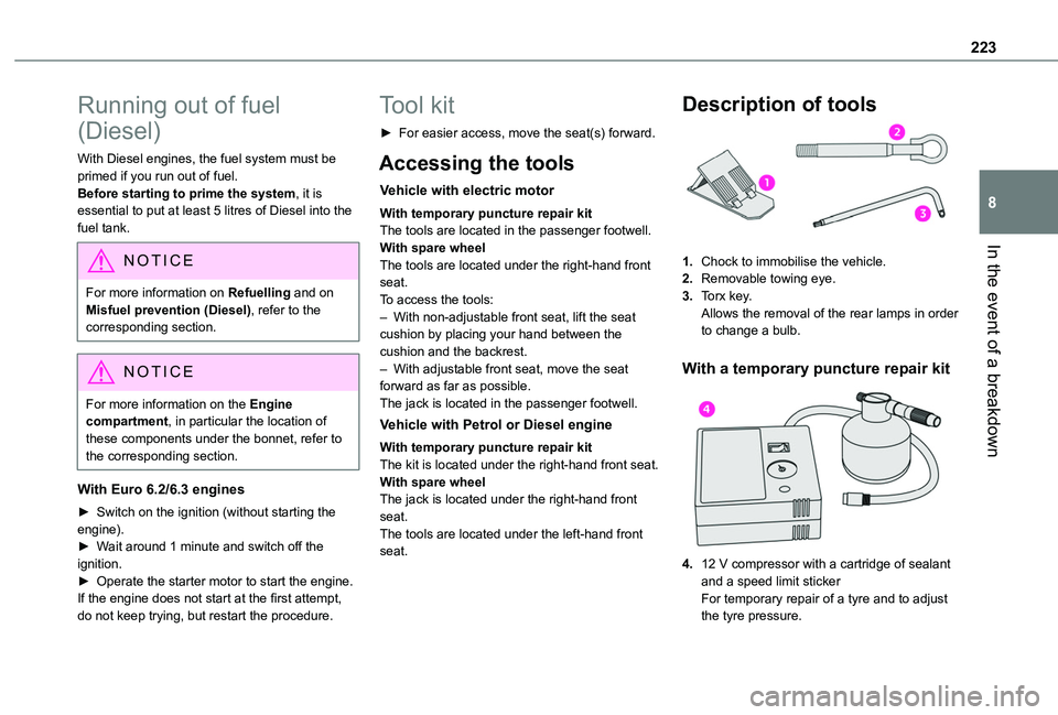
Description of tools
1.Chock to immobilise the vehicle.
2.Removable towing eye.
3.Torx key.Allows the removal of the rear lamps in order to change a bulb.
With a temporary puncture repair kit
4.12 V compressor with a cartridge of sealant and a speed limit stickerFor temporary repair of a tyre and to adjust
the tyre pressure.
Page 224 of 320
224
WARNI NG
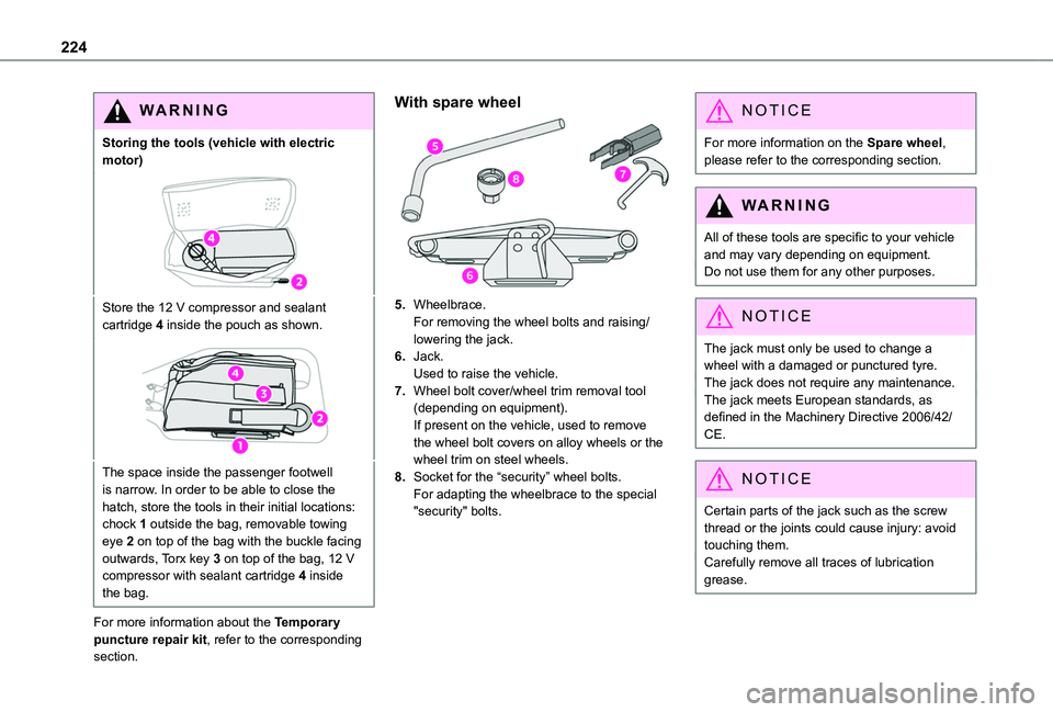
Storing the tools (vehicle with electric motor)
Store the 12 V compressor and sealant cartridge 4 inside the pouch as shown.
The space inside the passenger footwell is narrow. In order to be able to close the hatch, store the tools in their initial locations: chock 1 outside the bag, removable towing eye 2 on top of the bag with the buckle facing outwards, Torx key 3 on top of the bag, 12 V compressor with sealant cartridge 4 inside the bag.
For more information about the Temporary puncture repair kit, refer to the corresponding section.
With spare wheel
5.Wheelbrace.For removing the wheel bolts and raising/lowering the jack.
6.Jack.Used to raise the vehicle.
7.Wheel bolt cover/wheel trim removal tool (depending on equipment).If present on the vehicle, used to remove the wheel bolt covers on alloy wheels or the wheel trim on steel wheels.
8.Socket for the “security” wheel bolts.For adapting the wheelbrace to the special "security" bolts.
NOTIC E
For more information on the Spare wheel, please refer to the corresponding section.
WARNI NG
All of these tools are specific to your vehicle and may vary depending on equipment.Do not use them for any other purposes.
NOTIC E
The jack must only be used to change a wheel with a damaged or punctured tyre.The jack does not require any maintenance.The jack meets European standards, as defined in the Machinery Directive 2006/42/CE.
NOTIC E
Certain parts of the jack such as the screw thread or the joints could cause injury: avoid touching them.Carefully remove all traces of lubrication grease.
Page 225 of 320
225
In the event of a breakdown
8
Temporary puncture
repair kit
Made up of a compressor and a sealant cartridge, it allows you to carry out a temporary repair of the tyre so that you can drive to the nearest garage.It is designed to repair most punctures located on the tyre tread.
NOTIC E
The vehicle's electric system allows the connection of the compressor to the 12 V power supply for long enough to repair a tyre after a puncture.
WARNI NG
Only the 12 V socket located at the front of the vehicle can be used to power the compressor.
NOTIC E
For more information on the Tool kit, refer to the corresponding section.
Repair procedure
WARNI NG
Do not remove any foreign bodies (e.g. nail, screw) which have penetrated into the tyre.
► Park the vehicle without obstructing traffic and apply the parking brake.► Follow the safety instructions (hazard
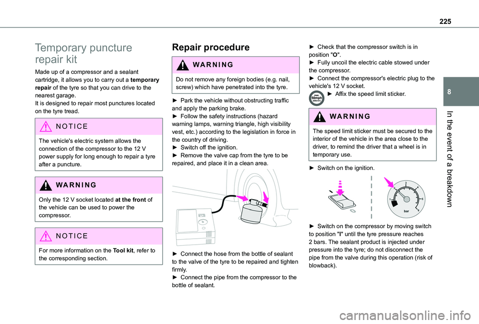
warning lamps, warning triangle, high visibility vest, etc.) according to the legislation in force in the country of driving.► Switch off the ignition.► Remove the valve cap from the tyre to be repaired, and place it in a clean area.
► Connect the hose from the bottle of sealant to the valve of the tyre to be repaired and tighten firmly.► Connect the pipe from the compressor to the bottle of sealant.
► Check that the compressor switch is in position "O".► Fully uncoil the electric cable stowed under the compressor.► Connect the compressor's electric plug to the vehicle's 12 V socket.► Affix the speed limit sticker.
WARNI NG
The speed limit sticker must be secured to the interior of the vehicle in the area close to the driver, to remind the driver that a wheel is in temporary use.
► Switch on the ignition.
► Switch on the compressor by moving switch to position "I" until the tyre pressure reaches 2 bars. The sealant product is injected under pressure into the tyre; do not disconnect the pipe from the valve during this operation (risk of blowback).