2021 RAM PROMASTER CITY radio
[x] Cancel search: radioPage 144 of 280
142MULTIMEDIA
STEERING WHEEL AUDIO CONTROLS — IF
EQUIPPED
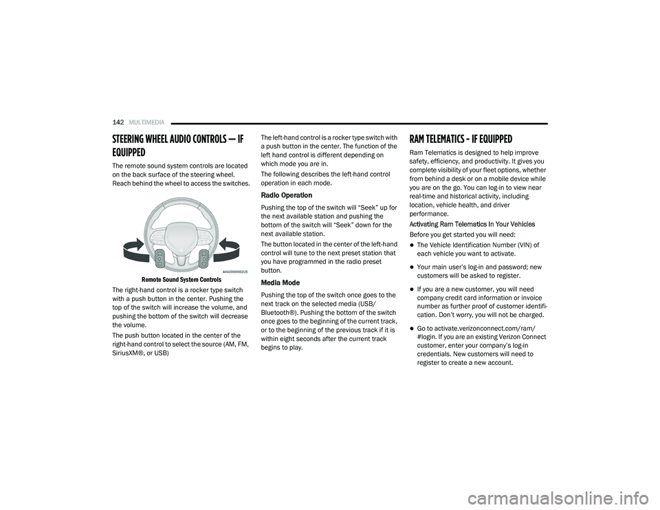
The remote sound system controls are located
on the back surface of the steering wheel.
Reach behind the wheel to access the switches.
Remote Sound System Controls
The right-hand control is a rocker type switch
with a push button in the center. Pushing the
top of the switch will increase the volume, and
pushing the bottom of the switch will decrease
the volume.
The push button located in the center of the
right-hand control to select the source (AM, FM,
SiriusXM®, or USB) The left-hand control is a rocker type switch with
a push button in the center. The function of the
left hand control is different depending on
which mode you are in.
The following describes the left-hand control
operation in each mode.
Radio Operation
Pushing the top of the switch will “Seek” up for
the next available station and pushing the
bottom of the switch will “Seek” down for the
next available station.
The button located in the center of the left-hand
control will tune to the next preset station that
you have programmed in the radio preset
button.
Media Mode
Pushing the top of the switch once goes to the
next track on the selected media (USB/
Bluetooth®). Pushing the bottom of the switch
once goes to the beginning of the current track,
or to the beginning of the previous track if it is
within eight seconds after the current track
begins to play.
RAM TELEMATICS - IF EQUIPPED
Ram Telematics is designed to help improve
safety, efficiency, and productivity. It gives you
complete visibility of your fleet options, whether
from behind a desk or on a mobile device while
you are on the go. You can log-in to view near
real-time and historical activity, including
location, vehicle health, and driver
performance.
Activating Ram Telematics In Your Vehicles
Before you get started you will need:
The Vehicle Identification Number (VIN) of
each vehicle you want to activate.
Your main user’s log-in and password; new
customers will be asked to register.
If you are a new customer, you will need
company credit card information or invoice
number as further proof of customer identifi
-
cation. Don’t worry, you will not be charged.
Go to activate.verizonconnect.com/ram/
#login. If you are an existing Verizon Connect
customer, enter your company’s log-in
credentials. New customers will need to
register to create a new account.
21_VM_OM_EN_USC_t.book Page 142
Page 145 of 280

MULTIMEDIA143
Manually enter the VIN(s) or upload a CSV file
with your VINs. A vehicle name is optional
and can be added later. Follow online instruc -
tions to complete your vehicle entry.
Create a password and enter billing informa -
tion. An email will be sent to you to complete
the final step. After that, you will be ready to
log-in and access Verizon Connect Fleet!
You are good to go! You will receive an email
confirming your vehicles are now online.
For more information, or to learn more, visit
www.verizonconnect.com/ram/.
Ram Telematics General Information
Modification Statement
Magneti Marelli has not approved any changes
or modifications to this device by the user. Any
changes or modifications could void the user’s
authority to operate the equipment.
Magneti Marelli n'approuve aucune
modification apportée à l'appareil par
l'utilisateur, quelle qu'en soit la nature. Tout
changement ou modification peuvent annuler
le droit d'utilisation de l'appareil par l'utilisateur. Interference Statement
This device complies with Part 15, 22, 24, and
27 of the FCC and Industry Canada
licence-exempt RSS standard(s). Operation is
subject to the following two conditions: (1) This
device may not cause interference, and (2) This
device must accept any interference, including
interference that may cause undesired
operation of the device.
Le présent appareil est conforme aux CNR
d'Industrie Canada applicables aux appareils
radio exempts de licence. L'exploitation est
autorisée aux deux conditions suivantes: (1)
l'appareil ne doit pas produire de brouillage, et
(2) l'utilisateur de l'appareil doit accepter tout
brouillage radioélectrique subi, même si le
broulliage est susceptible d'en compromettre le
fonctionnement.
RF Exposure
This equipment complies with FCC and IC
radiation exposure limits set forth for an
uncontrolled environment. The antenna should
be installed and operated with minimum
distance of 20 cm between the radiator and
your body.Cet appareil est conforme aux limites
d'exposition aux rayonnements de la IC pour
environnement non contrôlé. L'antenne doit
être installé de façon à garder une distance
minmale de 20 centimètres entre la source de
rayonnements et votre corps.
RADIO OPERATION AND MOBILE PHONES
Under certain conditions, the mobile phone
being on in your vehicle can cause erratic or
noisy performance from your radio. This
condition may be lessened or eliminated by
relocating the mobile phone. This condition is
not harmful to the radio. If your radio
performance does not satisfactorily “clear” by
the repositioning of the phone, it is
recommended that the radio volume be turned
down or off during mobile phone operation
when not using Uconnect (if equipped).
5
21_VM_OM_EN_USC_t.book Page 143
Page 146 of 280
144MULTIMEDIA
Regulatory And Safety Information
USA/CANADA
Exposure to Radio Frequency Radiation
The radiated output power of the internal
wireless radio is far below the FCC and IC radio
frequency exposure limits. Nevertheless, the
wireless radio will be used in such a manner
that the radio is 8 in (20 cm) or further from the
human body.
The internal wireless radio operates within
guidelines found in radio frequency safety
standards and recommendations, which reflect
the consensus of the scientific community. The radio manufacturer believes the internal
wireless radio is safe for use by consumers. The
level of energy emitted is far less than the
electromagnetic energy emitted by wireless
devices such as mobile phones. However, the
use of wireless radios may be restricted in some
situations or environments, such as aboard
airplanes. If you are unsure of restrictions, you
are encouraged to ask for authorization before
turning on the wireless radio Ú
page 265.
21_VM_OM_EN_USC_t.book Page 144
Page 147 of 280
145
(Continued)
SAFETY
SAFETY FEATURES
Four-Wheel Anti-Lock Brake System (ABS)
ABS is designed to aid the driver in maintaining
vehicle control under adverse braking
conditions. The system operates with a
separate computer to modulate hydraulic
pressure, to prevent wheel lock-up and to help
avoid skidding on slippery surfaces.
The system's pump motor runs during an ABS
stop to provide regulated hydraulic pressure.
The pump motor makes a low humming noise
during operation, which is normal.
The ABS includes an amber ABS Warning Light.
When the light is illuminated, the ABS is not
functioning. The system reverts to standard
non-anti-lock brakes. Turning the ignition OFF
and ON again may reset the ABS if the fault
detected was only momentary.When you are in a severe braking condition
involving the use of the ABS, you will experience
some pedal drop as the vehicle comes to a stop.
This is the result of the system reverting to the
base brake system.
Engagement of the ABS may be accompanied
by a pulsing sensation. You may also hear a
clicking noise. These occurrences are normal
and indicate that the system is functioning
properly.
WARNING!
The ABS contains sophisticated electronic
equipment that may be susceptible to inter
-
ference caused by improperly installed or
high output radio transmitting equipment.
This interference can cause possible loss of
anti-lock braking capability. Installation of
such equipment should be performed by
qualified professionals.
Pumping of the Anti-Lock Brakes will
diminish their effectiveness and may lead
to a collision. Pumping makes the stopping
distance longer. Just press firmly on your
brake pedal when you need to slow down or
stop.
The ABS cannot prevent the natural laws of
physics from acting on the vehicle, nor can
it increase braking or steering efficiency
beyond that afforded by the condition of the
vehicle brakes and tires or the traction
afforded.
The ABS cannot prevent collisions,
including those resulting from excessive
speed in turns, following another vehicle
too closely, or hydroplaning.
The capabilities of an ABS equipped vehicle
must never be exploited in a reckless or
dangerous manner that could jeopardize
the user’s safety or the safety of others.
WARNING! (Continued)
6
21_VM_OM_EN_USC_t.book Page 145
Page 154 of 280

152SAFETY
Check TPMS Warnings
The Tire Pressure Monitoring Warning Light will
flash on and off for 75 seconds and remain on
solid when a system fault is detected, an
audible chime will be activated and a proper
text message will be displayed. If the ignition
key is cycled, this sequence will repeat
providing the system fault still exists. The Tire
Pressure Monitoring Warning Light will turn off
when the fault condition no longer exists. A
system fault can occur with any of the following
scenarios:
1. Jamming due to electronic devices or
driving next to facilities emitting the same
radio frequencies as the TPM sensors.
2. Installing some form of aftermarket window tinting that affects radio wave signals.
3. Snow or ice around the wheels or wheel housings. 4. Using tire chains on the vehicle.
5. Using wheels/tires not equipped with TPM
sensors.
NOTE:
Your vehicle can be equipped with either a Tire
Service Kit, a compact spare tire or a regular
size spare tire (with or without original TPMS
sensor).
1. Tire Service Kit (original tire sealant – if equipped): After fixing the punctured tire
with original tire sealant, the original
situation will be restored, so system will
turn off the telltale during the normal drive.
2. Compact Spare Tire – if equipped: The compact spare wheel is not equipped with a
TPMS sensor. So when mounted, during the
normal drive the system will turn on the
telltale (flashing for approximately
75 seconds then remains solid). This
condition persists until a wheel equipped
with original TPMS sensor has been
mounted on the vehicle. 3. Regular size spare tire (not equipped with
TPMS sensor): When mounted, during the
normal drive the system will turn on the
telltale (flashing for approximately
75 seconds then remains solid). This
condition persists until a wheel equipped
with original TPMS sensor has been
mounted on the vehicle. Then the system
will be restored and the telltale will turn off
during the normal drive.
4. Regular size spare tire (equipped with TPMS sensor): When mounted, the telltale will
turn off during the normal drive.
5. In all the above cases, please check the replacement tire inflation pressure before
driving your vehicle.
6. In case of tire replacement, if the vehicle is driven for short periods of time, then the
system can take a while to be restored.
NOTE:
For a correct Tire Pressure Monitoring behavior,
please wait for about 20 minutes in key-off
during each tire substitution.
21_VM_OM_EN_USC_t.book Page 152
Page 166 of 280
164SAFETY
The steering wheel hub trim cover and the
upper passenger side of the instrument panel
separate and fold out of the way as the air bags
inflate to their full size. The front air bags fully
inflate in less time than it takes to blink your
eyes. The front air bags then quickly deflate
while helping to restrain the driver and front
passenger.
Knee Impact Bolsters
The Knee Impact Bolsters help protect the
knees of the driver and front passenger, and
position the front occupants for improved
interaction with the front air bags.
Supplemental Driver Knee Air Bag
This vehicle is equipped with a Supplemental
Driver Knee Air Bag mounted in the instrument
panel below the steering column. The
Supplemental Driver Knee Air Bag provides enhanced protection during a frontal impact by
working together with the seat belts,
pretensioners, and front air bags.
Supplemental Side Air Bags
Supplemental Seat-Mounted Side Air Bags
(SABs)
This vehicle is equipped with Supplemental
Seat-Mounted Side Air Bags (SABs).
Supplemental Seat-Mounted Side Air Bags
(SABs) are located in the outboard side of the
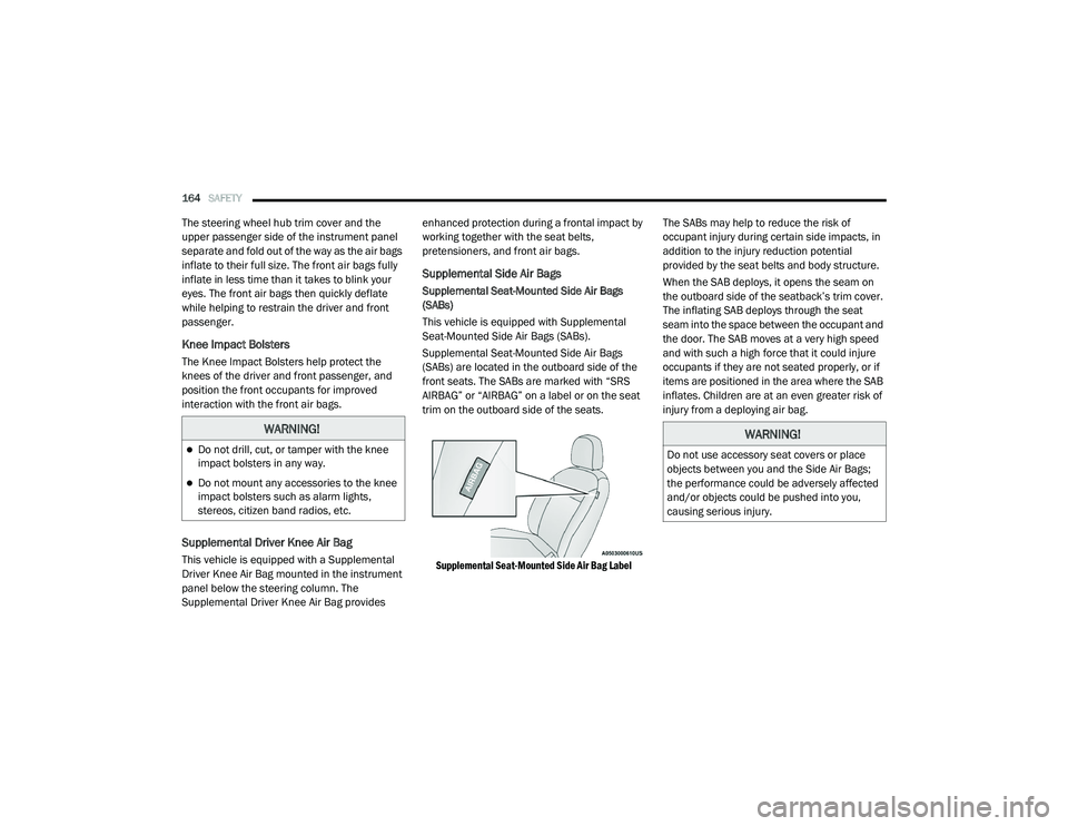
front seats. The SABs are marked with “SRS
AIRBAG” or “AIRBAG” on a label or on the seat
trim on the outboard side of the seats.
Supplemental Seat-Mounted Side Air Bag Label
The SABs may help to reduce the risk of
occupant injury during certain side impacts, in
addition to the injury reduction potential
provided by the seat belts and body structure.
When the SAB deploys, it opens the seam on
the outboard side of the seatback’s trim cover.
The inflating SAB deploys through the seat
seam into the space between the occupant and
the door. The SAB moves at a very high speed
and with such a high force that it could injure
occupants if they are not seated properly, or if
items are positioned in the area where the SAB
inflates. Children are at an even greater risk of
injury from a deploying air bag.
WARNING!
Do not drill, cut, or tamper with the knee
impact bolsters in any way.
Do not mount any accessories to the knee
impact bolsters such as alarm lights,
stereos, citizen band radios, etc.
WARNING!
Do not use accessory seat covers or place
objects between you and the Side Air Bags;
the performance could be adversely affected
and/or objects could be pushed into you,
causing serious injury.
21_VM_OM_EN_USC_t.book Page 164
Page 194 of 280

192IN CASE OF EMERGENCY
Interior Fuses
The interior fuse panel is part of the Body
Control Module (BCM) and is located on the
driver's side under the instrument panel.
Fuse Panel CoverFuse Panel Cavity Locations
CavityMini Fuse Description
F535 Amp Beige KL 30 (+30) - IPC, FTM
F38 20 Amp Yellow Central Doors Locking
F36 15 Amp Blue KL 30 (+30) - TPMS, EOBD, HVAC, Radio, USB, SGW
F43 15 Amp Blue Bi-Directional Washer Pump
F48 20 Amp Yellow Passenger Power Windows
F50 7.5 Amp Brown KL 15 (+15) - Air-Bag
F51 7.5 Amp Brown KL 15 (+15) - External Mirror Adjustment Command, HVAC, RVC, HWB Coils
F37 5 Amp Beige KL 15 (+15) - Brake Pedal Switch (N.O.), IPC, Brake Pedal Switch (N.C.)
F49 5 Amp Beige KL 15 (+15) - PAM, CSS Lighting, TTM, SGW, and Heaters Light, ECM Backlighting
F31 5 Amp Beige KL 15a (INT A) - HWB, MCO
F47 20 Amp Yellow Driver Power Windows
21_VM_OM_EN_USC_t.book Page 192
Page 208 of 280
206IN CASE OF EMERGENCY
See below steps to prepare for jump starting:
1. Apply the parking brake, shift the
automatic transmission into PARK (P) and
turn the ignition to STOP.
2. Turn off the heater, radio, and all electrical accessories.
3. If using another vehicle to jump-start the battery, park the vehicle within the jumper
cables reach, apply the parking brake and
make sure the ignition is OFF.
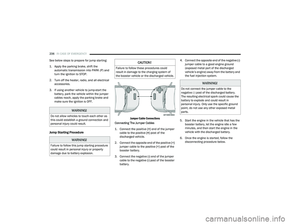
Jump Starting Procedure
Jumper Cable Connections
Connecting The Jumper Cables
1. Connect the positive
(+) end of the jumper
cable to the positive (+)
post of the
discharged vehicle.
2. Connect the opposite end of the positive (+)
jumper cable to the positive (+) post of the
booster battery.
3. Connect the negative (-) end of the jumper
cable to the negative (-) post of the booster
battery. 4. Connect the opposite end of the negative
(-)
jumper cable to a good engine ground
(exposed metal part of the discharged
vehicle’s engine) away from the battery and
the fuel injection system.
5. Start the engine in the vehicle that has the booster battery, let the engine idle a few
minutes, and then start the engine in the
vehicle with the discharged battery.
6. Once the engine is started, follow the disconnecting procedure below.
WARNING!
Do not allow vehicles to touch each other as
this could establish a ground connection and
personal injury could result.
WARNING!
Failure to follow this jump starting procedure
could result in personal injury or property
damage due to battery explosion.
CAUTION!
Failure to follow these procedures could
result in damage to the charging system of
the booster vehicle or the discharged vehicle.
WARNING!
Do not connect the jumper cable to the
negative (-) post of the discharged battery.
The resulting electrical spark could cause the
battery to explode and could result in
personal injury. Only use the specific ground
point, do not use any other exposed metal
parts.
21_VM_OM_EN_USC_t.book Page 206