2021 PEUGEOT PARTNER lock
[x] Cancel search: lockPage 156 of 260
154
In the event of a breakdown
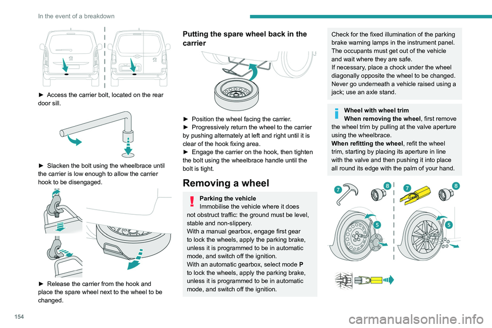
► Access the carrier bolt, located on the rear
door sill.
► Slacken the bolt using the wheelbrace until
the carrier is low enough to allow the carrier
hook to be disengaged.
► Release the carrier from the hook and
place the spare wheel next to the wheel to be
changed.
Putting the spare wheel back in the
carrier
► Position the wheel facing the carrier .
► Progressively return the wheel to the carrier
by pushing alternately at left and right until it is
clear of the hook fixing area.
►
Engage the carrier on the hook, then tighten
the bolt using the wheelbrace handle until the
bolt is tight.
Removing a wheel
Parking the vehicle
Immobilise the vehicle where it does
not obstruct traffic: the ground must be level,
stable and non-slippery.
With a manual gearbox, engage first gear
to lock the wheels, apply the parking brake,
unless it is programmed to be in automatic
mode, and switch off the ignition.
With an automatic gearbox, select mode
P
to lock the wheels, apply the parking brake,
unless it is programmed to be in automatic
mode, and switch off the ignition.
Check for the fixed illumination of the parking
brake warning lamps in the instrument panel.
The occupants must get out of the vehicle
and wait where they are safe.
If necessary, place a chock under the wheel
diagonally opposite the wheel to be changed.
Never go underneath a vehicle raised using a
jack; use an axle stand.
Wheel with wheel trim
When removing the wheel , first remove
the wheel trim by pulling at the valve aperture
using the wheelbrace.
When refitting the wheel , refit the wheel
trim, starting by placing its aperture in line
with the valve and then pushing it into place
all round its edge with the palm of your hand.
Page 159 of 260
157
In the event of a breakdown
8The headlamps have polycarbonate lenses with a protective coating:
►
do not clean them with a dry or
abrasive cloth, nor with detergent or
solvent products,
►
use a sponge and soapy water or a pH
neutral product,
►
when using a high-pressure washer on
persistent marks, do not keep the lance
directed towards the lamps or their edges for
too long, so as not to damage their protective
coating and seals.
Changing a bulb must only be done with
the ignition off and after the lamp has
been switched off for several minutes - risk of
serious burns!
Do not touch the bulb directly with your
fingers, use a lint-free cloth.
It is essential only to use anti-ultraviolet
(UV) type bulbs, so as not to damage the
headlamp.
Always replace a failed bulb with a new bulb
of the same type and specification.
Opening the bonnet / Accessing the
bulbs
With the engine warm, proceed with caution -
risk of burns!
Take care with objects or clothing that could
be caught in the blades of the cooling fan -
risk of strangulation!
Halogen bulbs (Hx)
To ensure good quality lighting, check
that the bulb is correctly positioned in its
housing.
After changing a bulb
To refit, carry out the fitting operations in
reverse order.
Close the protective cover very carefully to
guarantee the sealing of the lamps.
Types of bulb
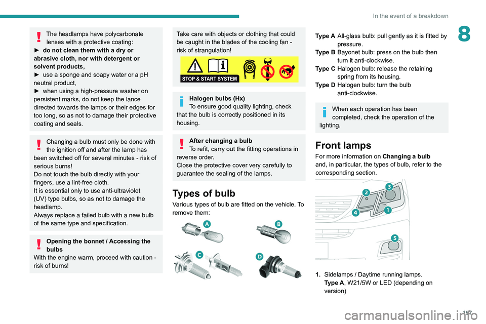
Various types of bulb are fitted on the vehicle. To
remove them:
Type A All-glass bulb: pull gently as it is fitted by
pressure.
Type B Bayonet bulb: press on the bulb then
turn it anti-clockwise.
Type C Halogen bulb: release the retaining
spring from its housing.
Type D Halogen bulb: turn the bulb
anti-clockwise.
When each operation has been
completed, check the operation of the
lighting.
Front lamps
For more information on Changing a bulb
and, in particular, the types of bulb, refer to the
corresponding section.
1. Sidelamps / Daytime running lamps.
Type
A, W21/5W or LED (depending on
version)
Page 160 of 260
158
In the event of a breakdown
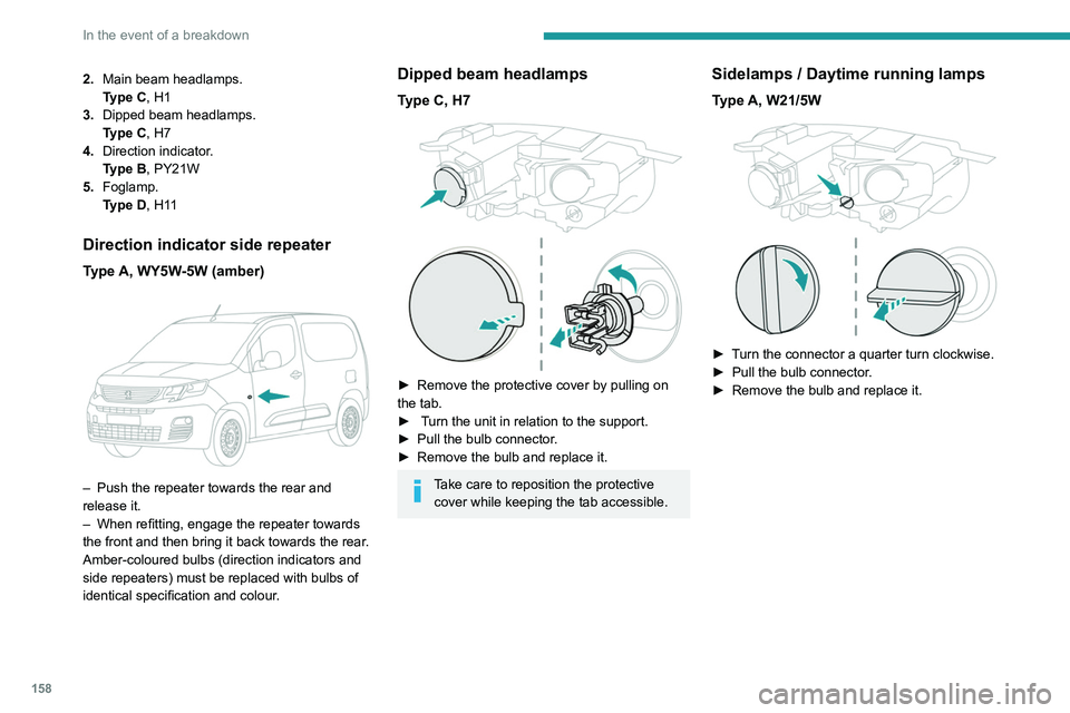
2.Main beam headlamps.
Type
C, H1
3. Dipped beam headlamps.
Type
C, H7
4. Direction indicator.
Type
B, PY21W
5. Foglamp.
Type
D, H11
Direction indicator side repeater
Type A, WY5W-5W (amber)
– Push the repeater towards the rear and
release it.
–
When refitting, engage the repeater towards
the front and then bring it back towards the rear
.
Amber-coloured bulbs (direction indicators and
side repeaters) must be replaced with bulbs of
identical specification and colour.
Dipped beam headlamps
Type C, H7
► Remove the protective cover by pulling on
the tab.
►
Turn the unit in relation to the support.
►
Pull the bulb connector
.
►
Remove the bulb and replace it.
Take care to reposition the protective cover while keeping the tab accessible.
Sidelamps / Daytime running lamps
Type A, W21/5W
► Turn the connector a quarter turn clockwise.
► Pull the bulb connector .
►
Remove the bulb and replace it.
Main beam headlamps
Type C, H1
► Remove the protective cover by pulling on
the tab.
► Unclip the unit in relation to the support.
► Pull the bulb connector.
► Remove the bulb and replace it.
Take care to reposition the protective
cover while keeping the tab accessible.
Direction indicators
Type B, PY21W
Rapid flashing of a direction indicator
lamp (left or right) indicates that one of
Page 161 of 260
159
In the event of a breakdown
8Main beam headlamps
Type C, H1
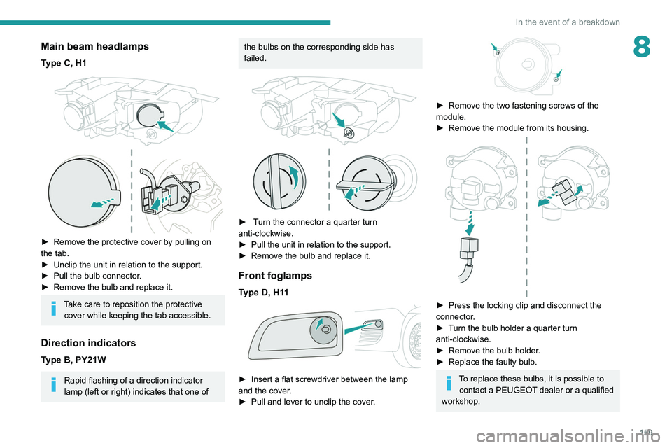
► Remove the protective cover by pulling on
the tab.
►
Unclip the unit in relation to the support.
►
Pull the bulb connector
.
►
Remove the bulb and replace it.
Take care to reposition the protective cover while keeping the tab accessible.
Direction indicators
Type B, PY21W
Rapid flashing of a direction indicator
lamp (left or right) indicates that one of
the bulbs on the corresponding side has
failed.
► Turn the connector a quarter turn
anti-clockwise.
►
Pull the unit in relation to the support.
►
Remove the bulb and replace it.
Front foglamps
Type D, H11
► Insert a flat screwdriver between the lamp
and the cover .
►
Pull and lever to unclip the cover
.
► Remove the two fastening screws of the
module.
►
Remove the module from its housing.
► Press the locking clip and disconnect the
connector .
►
T
urn the bulb holder a quarter turn
anti-clockwise.
►
Remove the bulb holder
.
►
Replace the faulty bulb.
To replace these bulbs, it is possible to contact a PEUGEOT dealer or a qualified
workshop.
Page 162 of 260

160
In the event of a breakdown
Rear lamps
For more information on Changing a bulb
and, in particular, the types of bulb, refer to the
corresponding section.
With side-hinged doors/tailgate
1. Brake lamps/sidelamps.
Type
B, P21/5W
2. Direction indicators.
Type
B, PY21W (amber)
3. Reversing lamps.
Type
B, P21W
4. Foglamps.
Type
B, P21W
► From the inside, disconnect the electrical
connector at the rear of the lamps.
► Remove the two fixing bolts using the Torx
key provided in your vehicle.
For more information on the Tool kit, please
refer to the corresponding section.
►
From the outside, pull the whole lamp unit
towards you (with side-hinged doors ) or
towards the centre of the vehicle (with tailgate
).
► Open the tabs, then pull out the lamp holder .
► Remove the faulty bulb by pressing lightly on
it while turning it a quarter turn anti-clockwise.
►
Replace the bulb.
Take care to reposition the tabs and the wiring correctly to avoid trapping the
wire.
After changing a rear direction indicator bulb, the reinitialisation time is
approximately 2 minutes or more.
Number plate lamps
Type A, W5W - 5W
With side-hinged doors
► Unclip the interior trim.
► Disconnect the connector by moving aside
its tab.
► Turn the bulb holder a quarter turn
anti-clockwise.
► Change the bulb.
► Put the bulb holder back in place and
reconnect the connector.
► Put the trim back in place.
With tailgate
► Remove the plastic lens using a screwdriver.
► Change the bulb.
► Refit the plastic lens and press on it.
Third brake lamp
Type A, W16W - 16W
– Unscrew the two nuts.
Page 163 of 260

161
In the event of a breakdown
8► Unclip the interior trim.
► Disconnect the connector by moving aside
its tab.
►
T
urn the bulb holder a quarter turn
anti-clockwise.
►
Change the bulb.
►
Put the bulb holder back in place and
reconnect the connector
.
►
Put the trim back in place.
With tailgate
► Remove the plastic lens using a screwdriver .
► Change the bulb.
►
Refit the plastic lens and press on it.
Third brake lamp
Type A, W16W - 16W
– Unscrew the two nuts. –
Push the rods.
–
If necessary
, disconnect the connector to
remove the lamp.
–
Replace the bulb.
Changing a fuse
Accessing the tools
The extraction tweezers are located behind the
fusebox cover.
►
Unclip the cover by pulling at the top left, then
right.
►
Remove the cover completely
.
►
T
ake the tweezers from their housing.
Changing a fuse
Before changing a fuse:
► Identify the cause of the fault and fix it.
►
Stop all power consumption.
►
Immobilise the vehicle and switch the ignition
off.
►
Identify the defective fuse using the current
allocation tables and diagrams.
T
o replace a fuse, it is essential to:
►
Use the special tweezers to extract the fuse
from its housing and check the condition of its
filament.
►
Always replace the failed fuse with a fuse of
the same rating (same colour); use of a different
rating may cause malfunctions - risk of fire!
If the fault recurs after replacing a fuse, have
the electrical system checked by a PEUGEOT
dealer or a qualified workshop.
The fuse allocation tables and the corresponding diagrams are available
from a PEUGEOT dealer or from a qualified
workshop.
The replacement of a fuse not shown in the allocation tables may cause a serious
Page 164 of 260

162
In the event of a breakdown
malfunction of your vehicle. Contact a
PEUGEOT dealer or a qualified workshop.
Good
Failed
Tweezers
Installing electrical accessories
Your vehicle's electrical system is
designed to operate with standard or optional
equipment.
Before installing other electrical equipment
or accessories on your vehicle, contact a
PEUGEOT dealer or a qualified workshop.
PEUGEOT will not accept responsibility
for the cost incurred in repairing your
vehicle or for rectifying malfunctions resulting
from the installation of accessories not
supplied and not recommended by
PEUGEOT and not installed in accordance
with its instructions, in particular when the
combined consumption of all of the additional
equipment connected exceeds 10
milliamperes.
For more information on installing a
towbar or TAXI type equipment, contact a
PEUGEOT dealer.
Dashboard fuses
The fusebox is placed in the lower dashboard
(left-hand side).
Access to the fuses
► Unclip the cover by pulling at the top left, then
right.
The fuses described below vary according to the equipment in your vehicle.
Fuse No. Rating (A) Functions
F1 10Wireless
smartphone
charger, interior
electrochrome
rear view mirror.
Fuse No. Rating (A) Functions
F415Horn.
F6 20Screenwash
pump.
F7 1012
V socket
(rear).
F10 30 Electric locks
module.
F13 10 Telematics and
radio controls.
F14 5 Alarm, overload
indicator,
advanced
telematic unit.
F19 3 Trailer interface
unit.
F22 3 Surround Rear
Vision display
screen.
F23 5 Generic trailer
interface unit.
F27 5 Additional
heating.
F29 20 Audio system,
touch screen.
F32 15 12
V socket
(front).Fuse No. Rating (A) Functions
F34 5 Mirror control.
F36 5 USB socket.
Engine compartment fuses
The fusebox is placed in the engine
compartment near the battery.
Access to the fuses
► Release the two latches A.
► Remove the cover.
► Change the fuse.
► When you have finished, close the cover
carefully then engage the two latches A, to
ensure correct sealing of the fusebox.
Page 168 of 260
166
In the event of a breakdown
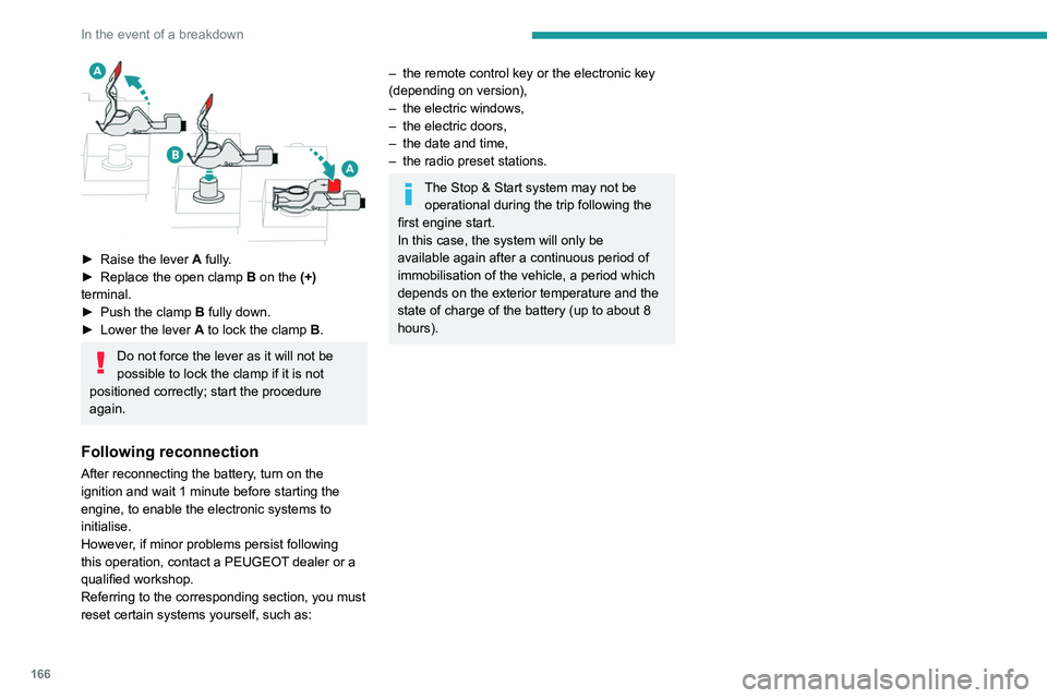
► Raise the lever A fully.
► Replace the open clamp B
on the (+)
terminal.
►
Push the clamp
B fully down.
►
Lower the lever A
to lock the clamp B.
Do not force the lever as it will not be
possible to lock the clamp if it is not
positioned correctly; start the procedure
again.
Following reconnection
After reconnecting the battery, turn on the
ignition and wait 1 minute before starting the
engine, to enable the electronic systems to
initialise.
However, if minor problems persist following
this operation, contact a PEUGEOT dealer or a
qualified workshop.
Referring to the corresponding section, you must
reset certain systems yourself, such as:
– the remote control key or the electronic key
(depending on version),
–
the electric windows,
–
the electric doors,
–
the date and time,
–
the radio preset stations.
The Stop & Start system may not be operational during the trip following the
first engine start.
In this case, the system will only be
available again after a continuous period of
immobilisation of the vehicle, a period which
depends on the exterior temperature and the
state of charge of the battery (up to about 8
hours).
Towing
Procedure for having your vehicle towed or for towing another vehicle us\
ing the towing eye.
General recommendations
Observe the legislation in force in the country where you are driving.
Ensure that the weight of the towing vehicle is higher than that of the \
towed vehicle.
The driver must remain at the wheel of the towed vehicle and must have a\
valid driving licence.
When towing a vehicle with all four wheels on the ground, always use an \
approved towbar; ropes and straps are prohibited.
The towing vehicle must move off gently.
When the vehicle is towed with its engine off, there is no longer braking and steering assistance.
A professional recovery service must be called if:
– broken down on a motorway or main road;
– not possible to put the gearbox into neutral, unlock the steering, or re\
lease the parking brake;
– not possible to tow a vehicle with an automatic gearbox, with the engine\
running;
– towing with only two wheels on the ground;
– four-wheel drive vehicle;
– no approved towbar available.
Towing constraints
Type of vehicle
(engine / gearbox)gearbox Font wheels on the
groundRear wheels on the
groundFlatbed
4 wheels on the ground
with towbar
Internal combustion /
Manual
Internal combustion /
Automatic
In case of battery or electric parking brake failure, it is essential to call a p
rofessional using flatbed recovery vehicles (excluding manual gearbox).