2021 Peugeot Landtrek tow bar
[x] Cancel search: tow barPage 5 of 176

3
Contents
7Practical information
Recommended fuel 88
Refuelling 88
Towing device 89
Snow chains 89
Roof bars 90
Bonnet 90
Engine compartment 91
Checking levels 92
Checks
94
Maintenance 96
Free-wheeling 102
Advice on care and maintenance 102
8In the event of a breakdown
Warning triangle 104
Fire extinguisher 104
Running out of fuel (Diesel) 105
Tool kit 105
Spare wheel 106
Changing a bulb 11 0
Changing a fuse 11 3
12
V battery 11 6
Towing the vehicle 11 9
9Technical data
Engine technical data and towed loads 122
Petrol engines 123
Diesel engines 124
Dimensions 125
Identification markings 125
10Bluetooth® radio
Menus 127
Steering mounted controls 128
Radio 128
Media 129
Telephone 129
11Peugeot Connect 10" Touchscreen
First steps 131
Steering mounted controls
131
Menus 132
Navigation 133
Radio 133
Music player 133
Telephone 134
Applications 135
Settings 136
■
Alphabetical index
Page 28 of 176
26
Ease of use and comfort
The backrest of the seat located next to the
driver, once in the table position, can also be
used as an armrest and has 2 cup/can holders
and a support strap.
For more information on the Seat belts,
refer to the corresponding section.
Folding the backrests
The backrests must only be operated with the vehicle stationary.
While driving, having a passenger in the rear,
behind the front benchseat is prohibited if the
benchseat backrests are tilted.
When sharp deceleration occurs, objects
placed on the folded backrest can turn into
projectiles.
Preliminary operations:
► Lower the head restraints.
► Check that no person or object will interfere
with folding down the backrests (clothing,
luggage, etc.).
► Check that the outer seat belt is properly
tensioned along the pillars, the central belt is
stowed and the tongues of the belts are correctly
in the stowed position.
Deactivation of the front passenger
airbag is recommended.
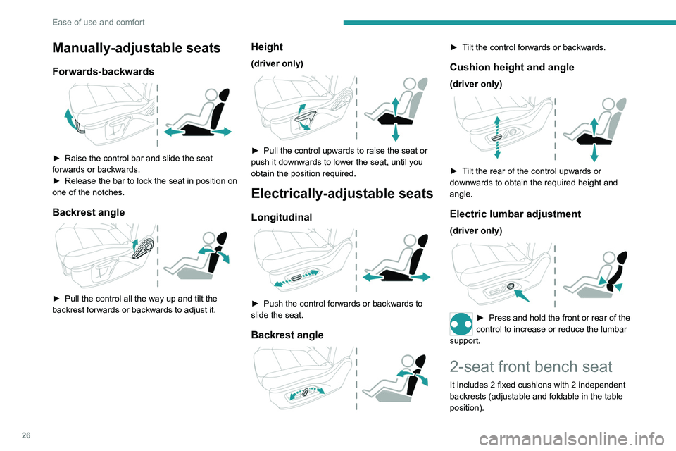
Manually-adjustable seats
Forwards-backwards
► Raise the control bar and slide the seat
forwards or backwards.
►
Release the bar to lock the seat in position on
one of the notches.
Backrest angle
► Pull the control all the way up and tilt the
backrest forwards or backwards to adjust it.
Height
(driver only)
► Pull the control upwards to raise the seat or
push it downwards to lower the seat, until you
obtain the position required.
Electrically-adjustable seats
Longitudinal
► Push the control forwards or backwards to
slide the seat.
Backrest angle
► Tilt the control forwards or backwards.
Cushion height and angle
(driver only)
► Tilt the rear of the control upwards or
downwards to obtain the required height and
angle.
Electric lumbar adjustment
(driver only)
► Press and hold the front or rear of the
control to increase or reduce the lumbar
support.
2-seat front bench seat
It includes 2 fixed cushions with 2 independent
backrests (adjustable and foldable in the table
position).
Page 41 of 176
39
Ease of use and comfort
3Storage boxes
Storage boxes are provided in the floor, under
the cushions of the rear bench seat.
They may contain the vehicle’s tools.
►
T
o open them, raise the corresponding
seat cushion and lift the carpet (depending on
version).
For more information on the Rear bench seat,
and especially on tilting the seat cushions, refer
to the corresponding section.
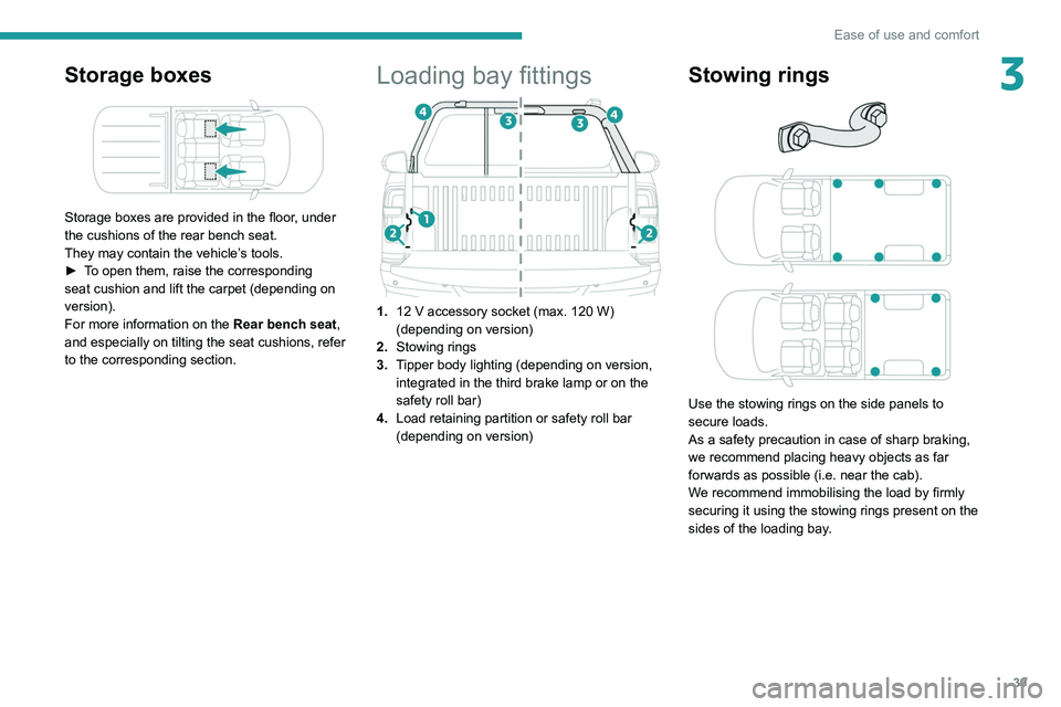
Loading bay fittings
1. 12 V accessory socket (max. 120 W)
(depending on version)
2. Stowing rings
3. Tipper body lighting (depending on version,
integrated in the third brake lamp or on the
safety roll bar)
4. Load retaining partition or safety roll bar
(depending on version)
Stowing rings
Use the stowing rings on the side panels to
secure loads.
As a safety precaution in case of sharp braking,
we recommend placing heavy objects as far
forwards as possible (i.e. near the cab).
We recommend immobilising the load by firmly
securing it using the stowing rings present on the
sides of the loading bay.
Page 42 of 176

40
Ease of use and comfort
Load retaining partition
On the structure of the loading bay, behind the
rear window, a vertical separation protects the
driver and passengers against the risk of load
movement.
Bars separate the loading area from the cab.
Retractable hooks, integrated into the upper bar,
are used to secure the loads in the loading bay.
Recommendations on
loading
The weight of the load must comply with the Gross Train Weight (GTW).
For more information on Engine technical
data and towed loads , refer to the
corresponding section.
Make sure that the size, shape and
volume of the loads carried are
compatible with the highway code and safety
regulations and do not impair the driver’s field
of vision.
The load must be evenly distributed in the loading area so as not to interfere
with driving the vehicle.
Place the load close to the side wall panels,
or push it against the side wall panels
between the wheel arches.
However, it is recommended that heavy
objects are placed as close to the cab as
possible as a precaution in case of sharp
braking.
Secure all loads firmly using the stowing
rings present on the side panels of the
loading bay.
For more information on the Loading bay
fittings, and in particular on the stowing
rings, refer to the corresponding section.
To avoid the risk of injury or accident, the load must be made stable so that it
cannot slide, tip over, fall or be projected. To
do this, use only retaining straps that conform
to current standards (DIN, for example).
For more information on putting straps in
place, refer to the manufacturer’s user guide.
To prevent the load from sliding, there must
not be any empty spaces between the load
items and the vehicle wall panels.
As well as the straps, optimise the stability
of the load with stable handling equipment
(wedges, rigid blocks of wood or padding).
When washing the vehicle, never clean
the interior directly with a water jet.
Loading bay lighting
Depending on version, the loading bay lighting is
integrated into the third brake lamp or positioned
at each end of the safety roll bar.
The tipper body
lighting only operates when the
vehicle is stationary.
Page 83 of 176
81
Driving
6This supplements the audible signal by
displaying bars on the screen that move
progressively nearer to the vehicle.
Front parking sensors
Supplementing the rear parking sensors, the
front parking sensors are triggered when an
obstacle is detected in front and the speed of the
vehicle is still below 6 mph (10 km/h).
Front parking sensor operation is suspended if
an obstacle is no longer detected or the vehicle
speed exceeds 6
mph (10 km/h).
The sound emitted by the speaker (front or rear) locates the obstacle relative to
the vehicle, in front or behind it.
Deactivation / Activation
► To deactivate or activate the system, press
this button.
The indicator lamp is lit when the system is
deactivated.
The state of the system stays in the memory
when the ignition is switched off.
The rear parking sensors system will be deactivated automatically if a trailer or
bicycle carrier is connected to a towing device
installed in accordance with the
manufacturer's recommendations.
Operating limits
If the boot is heavily loaded, the vehicle may tilt,
affecting distance measurements.
Malfunction
In the event of a malfunction when
changing into reverse, this warning lamp
comes on on the instrument panel, accompanied
by an onscreen message and an audible signal
(short beep).
Contact a PEUGEOT dealer or a qualified
workshop to have the system checked.
Reversing camera
Refer to the General recommendations on the
use of driving and manoeuvring aids .
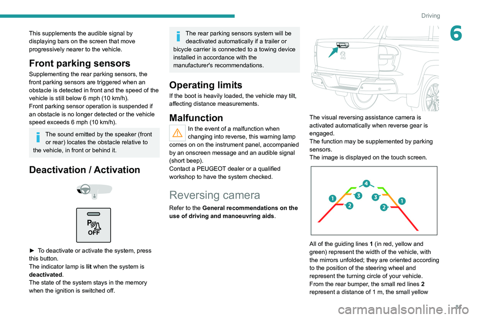
The visual reversing assistance camera is
activated automatically when reverse gear is
engaged.
The function may be supplemented by parking
sensors.
The image is displayed on the touch screen.
All of the guiding lines 1 (in red, yellow and
green) represent the width of the vehicle, with
the mirrors unfolded; they are oriented according
to the position of the steering wheel and
represent the turning circle of your vehicle.
From the rear bumper, the small red lines 2
represent a distance of 1 m, the small yellow
Page 92 of 176
90
Practical information
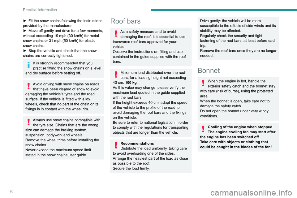
Opening
► Open the left-hand front door.
► Pull the interior release lever, located at the
bottom of the dashboard, towards you.
► Tilt the exterior safety catch to the left and
raise the bonnet.
► Unclip the stay from its housing and place it
in the support slot to hold the bonnet open.
* Depending on engine.
► Fit the snow chains following the instructions
provided by the manufacturer .
►
Move off gently and drive for a few moments,
without exceeding 19
mph (30 km/h) for metal
snow chains or 31 mph (50 km/h) for plastic
snow chains.
►
Stop the vehicle and check that the snow
chains are correctly tightened.
It is strongly recommended that you
practise fitting the snow chains on a level
and dry surface before setting off.
Avoid driving with snow chains on roads that have been cleared of snow to avoid
damaging the vehicle's tyres and the road
surface. If the vehicle is fitted with alloy
wheels, check that no part of the chain or its
fixings is in contact with the wheel rim.
Always use snow chains compatible with the tyre size. Chains that are the wrong
size can damage the braking system,
suspension, bodywork and wheels.
Remove the wheel trims before installing the
snow chains.
Never exceed the maximum speed limit
stated in the snow chains user guide.
Roof bars
As a safety measure and to avoid damaging the roof, it is essential to use
transverse roof bars approved for your
vehicle.
Observe the instructions on fitting and use
contained in the guide supplied with the roof
bars.
Maximum load distributed over the roof
bars, for a loading height not exceeding
40 cm: 100
kg.
As this value may change, please verify the
maximum load quoted in the guide supplied
with the roof bars.
If the height exceeds 40 cm, adapt the speed
of the vehicle to the profile of the road to
avoid damaging the roof bars and the fixings
on the vehicle.
Be sure to refer to national legislation in order
to comply with the regulations for transporting
objects that are longer than the vehicle.
Recommendations
Distribute the load uniformly, taking care
to avoid overloading one of the sides.
Arrange the heaviest part of the load as close
as possible to the roof.
Secure the load firmly.
Drive gently: the vehicle will be more
susceptible to the effects of side winds and its
stability may be affected.
Regularly check the security and tight
fastening of the roof bars, at least before each
trip.
Remove the roof bars once they are no longer
needed.
Bonnet
When the engine is hot, handle the
exterior safety catch and the bonnet stay
with care (risk of burns), using the protected
area.
When the bonnet is open, take care not to
damage the safety catch.
Do not open the bonnet under very windy
conditions.
Cooling of the engine when stopped
The engine cooling fan may start after
the engine has been switched off.
Take care with objects or clothing that
could be caught in the blades of the fan!
Page 97 of 176
95
Practical information
7Particle filter (Diesel)
(Depending on version)The start of clogging of the particle filter is indicated by the temporary lighting of this
warning lamp, accompanied by an alert
message.
As soon as the traffic conditions permit,
regenerate the filter by driving at a speed of at
least 37
mph (60 km/h) until the warning lamp
goes off.
If the warning lamp stays on, this
indicates a low Diesel additive level.
For more information on Checking levels,
refer to the corresponding section.
Following prolonged operation of the
vehicle at very low speed or at idle, you
may, in exceptional circumstances, notice
water vapour coming from the exhaust while
accelerating. These emissions have no
impact on the vehicle’s behaviour and the
environment.
New vehicle
During the first few particle filter
regeneration operations, you may notice a
"burning" smell. This is perfectly normal.
Manual gearbox
The gearbox does not require any maintenance (no oil change).
Automatic gearbox
The gearbox does not require any maintenance (no oil change).
Brake pads
Brake wear depends on the style of
driving, particularly in the case of vehicles
used in town, over short distances. It may be
necessary to have the condition of the brakes
checked, even between vehicle services.
Unless there is a leak in the circuit, a drop in the
brake fluid level indicates that the brake pads
are worn.
After washing the vehicle, moisture, or in wintry conditions, ice can form on the
brake discs and pads: braking efficiency may
be reduced. Gently dab the brakes to dry and
defrost them.
Brake disc wear
For information on checking brake disc
wear, contact a PEUGEOT dealer or a
qualified workshop.
Manual parking brake
If you notice excessive brake lever travel
or decreased effectiveness, the parking
brake must be adjusted, even between two
services.
This system must be checked by a PEUGEOT
dealer or a qualified workshop.
Steering wheel
Play or a loss of precision in the steering
means that this system needs to be
checked.
This system must be checked by a PEUGEOT
dealer or a qualified workshop.
Wheels and tyres
The inflation pressure of all tyres, including the spare wheel, must be
checked on "cold” tyres at least once a month.
The pressures indicated on the tyre pressure
label are valid for "cold" tyres. If you have driven
for more than 10 minutes or more than 6 miles
(10 kilometres) at over 31 mph (50
km/h), add
0.3 bar (30 kPa) to the values indicated on the
label.
The pressure difference between the left-hand
side and right-hand side tyres must not exceed
0.05 bar (5 kPa).
Under-inflation increases energy
consumption. Non-compliant tyre
pressures cause tyres to wear prematurely
and have an adverse effect on the vehicle's
road holding - risk of accident!
Driving with worn or damaged tyres reduces the
braking and road holding performance of the
vehicle. Regularly check the condition of the
tyres (tread and sidewalls) and rims as well as
the presence of the valve caps.
Page 121 of 176
11 9
In the event of a breakdown
8► Switch off all electricity-consuming devices
(audio system, wipers, lamps, etc.).
►
Switch off the ignition and wait for 4
minutes.
After accessing the battery, it is only necessary
to disconnect the (+) terminal.
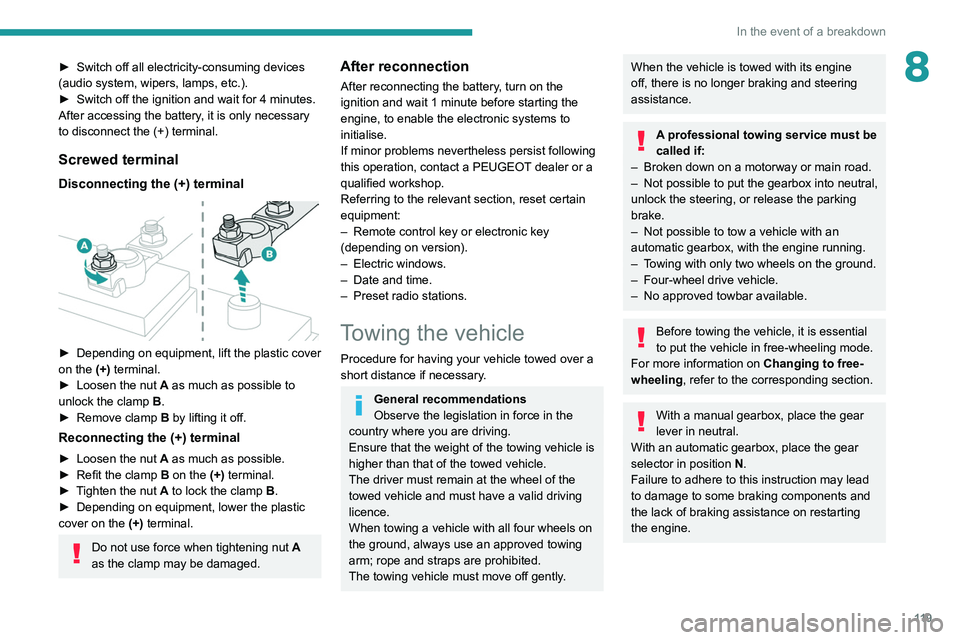
Screwed terminal
Disconnecting the (+) terminal
► Depending on equipment, lift the plastic cover
on the (+) terminal.
►
Loosen the nut
A as much as possible to
unlock the clamp B.
►
Remove clamp
B
by lifting it off.
Reconnecting the (+) terminal
► Loosen the nut A as much as possible.
► Refit the clamp B on the (+) terminal.
►
T
ighten the nut A to lock the clamp B.
►
Depending on equipment, lower the plastic
cover on the
(+) terminal.
Do not use force when tightening nut A
as the clamp may be damaged.
After reconnection
After reconnecting the battery, turn on the
ignition and wait 1 minute before starting the
engine, to enable the electronic systems to
initialise.
If minor problems nevertheless persist following
this operation, contact a PEUGEOT dealer or a
qualified workshop.
Referring to the relevant section, reset certain
equipment:
–
Remote control key or electronic key
(depending on version).
–
Electric windows.
–
Date and time.
–
Preset radio stations.
Towing the vehicle
Procedure for having your vehicle towed over a
short distance if necessary.
General recommendations
Observe the legislation in force in the
country where you are driving.
Ensure that the weight of the towing vehicle is
higher than that of the towed vehicle.
The driver must remain at the wheel of the
towed vehicle and must have a valid driving
licence.
When towing a vehicle with all four wheels on
the ground, always use an approved towing
arm; rope and straps are prohibited.
The towing vehicle must move off gently.
When the vehicle is towed with its engine
off, there is no longer braking and steering
assistance.
A professional towing service must be
called if:
–
Broken down on a motorway or main road.
–
Not possible to put
the gearbox into neutral,
unlock the steering, or release the parking
brake.
–
Not possible to tow a vehicle with an
automatic gearbox, with the engine running.
–
T
owing with only two wheels on the ground.
–
Four-wheel drive vehicle.
–
No approved towbar available.
Before towing the vehicle, it is essential
to put the vehicle in free-wheeling mode.
For more information on Changing to free-
wheeling , refer to the corresponding section.
With a manual gearbox, place the gear
lever in neutral.
With an automatic gearbox, place the gear
selector in position N.
Failure to adhere to this instruction may lead
to damage to some braking components and
the lack of braking assistance on restarting
the engine.