2021 PEUGEOT BOXER spare wheel
[x] Cancel search: spare wheelPage 115 of 212
11 3
Practical information
7Manual gearbox
The gearbox does not require any maintenance (no oil change).
Brake pads
Brake wear depends on the style of
driving, particularly in the case of vehicles
used in town, over short distances. It may be
necessary to have the condition of the brakes
checked, even between vehicle services.
Unless there is a leak in the circuit, a drop in the
brake fluid level indicates that the brake pads
are worn.
If this warning lamp comes on, have the
brake pads checked by a PEUGEOT
dealer or a qualified workshop.
After washing the vehicle, moisture, or in wintry conditions, ice can form on the
brake discs and pads: braking efficiency may
be reduced. Gently dab the brakes to dry and
defrost them.
Brake disc wear
For information on checking brake disc
wear, contact a PEUGEOT dealer or a
qualified workshop.
Manual parking brake
If you notice excessive brake lever travel
or decreased effectiveness, the parking brake must be adjusted, even between two
services.
This system must be checked by a PEUGEOT
dealer or a qualified workshop.
Diesel fuel filter
The Diesel fuel filter is located in the engine
compartment near the brake fluid reservoir.
If this warning lamp comes on, bleed the
filter.
You can also bleed it regularly at each engine oil
change.
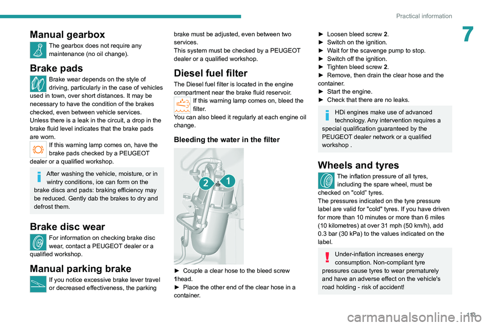
Bleeding the water in the filter
► Couple a clear hose to the bleed screw
1 head.
►
Place the other end of the clear hose in a
container
.
► Loosen bleed screw 2 .
► Switch on the ignition.
►
W
ait for the scavenge pump to stop.
►
Switch off the ignition.
►
T
ighten bleed screw 2.
►
Remove, then drain the clear hose and the
container
.
►
Start the engine.
►
Check that there are no leaks.
HDi engines make use of advanced
technology. Any intervention requires a
special qualification guaranteed by the
PEUGEOT
dealer network or a qualified
workshop .
Wheels and tyres
The inflation pressure of all tyres, including the spare wheel, must be
checked on "cold” tyres.
The pressures indicated on the tyre pressure
label are valid for "cold" tyres. If you have driven
for more than 10 minutes or more than 6 miles
(10 kilometres) at over 31 mph (50
km/h), add
0.3 bar (30 kPa) to the values indicated on the
label.
Under-inflation increases energy
consumption. Non-compliant tyre
pressures cause tyres to wear prematurely
and have an adverse effect on the vehicle's
road holding - risk of accident!
Page 121 of 212
11 9
In the event of a breakdown
8connected to the compressor and the sealant will
not be injected.
If the tyre needs to be deflated, connect hose
I to the tyre valve and press the yellow button
located in the centre of the compressor switch.
Replacing the cartridge
To replace the sealant cartridge, proceed as
follows:
►
Disconnect the hose
I
.
►
T
urn the cartridge to be replaced anti-
clockwise and lift it.
►
Insert the new cartridge and turn it clockwise,
►
Reconnect the hose
I
and connect pipe B to
its location.
The cartridge contains ethylene glycol, which is harmful if swallowed and irritates
the eyes.
It must be kept out of the reach of children.
After use, do not discard the cartridge in standard waste, take it to a
PEUGEOT dealer or an authorised waste
disposal site.
Spare wheel
Parking
► Immobilise the vehicle where it does not
obstruct traffic: the ground must be level, stable
and non-slippery
.
►
In case of sloping or deformed road, place an
object under the wheels to act as a chock.
►
With a manual gearbox, engage first gear
then switch off the ignition to lock the wheels.
►
Apply the parking brake and check that the
indicator lamp lights up on the instrument panel.
►
Y
ou must ensure that the occupants have
exited the vehicle and have moved to a safe
place.
►
Put on your safety vest and indicate that
the vehicle is immobilised using the measures
required by law in the country where you are
driving (warning triangle, hazard warning lamps,
etc.).
►
T
ake out the tools.
Special feature with pneumatic
suspension
If fitted to the vehicle, activate the vehicle lifting
mode before lifting the vehicle with a jack.
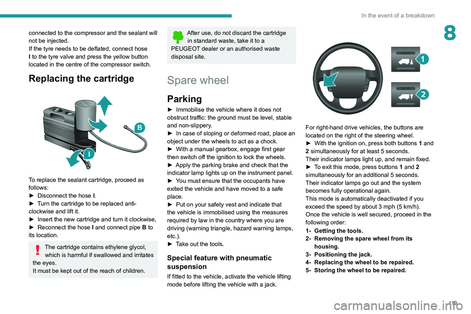
For right-hand drive vehicles, the buttons are
located on the right of the steering wheel.
►
With the ignition on, press both buttons 1
and
2 simultaneously for at least 5 seconds.
Their indicator lamps light up, and remain fixed.
►
T
o exit this mode, press buttons 1 and 2
simultaneously for an additional 5 seconds.
Their indicator lamps go out and the system
becomes fully operational again.
This mode is automatically deactivated if you
exceed the speed by about 3 mph (5 km/h).
Once the vehicle is well secured, proceed in the
following order:
1- Getting the tools.
2- Removing the spare wheel from its housing.
3- Positioning the jack.
4- Replacing the wheel to be repaired.
5- Storing the wheel to be repaired.
Page 122 of 212
120
In the event of a breakdown
1 - Getting the tools
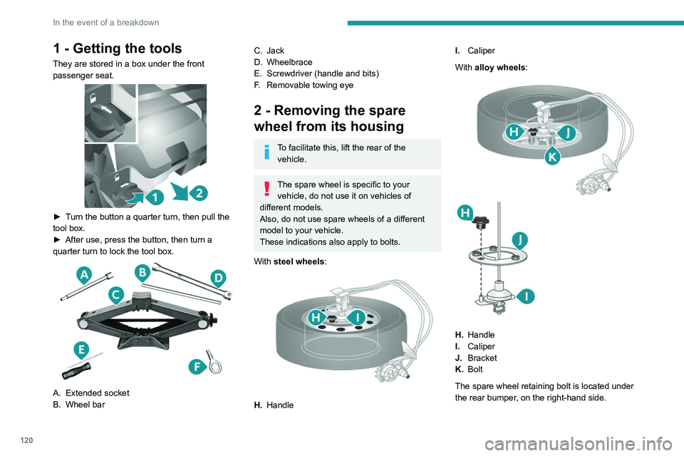
They are stored in a box under the front
passenger seat.
► Turn the button a quarter turn, then pull the
tool box.
►
After use, press the button, then turn a
quarter turn to lock the tool box.
A. Extended socket
B. Wheel bar
C. Jack
D. Wheelbrace
E. Screwdriver (handle and bits)
F. Removable towing eye
2 - Removing the spare
wheel from its housing
To facilitate this, lift the rear of the
vehicle.
The spare wheel is specific to your vehicle, do not use it on vehicles of
different models.
Also, do not use spare wheels of a different
model to your vehicle.
These indications also apply to bolts.
With steel wheels:
H. Handle I.
Caliper
With alloy wheels:
H. Handle
I. Caliper
J. Bracket
K. Bolt
The spare wheel retaining bolt is located under
the rear bumper, on the right-hand side.
Page 123 of 212
121
In the event of a breakdown
8
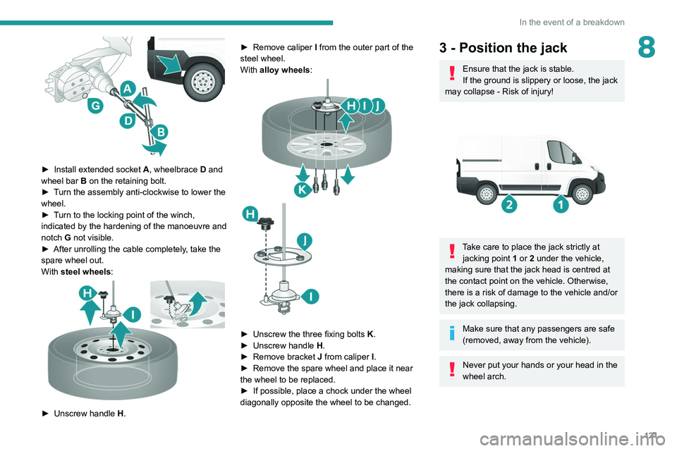
► Install extended socket A , wheelbrace D and
wheel bar B on the retaining bolt.
►
T
urn the assembly anti-clockwise to lower the
wheel.
►
T
urn to the locking point of the winch,
indicated by the hardening of the manoeuvre and
notch G not visible.
►
After unrolling the cable completely
, take the
spare wheel out.
With steel wheels:
► Unscrew handle H . ►
Remove caliper
I
from the outer part of the
steel wheel.
With alloy wheels:
► Unscrew the three fixing bolts K .
► Unscrew handle H
.
►
Remove bracket J
from caliper I.
►
Remove the spare wheel and place it near
the wheel to be replaced.
►
If possible, place a chock under the wheel
diagonally opposite the wheel to be changed.
3 - Position the jack
Ensure that the jack is stable.
If the ground is slippery or loose, the jack
may collapse - Risk of injury!
Take care to place the jack strictly at jacking point 1 or 2 under the vehicle,
making sure that the jack head is centred at
the contact point on the vehicle. Otherwise,
there is a risk of damage to the vehicle and/or
the jack collapsing.
Make sure that any passengers are safe
(removed, away from the vehicle).
Never put your hands or your head in the
wheel arch.
Page 125 of 212
123
In the event of a breakdown
84 - Replacing the wheel to
be repaired
► Remove the wheel trim (depending on
version) by levering it off with screwdriver E
.
►
Loosen the bolts using wheelbrace D
and
bar B.
For more information on Positioning the
jack, refer to the corresponding section.
►
Make sure that the jack is stable and
correctly positioned on the underbody
.
► Using wheelbrace D and bar B, extend the
jack sufficiently to release the wheel.
To clear the wheel easily, a space of about 2 to 3 cm is needed between the
ground and the tyre.
If the wheel is badly punctured/crushed,
increase the space but do not operate the
jack to its maximum lifting position.
► Unscrew the bolts completely and remove the
wheel to be repaired.
►
Make sure that the spare wheel contact
surfaces, the bolts and bolt housings are clean
and free of impurities that could cause the fixing
bolts to become loose.
Do not grease the bolts before screwing
them on: they could unscrew themselves
spontaneously.
► Fit the spare wheel by aligning the 2 holes M
with the 2 corresponding shafts N.
►
Start screwing the bolts on by hand.
Screw on the bolts in this order.
Page 126 of 212
124
In the event of a breakdown
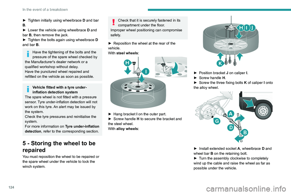
► Tighten initially using wheelbrace D and bar
B.
►
Lower the vehicle using wheelbrace D
and
bar B, then remove the jack.
►
T
ighten the bolts again using wheelbrace D
and bar B.
Have the tightening of the bolts and the
pressure of the spare wheel checked by
the Manufacturer's dealer network or a
qualified workshop without delay.
Have the punctured wheel repaired and
refitted on the vehicle as soon as possible.
Vehicle fitted with a tyre under-
inflation detection system
The spare wheel is not fitted with a pressure
sensor. Tyre under-inflation detection will not
work on this tyre. An alert may be issued by
the system.
Check the tyre pressures and reinitialise the
system.
For more information on Tyre under-inflation
detection, refer to the corresponding section.
5 - Storing the wheel to be
repaired
You must reposition the wheel to be repaired or
the spare wheel under the vehicle to lock the
winch system.
Check that it is securely fastened in its
compartment under the floor.
Improper wheel positioning can compromise
safety.
►
Reposition the wheel at the rear of the
vehicle.
With
steel wheels:
► Hang bracket I on the outer part.
► Screw handle H
to secure the bracket and
the steel wheel.
With alloy wheels:
► Position bracket J on caliper I .
► Screw handle H
.
►
Screw the three fixing bolts
K
of caliper I onto
the alloy wheel.
► Install extended socket A , wheelbrace D and
wheel bar B on the retaining bolt.
►
T
urn the assembly clockwise to completely
wind up the cable and raise the wheel as far as
possible under the vehicle.
Page 195 of 212
193
Alphabetical index
Sensors (warnings) 53
Service indicator
13
Servicing
13, 83
Settings, equipment
15, 21
Sidelamps
23
Silent vehicle warning sound (Electric)
29, 42
Snow chains
103–104
Socket, auxiliary
136, 145
Socket, Jack
136, 145
Sockets, auxiliary
43–45
Speed limiter
83–84
Speed limit recognition
82–83
Speedometer
53
Stability control (ESC)
29
Stability control (ESP)
30
Starting a Diesel engine
69
Station, radio
135, 143
Steering mounted controls, audio
134, 142
Steering wheel adjustment
21
Stickers, customising ~ Stickers,
expressive
89
Stop & Start
23, 31, 26, 33, 76–77, 79, 84, 104
Storage
43–45
Sunshine sensor
23
Super-fast charging (Electric)
102–103, 109
T
Tables of engines 136–137
Table, writing
43–45
Tank, fuel
68
Technical data 136–137
Telephone
137, 177–178
Temperature, coolant
14
Tools
119–124
Topping-up AdBlue®
87
Touch screen
141, 156
Touch screen audio-telematic system
141, 156
Towball, quickly detachable
104–106
Towbar with quickly detachable
towball
104–106
Towed loads
107
Towing another vehicle
104
Traction battery (Electric)
97–98, 109
Traction control (ASR)
57–58
Traffic information (TA)
135
Trip computer
22
Type of bulbs
97
Tyres
85
Tyre under-inflation detection
78–79
U
Under-inflation (detection) 78–79
USB
163–164, 172–173
V
Vehicle data recording and privacy 159
Ventilation
35–36
Voice commands
166–168, 180–182
W
Wallbox (Electric) 71
Warning and indicator lamps
9
Warning lamps
9
Warning lamp, seat belts
60–61
Warnings and indicators
9
Washing
53
Washing (advice)
70, 116–117
Weights
107
Wheel, spare
85, 119–124
Window controls
18
Wipers
26
Wipers, automatic rain sensitive
26