2021 PEUGEOT 508 ESP
[x] Cancel search: ESPPage 188 of 292
186
In the event of a breakdown
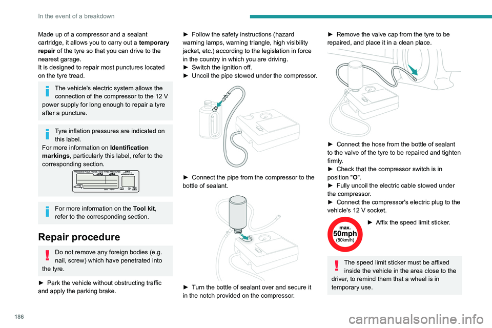
Made up of a compressor and a sealant
cartridge, it allows you to carry out a temporary
repair of the tyre so that you can drive to the
nearest garage.
It is designed to repair most punctures located
on the tyre tread.
The vehicle's electric system allows the connection of the compressor to the 12 V
power supply for long enough to repair a tyre
after a puncture.
Tyre inflation pressures are indicated on this label.
For more information on Identification
markings, particularly this label, refer to the
corresponding section.
For more information on the Tool kit,
refer to the corresponding section.
Repair procedure
Do not remove any foreign bodies (e.g.
nail, screw) which have penetrated into
the tyre.
►
Park the vehicle without obstructing traffic
and apply the parking brake. ►
Follow the safety instructions (hazard
warning lamps, warning triangle, high visibility
jacket, etc.) according to the legislation in force
in the country in which you are driving.
►
Switch the ignition off.
►
Uncoil
the pipe stowed under the compressor.
► Connect the pipe from the compressor to the
bottle of sealant.
► Turn the bottle of sealant over and secure it
in the notch provided on the compressor.
► Remove the valve cap from the tyre to be
repaired, and place it in a clean place.
► Connect the hose from the bottle of sealant
to the valve of the tyre to be repaired and tighten
firmly
.
►
Check that the compressor switch is in
position
"O".
►
Fully uncoil the electric cable stowed under
the compressor
.
►
Connect the compressor's electric plug to the
vehicle's 12
V socket.
► Affix the speed limit sticker .
The speed limit sticker must be affixed
inside the vehicle in the area close to the
driver, to remind them that a wheel is in
temporary use.
Page 190 of 292
188
In the event of a breakdown
Should the pressure of one or more tyres
be adjusted, it is necessary to reinitialise
the under-inflation detection system.
For more information on Tyre under-inflation
detection, refer to the corresponding section.
Spare wheel
Scan the QR Code on page 3 to view
explanatory videos.
For more information on the Tool kit,
refer to the corresponding section.
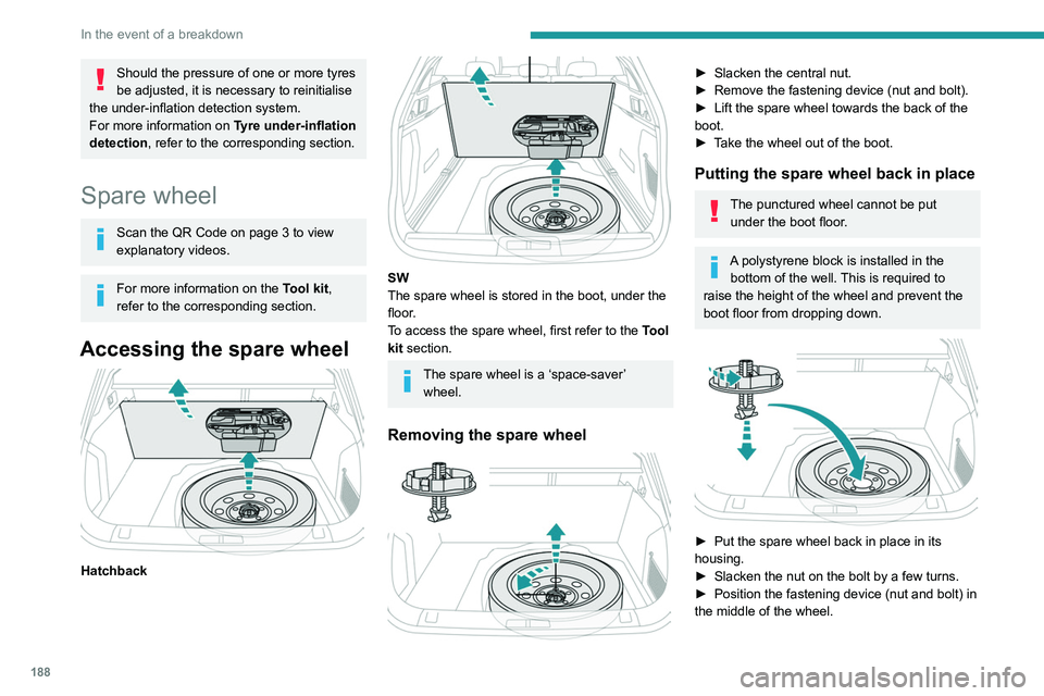
Accessing the spare wheel
Hatchback
SW
The spare wheel is stored in the boot, under the
floor.
To access the spare wheel, first refer to the
Tool
kit
section.
The spare wheel is a ‘space-saver’ wheel.
Removing the spare wheel
► Slacken the central nut.
► Remove the fastening device (nut and bolt).
►
Lift the spare wheel towards the back of the
boot.
►
T
ake the wheel out of the boot.
Putting the spare wheel back in place
The punctured wheel cannot be put under the boot floor.
A polystyrene block is installed in the bottom of the well. This is required to
raise the height of the wheel and prevent the
boot floor from dropping down.
► Put the spare wheel back in place in its
housing.
►
Slacken the nut on the bolt by a few turns.
►
Position the fastening device (nut and bolt) in
the middle of the wheel.
Page 194 of 292

192
In the event of a breakdown
Direction indicators
Rapid flashing of the indicator lamp for a
direction indicator (left or right) indicates
that one of the bulbs on the corresponding
side has failed.
► Turn the connector a quarter turn
anti-clockwise.
► Pull the bulb connector.
► Remove the bulb and replace it.
Amber-coloured bulbs must be replaced
by bulbs with identical specifications and
colour.
Light-emitting diode (LED)
headlamps and lamps
Depending on version, the affected types of
headlamps/lamps are:
–
Full LED technology headlamps.
–
Offset daytime running lamps.
–
Direction indicator side repeaters.
–
Side spotlamps.
–
3D rear lamps.
–
Third brake lamp.
–
Number plate lamps.
If you need to replace this type of bulb,
you must contact a PEUGEOT dealer or
a qualified workshop.
Do not touch the "Full LED" technology
headlamps or lamps - risk of electrocution!
Front lamps
Model with "Full LED" technology
lamps
1. Daytime running lamps / Sidelamps /
Direction indicators
2. Dipped beam headlamps
3. Main beam headlamps
4. Static cornering lamps
Model with halogen lamps
1.Daytime running lamps / Sidelamps (LEDs)
2. Main beam headlamps (H7)
3. Dipped beam headlamps (H7)
4. Direction indicators (PWY24W).
Opening the bonnet/Accessing the
bulbs
Proceed with caution when the engine is hot -
risk of burns!
Take care with objects or clothing that could
be caught in the blades of the cooling fan -
risk of strangulation!
Halogen bulbs (Hx)
To ensure good quality lighting, check
that the bulb is correctly positioned in its
housing.
Page 195 of 292
193
In the event of a breakdown
8Direction indicators
Rapid flashing of the indicator lamp for a
direction indicator (left or right) indicates
that one of the bulbs on the corresponding
side has failed.
► Turn the connector a quarter turn
anti-clockwise.
►
Pull the bulb connector
.
►
Remove the bulb and replace it.
Amber-coloured bulbs must be replaced by bulbs with identical specifications and
colour.
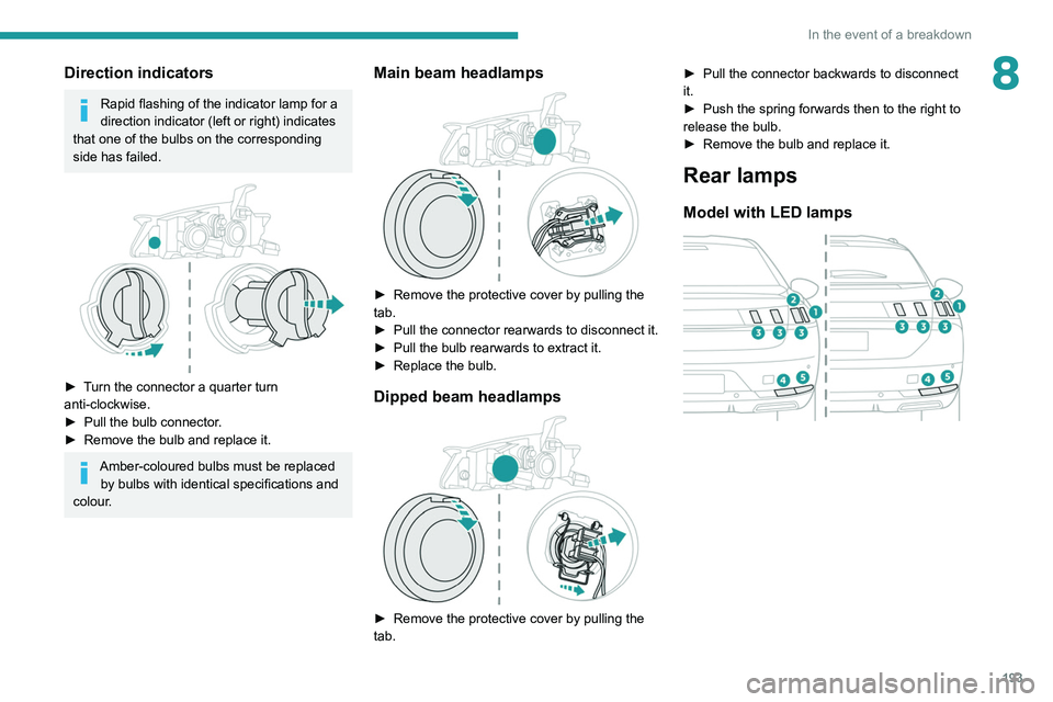
Main beam headlamps
► Remove the protective cover by pulling the
tab.
►
Pull the connector rearwards to disconnect it.
►
Pull the bulb rearwards to extract it.
►
Replace the bulb.
Dipped beam headlamps
► Remove the protective cover by pulling the
tab. ►
Pull the connector backwards to disconnect
it.
►
Push the spring forwards then to the right to
release the bulb.
►
Remove the bulb and replace it.
Rear lamps
Model with LED lamps
Page 196 of 292
194
In the event of a breakdown
Take used remote control batteries and
vehicle batteries to a special collection point.
Protect your eyes and face before
handling the battery.
All operations on the battery must be carried
out in a well ventilated area and away from
naked flames and sources of sparks, to avoid
any risk of explosion or fire.
Wash your hands afterwards.
Accessing the battery
The battery is located under the bonnet.
For access to the (+) terminal:
► Release the bonnet by pulling the internal
release lever, then the external safety catch.
► Raise the bonnet.
(+) Positive terminal.
This terminal has a quick-release clamp.
(-) Negative terminal.
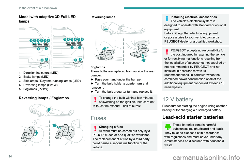
Model with adaptive 3D Full LED
lamps
1. Direction indicators (LED)
2. Brake lamps (LED)
3. Sidelamps / Daytime running lamps (LED)
4. Reversing lamps (P21W)
5. Foglamps (P21W)
Reversing lamps / Foglamps.
Reversing lamps
Foglamps
These bulbs are replaced from outside the rear
bumper.
►
Pass your hand under the bumper
.
►
T
urn the bulb holder a quarter turn and
remove it.
►
T
urn the bulb a quarter turn and replace it.
To change the bulb within a few minutes of switching off the ignition, take care not
to touch the exhaust - risk of burns!
Fuses
Changing a fuse
All work must be carried out only by a
PEUGEOT dealer or a qualified workshop
The replacement of a fuse by a third party
could cause a serious malfunction of the
vehicle.
Installing electrical accessories
The vehicle's electrical system is
designed to operate with standard or optional
equipment.
Before fitting other electrical equipment
or accessories to your vehicle, contact a
PEUGEOT dealer or a qualified workshop.
PEUGEOT accepts no responsibility for
the cost incurred in repairing the vehicle
or for rectifying malfunctions resulting from
the installation of accessories not supplied or
not recommended by PEUGEOT and not
installed in accordance with its
recommendations, in particular when the
combined power consumption of all of the
additional equipment connected exceeds 10
milliamperes.
12 V battery
Procedure for starting the engine using another
battery or for charging a discharged battery.
Lead-acid starter batteries
These batteries contain harmful substances (sulphuric acid and lead).
They must be disposed of in accordance
with regulations and must never under any
circumstances be discarded with household
waste.
Page 203 of 292
201
In the event of a breakdown
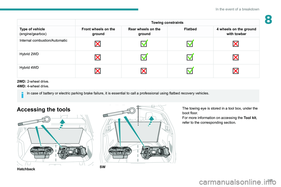
8Towing constraints
Type of vehicle
(engine/gearbox) Front wheels on the
ground Rear wheels on the
ground Flatbed
4 wheels on the ground
with towbar
Internal combustion/Automatic
Hybrid 2WD
Hybrid 4WD
2WD: 2-wheel drive.
4WD: 4-wheel drive.
In case of battery or electric parking brake failure, it is essential to call a p
rofessional using flatbed recovery vehicles.
Accessing the tools
Hatchback
SW The towing eye is stored in a tool box, under the
boot floor.
For more information on accessing the
Tool kit,
refer to the corresponding section.
Page 205 of 292

203
Technical data
9Engine technical data and
towed loads
Engines
The engine characteristics are given in the
vehicle's registration document, as well as in
sales brochures.
Only the values available at the time of
publication are presented in the tables.
Contact a PEUGEOT dealer or a qualified
workshop to obtain missing values.
The maximum power corresponds to the value type-approved on a test bed, under
conditions defined by European legislation
(Directive 1999/99/EC).
For more information, contact a PEUGEOT
dealer or a qualified workshop.
Weights and towed loads
The weights and towed loads relating to
the vehicle are indicated on the registration
document, as well as in sales brochures.
These values are also indicated on the
manufacturer's plate or label.
For more information, contact a PEUGEOT
dealer or a qualified workshop.
The GTW (Gross Train Weight) and towed load
values indicated are valid up to a maximum
altitude of 1,000 metres. The towed load value
must be reduced by 10% for each additional
1,000 metres of altitude.
The maximum authorised nose weight
corresponds to the weight permitted on the
towball.
When exterior temperatures are high, the
vehicle performance may be limited in
order to protect the engine. When the exterior
temperature is higher than 37°C, reduce the
towed weight.
Towing even with a lightly loaded vehicle can adversely affect its road holding.
Braking distances are increased when towing
a trailer.
When using a vehicle to tow, never exceed
a speed of 62 mph (100
km/h) (observe the
local legislation in force).
Page 206 of 292

204
Technical data
Engines and towed loads - Petrol
EnginesPureTech 130 EAT8 THP 150
EAT6THP 165
EAT6 PureTech 180 S&S EAT8
Gearboxes Automatic 8-speed Automatic
6-speedAutomatic
6-speed Automatic 8-speed
Codes EB2ADTS ATN8 Euro
6.3 EP6FDTMD AT6III Euro
5EP6FDTM
AT6III Euro
5EP6FADTXD ATN8 STT
Euro
6.3
Model codes
Hatchback: FP... F3...
SW: FR... F4... HNST
5GXV 5GYV 5GFT
Body styles Hatchback SW Hatchback Hatchback Hatchback SW
Cubic capacity (cc) 1,1991,5981,598 1,598
Max. power: EC standard (kW) 9611 0121 133
Fuel UnleadedUnleaded Unleaded Unleaded
Braked trailer (within the GTW limit) (kg)
on a 10% or 12% gradient 1,330
1,290 6006001,600 1,600
Unbraked trailer (kg) 735745600600745745
Maximum authorised nose weight (kg) 707075757575