2021 PEUGEOT 5008 key
[x] Cancel search: keyPage 127 of 292
125
Driving
6– The electric parking brake is being applied.In these cases, this indicator lamp flashes
for a few seconds, then goes off.
Malfunctions
In the event of a fault with the system, this
warning lamp flashes for a few moments
on the instrument panel, then remains on,
accompanied by the display of a message.
Have it checked by a PEUGEOT dealer or a
qualified workshop.
The vehicle stalls in STOP mode
All of the instrument panel warning lamps come
on if there is a fault.
►
Switch off the ignition then start the engine
again with the key or the " ST
ART/STOP" button.
12 V battery
The Stop & Start system requires a
12 V battery of specific technology and
specification.
All work must be carried out only by a
PEUGEOT
dealer or a qualified workshop.
Tyre under-inflation detection
This system alerts the driver when one or more
tyres have a drop in pressure.
The alert is raised when the vehicle is moving,
not when stationary.
It compares the information given by the wheel
speed sensors with reference values, which
must be reinitialised every time the tyre
pressures are adjusted or a wheel changed.
It takes the last values
stored during
the
reinitialisation request into account. It is
therefore essential that the tyre pressure is
correct during the operation. This operation is
the driver’s responsibility.
The tyre under-inflation detection cannot, in any circumstances, replace the need
for vigilance on the part of the driver.
This system does not avoid the need to
regularly check the tyre pressures (including
the spare wheel), especially before a long
journey.
Driving with under-inflated tyres, particularly
in adverse conditions (heavy load, high
speed, long journey):
–
worsens road-holding.
–
lengthens braking distances.
–
causes premature wear of the tyres.
–
increases energy consumption.
The inflation pressures defined for the vehicle can be found on the tyre pressure
label.
For more information on the Identification
markings, refer to the corresponding section.
Checking tyre pressures
This check should be done monthly
when the tyres are "cold" (vehicle stopped for
1 hour or after a journey of less than 6 miles
(10
km) at moderate speeds).
Otherwise, add 0.3 bar to the pressures
shown on the label.
Snow chains
The system does not have to be
reinitialised after fitting or removing snow
chains.
Under-inflation alert
This is signalled by the fixed illumination of this warning lamp, accompanied by an
audible signal and, depending on equipment, the
display of a message.
►
Reduce speed immediately
, avoid excessive
steering movements and avoid sudden braking.
►
Stop the vehicle as soon as it is safe to do
so.
The loss of pressure detected may not always cause visible deformation of the
tyre.
Do not rely on just a visual check.
►
Using a compressor
, such as the one in
the temporary puncture repair kit, check the
pressures of all four tyres when cold.
►
If it is not possible to carry out this check
immediately
, drive carefully at reduced speed.
Page 170 of 292
168
Practical information
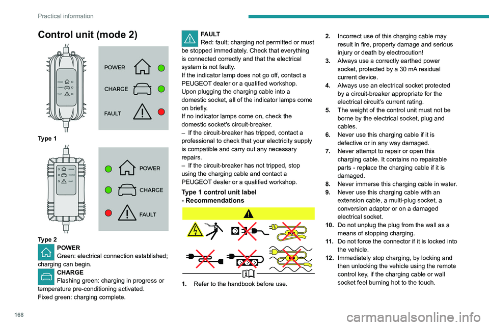
Control unit (mode 2)
Type 1
Type 2POWER
Green: electrical connection established;
charging can begin.
CHARGE
Flashing green: charging in progress or
temperature pre-conditioning activated.
Fixed green: charging complete.
FAULT
Red: fault; charging not permitted or must
be stopped immediately. Check that everything
is connected correctly and that the electrical
system is not faulty.
If the indicator lamp does not go off, contact a
PEUGEOT dealer or a qualified workshop.
Upon plugging the charging cable into a
domestic socket, all of the indicator lamps come
on briefly.
If no indicator lamps come on, check the
domestic socket's circuit-breaker.
–
If the circuit-breaker has tripped, contact a
professional to check that your electricity supply
is compatible and carry out any necessary
repairs.
–
If the circuit-breaker has not tripped, stop
using the charging cable and contact a
PEUGEOT
dealer or a qualified workshop.
Type 1 control unit label
- Recommendations
1. Refer to the handbook before use. 2.
Incorrect use of this charging cable may
result in fire, property damage and serious
injury or death by electrocution!
3. Always use a correctly earthed power
socket, protected by a 30 mA residual
current device.
4. Always use an electrical socket protected
by a circuit-breaker appropriate for the
electrical circuit’s current rating.
5. The weight of the control unit must not be
borne by the electrical socket, plug and
cables.
6. Never use this charging cable if it is
defective or in any way damaged.
7. Never attempt to repair or open this
charging cable. It contains no repairable
parts - replace the charging cable if it is
damaged.
8. Never immerse this charging cable in water.
9. Never use this charging cable with an
extension cable, a multi-plug socket, a
conversion adaptor or on a damaged
electrical socket.
10. Do not unplug the plug from the wall as a
means of stopping charging.
11 . Do not force the connector if it is locked into
the vehicle.
12. Immediately stop charging, by locking and
then unlocking the vehicle using the remote
control key, if the charging cable or wall
socket feel burning hot to the touch.
13.This charging cable includes components
liable to cause electrical arcing or sparks.
Do not expose to flammable vapours.
14. Only use this charging cable with PEUGEOT
vehicles.
15. Never plug the cable into the wall socket (or
unplug it) with wet hands.
Type 2 control unit label
- Recommendations
Refer to the handbook before use.
1.Incorrect use of this charging cable may
result in fire, property damage and serious
injury or death by electrocution!
2. Always use a correctly earthed power
socket, protected by a 30 mA residual
current device.
Page 171 of 292
169
Practical information
713.This charging cable includes components
liable to cause electrical arcing or sparks.
Do not expose to flammable vapours.
14. Only use this charging cable with PEUGEOT
vehicles.
15. Never plug the cable into the wall socket (or
unplug it) with wet hands.
Type 2 control unit label
- Recommendations
Refer to the handbook before use.
1.Incorrect use of this charging cable may
result in fire, property damage and serious
injury or death by electrocution!
2. Always use a correctly earthed power
socket, protected by a 30
mA residual
current device. 3.
Always use an electrical socket protected
by a circuit-breaker appropriate for the
electrical circuit’s current rating.
4. The weight of the control unit must not be
borne by the electrical socket, plug and
cables.
5. Never use this charging cable if it is
defective or in any way damaged.
6. Never attempt to repair or open this
charging cable. It contains no repairable
parts - replace the charging cable if it is
damaged.
7. Never immerse this charging cable in water.
8. Never use this charging cable with an
extension cable, a multi-plug socket, a
conversion adaptor or on a damaged
electrical socket.
9. Do not unplug the plug from the wall as a
means of stopping charging.
10. Immediately stop charging, by locking and
then unlocking the vehicle using the remote
control key, if the charging cable or wall
socket feel burning hot to the touch. 11 .
This charging cable includes components
liable to cause electrical arcing or sparks.
Do not expose to flammable vapours.
12. Only use this charging cable with PEUGEOT
vehicles.
13. Never plug the cable into the wall socket (or
unplug it) with wet hands.
14. Do not force the connector if it is locked into
the vehicle.
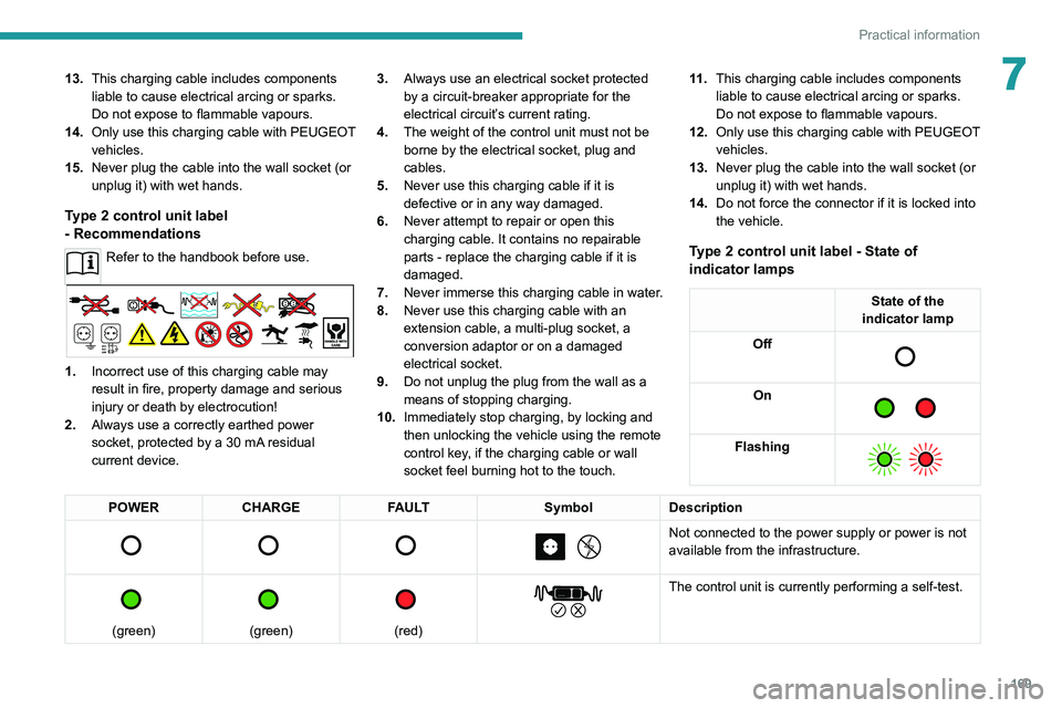
Type 2 control unit label - State of
indicator lamps
State of the
indicator lamp
Off
On
Flashing
POWER CHARGE FAULT SymbolDescription
Not connected to the power supply or power is not
available from the infrastructure.
(green)
(green)
(red)
The control unit is currently performing a self-test.
Page 176 of 292
174
Practical information
Observe the legislation in force in the
country where you are driving.
Vehicle equipped with motorised
tailgate with Hands-Free Access
function
To avoid unintentionally opening the tailgate
while operating the towing device:
–
Deactivate this function in advance in your
vehicle's configuration menu.
–
Or remove the electronic key from the
recognition zone, with the tailgate closed.
Towing device with quickly detachable towball
Presentation
No tools are required to install or remove this
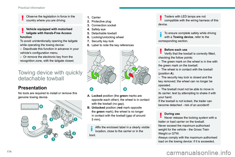
genuine towing device.
1. Carrier
2. Protective plug
3. Connection socket
4. Safety eye
5. Detachable towball
6. Locking/unlocking wheel
7. Security key lock
8. Label to note the key references
A. Locked position (the green marks are
opposite each other); the wheel is in contact
with the towball (no gap).
B. Unlocked position (red mark opposite the green mark); the wheel is no longer
in contact with the towball (gap of around
5
mm).
Affix the enclosed label in a clearly visible location, close to the carrier or in the
boot.
Trailers with LED lamps are not compatible with the wiring harness of this
device.
To ensure complete safety while driving with a Towing device , refer to the
corresponding section.
Before each use
Verify that the towball is correctly fitted,
checking the follow points:
–
The green mark on the wheel is in line with
the green mark on the towball.
–
The wheel is in contact with the towball
(position A
).
–
The security key lock is closed and the
key removed; the wheel can no longer be
operated.
–
The towball must not be able to move in
its carrier; test by attempting to shake it with
your hand.
If the towball is not locked, the trailer can
become detached - risk of an accident!
During use
Never release the locking system with a
trailer or load carrier on the towball.
Never exceed the maximum authorised
weight for the vehicle - the Gross Train
Weight or GTW.
Always comply with the maximum authorised
load on the towing device: if it is exceeded,
this device may become detached from the
vehicle - risk of an accident!
Before driving, check the headlamp height
adjustment and check that the lamps on the
trailer operate correctly.
For more information on Headlamp height
adjustment, refer to the corresponding
section.
After use
When travelling without a trailer or
load carrier, remove the towball and fit the
protective plug into the carrier, to provide
clear visibility of the number plate and/or its
lighting.
Fitting the towball
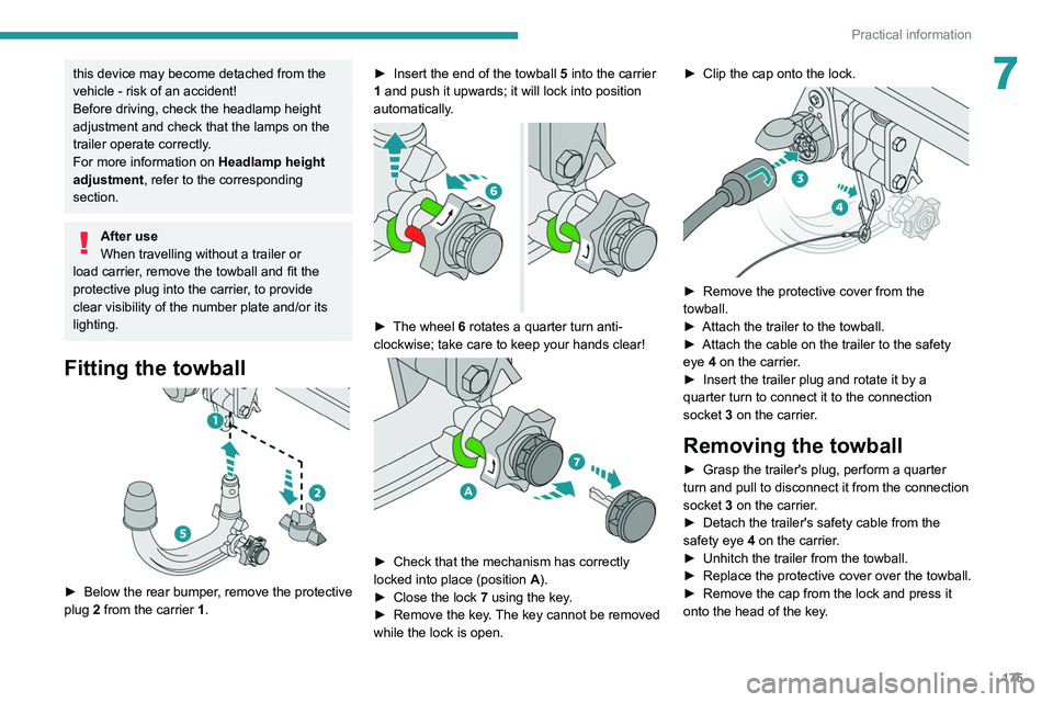
► Below the rear bumper, remove the protective
plug 2 from the carrier 1.
Page 177 of 292
175
Practical information
7this device may become detached from the
vehicle - risk of an accident!
Before driving, check the headlamp height
adjustment and check that the lamps on the
trailer operate correctly.
For more information on Headlamp height
adjustment, refer to the corresponding
section.
After use
When travelling without a trailer or
load carrier, remove the towball and fit the
protective plug into the carrier, to provide
clear visibility of the number plate and/or its
lighting.
Fitting the towball
► Below the rear bumper , remove the protective
plug 2 from the carrier 1. ►
Insert the end of the towball
5 into the carrier
1 and push it upwards; it will lock into position
automatically.
► The wheel 6 rotates a quarter turn anti-
clockwise; take care to keep your hands clear!
► Check that the mechanism has correctly
locked into place (position A
).
►
Close the lock 7
using the key.
►
Remove the key
. The key cannot be removed
while the lock is open. ►
Clip the cap onto the lock.
► Remove the protective cover from the
towball.
►
Attach the trailer to the towball.
►
Attach the cable on the trailer to the safety
eye
4 on the carrier.
►
Insert the trailer plug and rotate it by a
quarter turn to connect it to the connection
socket
3 on the carrier.
Removing the towball
► Grasp the trailer's plug, perform a quarter
turn and pull to disconnect it from the connection
socket
3 on the carrier.
►
Detach the trailer's safety cable from the
safety eye
4 on the carrier.
►
Unhitch the trailer from the towball.
►
Replace the protective cover over the towball.
►
Remove the cap from the lock and press it
onto the head of the key
.
Page 178 of 292
176
Practical information
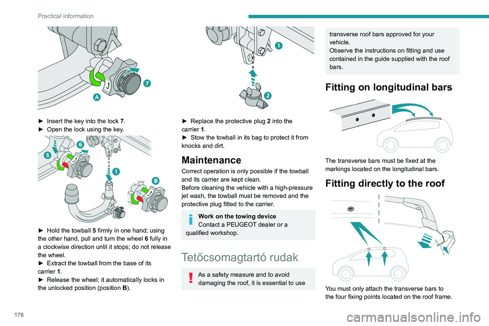
► Insert the key into the lock 7.
► Open the lock using the key .
► Hold the towball 5 firmly in one hand; using
the other hand, pull and turn the wheel 6 fully in
a clockwise direction until it stops; do not release
the wheel.
►
Extract the towball from the base of its
carrier
1.
►
Release the wheel; it automatically locks in
the unlocked position (position B
).
► Replace the protective plug 2 into the
carrier 1.
►
Stow the towball in its bag to protect it from
knocks and dirt.
Maintenance
Correct operation is only possible if the towball
and its carrier are kept clean.
Before cleaning the vehicle with a high-pressure
jet wash, the towball must be removed and the
protective plug fitted to the carrier.
Work on the towing device
Contact a PEUGEOT dealer or a
qualified workshop.
Tetőcsomagtartó rudak
As a safety measure and to avoid damaging the roof, it is essential to use
transverse roof bars approved for your
vehicle.
Observe the instructions on fitting and use
contained in the guide supplied with the roof
bars.
Fitting on longitudinal bars
The transverse bars must be fixed at the
markings located on the longitudinal bars.
Fitting directly to the roof
You must only attach the transverse bars to
the four fixing points located on the roof frame.
These points are concealed by the vehicle doors
when the doors are closed.
The roof bar fixings have a stud which must be
inserted into the opening of each fixing point.
Maximum load distributed over the
transverse roof bars, for a loading height
not exceeding 40 cm (except bicycle carrier):
80 kg.
As this value may change, please verify the
maximum load quoted in the guide supplied
with the roof bars.
If the height exceeds 40 cm, adapt the speed
of the vehicle to the profile of the road to
avoid damaging the roof bars and the fixings
on the vehicle.
Be sure to refer to national legislation in order
to comply with the regulations for transporting
objects that are longer than the vehicle.
Recommendations
Distribute the load uniformly, taking care
to avoid overloading one of the sides.
Arrange the heaviest part of the load as close
as possible to the roof.
Secure the load firmly.
Drive gently: the vehicle will be more
susceptible to the effects of side winds and its
stability may be affected.
Regularly check the security and tight
fastening of the roof bars, at least before each
trip.
Page 188 of 292
186
Practical information
Store AdBlue® out of the reach of
children, in its original container.
Procedure
Before starting the top-up procedure, ensure that
the vehicle is parked on a flat and level surface.
In wintry conditions, ensure that the temperature
of the vehicle is above -11°C. Otherwise the
AdBlue
® may be frozen and so cannot be poured
into the tank. Park the vehicle in a warmer area
for a few hours to allow the top-up to be carried
out.
Never pour the AdBlue® into the Diesel
fuel tank.
If any AdBlue® is splashed, or if there are
any spillages on the bodywork, rinse
immediately with cold water or wipe with a
damp cloth.
If the fluid has crystallised, clean it off using a
sponge and hot water.
Important: in the event of a top-up after
an AdBlue breakdown, you must wait
about 5
minutes before switching on the
ignition, without opening the driver's door,
unlocking the vehicle or bringing the
electronic key into the passenger
compartment.
Switch on the ignition, then wait for 10
seconds before starting the engine. ►
Press the "
START/STOP" button to switch off
the engine.
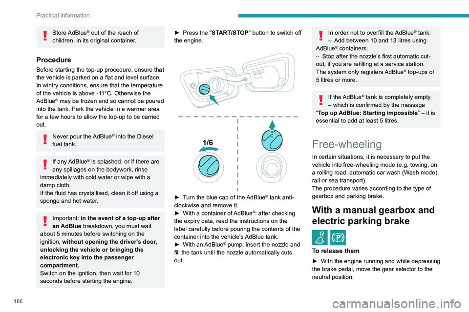
► Turn the blue cap of the AdBlue® tank anti-
clockwise and remove it.
►
With a container of
AdBlue
®: after checking
the expiry date, read the instructions on the
label carefully before pouring the contents of the
container into the vehicle's AdBlue tank.
►
With an
AdBlue® pump: insert the nozzle and
fill the tank until the nozzle automatically cuts
out.
In order not to overfill the AdBlue® tank:
–
Add between 10 and 13 litres using
AdBlue® containers.
–
Stop after the nozzle’ s first automatic cut-
out, if you are refilling at a service station.
The system only registers AdBlue
® top-ups of
5
litres or more.
If the AdBlue® tank is completely empty
– which is confirmed by the message
“Top up
AdBlue: Starting impossible ” – it is
essential to add at least 5 litres.
Free-wheeling
In certain situations, it is necessary to put the
vehicle into free-wheeling mode (e.g. towing, on
a rolling road, automatic car wash (Wash mode),
rail or sea transport).
The procedure varies according to the type of
gearbox and parking brake.
With a manual gearbox and
electric parking brake
/
To release them
► With the engine running and while depressing
the brake pedal, move the gear selector to the
neutral position.
► While depressing the brake pedal, switch off
the ignition.
► Release the brake pedal, then switch on the
ignition again.
► While depressing the brake pedal, press the
control lever to release the parking brake.
► Release the brake pedal, then switch off the
ignition.
Reverting to normal operation
► While depressing the brake pedal, restart the
engine.
With an automatic gearbox
and electric parking brake
/
Release procedure
► With the vehicle stationary and the engine
running, select mode N and switch off the
ignition.
Within 5 seconds:
► Switch on the ignition again.
► While depressing the brake pedal, move the
push selector forwards or backwards to confirm
mode N.
► While depressing the brake pedal, press the
control lever to release the parking brake.
► Release the brake pedal, switch off the
ignition.
Page 189 of 292
187
Practical information
7► While depressing the brake pedal, switch off
the ignition.
►
Release the brake pedal, then switch on the
ignition again.
►
While depressing the brake pedal, press the
control lever to release the parking brake.
►
Release the brake pedal, then switch off the
ignition.
Reverting to normal operation
► While depressing the brake pedal, restart the
engine.
With an automatic gearbox
and electric parking brake
/
Release procedure
► With the vehicle stationary and the engine
running, select mode N and switch off the
ignition.
Within 5
seconds:
►
Switch on the ignition again.
►
While depressing the brake pedal, move the
push selector forwards or backwards to confirm
mode
N.
►
While depressing the brake pedal, press the
control lever to release the parking brake.
►
Release the brake pedal, switch off the
ignition.
If the 5-second time limit is exceeded, the
gearbox engages mode P; it is then necessary to
restart the procedure.
Reverting to normal operation
► While depressing the brake pedal, restart the
engine.
Keyless Entry and Starting
You must not depress the brake pedal
while switching the ignition on again, then
switching it off. If you do, the engine will start,
requiring you to restart the procedure.
Advice on care and maintenance
General recommendations
Observe the following recommendations to avoid
damaging the vehicle.
Exterior
Never use a high-pressure jet wash in
the engine compartment - risk of
damaging the electrical components!
Do not wash the vehicle in bright sunshine or
extremely cold conditions.
When washing the vehicle in an
automatic roller-brush car wash, be sure
to lock the doors and, depending on version,
move the electronic key away and deactivate
the “hands-free” function (Hands-Free
Access).
When using a pressure washer, hold the
lance at least 30 cm from the vehicle
(particularly when cleaning areas containing
chipped paint, sensors or seals).
Promptly clean up any stains containing
chemicals liable to damage the vehicle's paint
(including tree resin, bird droppings, insect
secretions, pollen and tar).
If justified by the environment, clean the
vehicle frequently to remove salty deposits (in
coastal areas), soot (in industrial areas) and
mud (in wet or cold areas). These substances
can be highly corrosive.
Contact a PEUGEOT dealer or a qualified
workshop for advice on removing stubborn
stains requiring special products (such as tar
or insect removers).
Preferably, have paint touch-ups performed
by a PEUGEOT dealer or a qualified
workshop.
Interior
When washing the vehicle, never use a
water hose or high-pressure jet to clean
the interior.
Liquids carried in cups or other open
containers can spill, presenting a risk of
damage to the instruments and controls and