2021 NISSAN TITAN seat memory
[x] Cancel search: seat memoryPage 28 of 638

FRONT POWER CAPTAIN’S CHAIR
SEAT ADJUSTMENT (if so
equipped)
Operating tips
• The power seat motor has an auto-resetoverload protection circuit. If the motor
stops during operation, wait 30 seconds
then reactivate the switch.
• Do not operate the power seat switch for a long period of time when the engine is
off. This will discharge the battery.
For additional information, see “Memory
seat(s)” (P. 3-40).
Forward and backward
Moving the switch as shown will slide the
seat forward or backward to the desired
position.
Reclining
Move the recline switch as shown until the
desired angle is obtained. The reclining feature allows adjustment of
the seatback for occupants of different
sizes for added comfort and to help obtain
proper seat belt fit. For additional informa-
tion, see “Precautions on seat belt usage”
(P. 1-16). Also, the seatback can be reclined
to allow occupants to rest when the vehicle
is stopped and the shif t lever is in P (Park).
LRS2743
1-6Safety-Seats, seat belts and supplemental restraint system
Page 133 of 638

WipersDisplays available wiper options.
Rain Sensor Allows user to turn the rain sensor feature on or off. For additional information, see “Wiper and washer
switch” (P. 2-40).
Speed Dependent Allows user to turn the speed dependent feature on or off. For additional information, see “Wiper and washer
switch” (P. 2-40).
Headlamp On Displays available headlamp on options.
Off Headlights do not activate automatically when the wipers are activated.
Wiper Low & High Headlights activate when the wiper stalk is set to either low or high mode.
Wiper INT, Low & High Headlights activate when the wiper stalk is set to intermittent, low, or high mode.
Memory Seat (ADP) Displays available memory seat options.
Exit Seat Slide Allows the user to turn the exit seat slide on or off. When turned on, this feature will move the driver’s seat
backward for an easy exit when the ignition is turned off and the driver’s door is opened. Af ter getting into
the vehicle and placing the ignition switch in the ACC position, the driver’s seat will move to the previous set
position. For additional information, see “Memory Seat” (P. 3-40).
Exit Steering Up Allows the user to turn the exit steering up feature on or off. When turned on, this feature will move the steer-
ing wheel upward for an easy exit when the ignition is turned off and the driver’s door is opened. Af ter get-
ting into the vehicle and placing the ignition switch in the ACC position, the steering wheel moves to the pre-
vious position. For additional information, see “Memory Seat” (P. 3-40).
Reverse Tilt Mirror Displays reverse tilt mirror information.
Instruments and controls2-27
Page 201 of 638

3 Pre-driving checks and adjustments
Keys.............................................3-2NISSAN Intelligent Key® .......................3-2
NISSAN Vehicle Immobilizer System
keys..........................................3-4
Doors ...........................................3-4
Locking with key .............................3-5
Locking with inside lock knob ................3-6
Locking with power door lock switch .........3-6
Rear doors (King Cab® models) ............... 3-7
Automatic door locks (if so equipped) ........3-8
Child safety rear door lock
(if so equipped) ...............................3-9
NISSAN Intelligent Key® system ..................3-9
Operating range ............................. 3-11
Door locks/unlocks precaution ...............3-11
NISSAN Intelligent Key® Operation ...........3-12
How to use the remote keyless entry
function ..................................... 3-15
Warning signals ............................. 3-19
Troubleshooting guide ......................3-20
Remote Engine Start (if so equipped) ...........3-22
Remote Engine Start operating range .......3-22
Remote starting the vehicle .................3-23
Extending engine run time ..................3-23
Canceling a Remote Engine Start ...........3-23
Conditions the Remote Engine Start will
notwork .................................... 3-24Hood
........................................... 3-25
Fuel-filler door .................................. 3-25
Gasoline fuel engines .......................3-26
Steering wheel ................................. 3-28
Manual operation (if so equipped) ...........3-28
Automatic operation (if so equipped) ........3-29
Sun visors ...................................... 3-30
Vanity mirrors (if so equipped) ...............3-30
Card holder (driver’s side only) ...............3-31
Mirrors ......................................... 3-31
Manual anti-glare rearview mirror
(if so equipped) .............................. 3-31
Automatic anti-glare rearview mirror
(if so equipped) .............................. 3-31
Outside mirrors ............................. 3-32
Truck box ...................................... 3-36
Tailgate ..................................... 3-36
Tie down hooks ............................. 3-40
Memor
y Seat (if so equipped) ..................3-40
Memory storage function ...................3-41
Linking a key fob to a stored memory
position ..................................... 3-41
Entry/exit function .......................... 3-42
System operation ........................... 3-42
Page 204 of 638

NISSAN VEHICLE IMMOBILIZER
SYSTEM KEYS
Additional or replacement keys:
If you still have a key, the key number is not
necessary when you need extra NISSAN
Vehicle Immobilizer System keys. Your ex-
isting key can be duplicated without know-
ing the key number. As many as four
NISSAN Vehicle Immobilizer System keys
can be used with one vehicle. You should
bring all NISSAN Vehicle Immobilizer Sys-
tem keys that you have to the NISSAN
dealer for registration. This is because the
registration process will erase the memory
of all key codes previously registered into
the NISSAN Vehicle Immobilizer System. Af-
ter the registration process, these compo-
nents will only recognize keys coded into
the NISSAN Vehicle Immobilizer System
during registration. Any key that is not
given to the dealer at the time of registra-
tion will no longer be able to start your
vehicle.
CAUTION
Do not allow the immobilizer system
key, which contains an electrical tran-
sponder, to come into contact with wa-
ter or salt water. This could affect sys-
tem function. When the doors are locked using one of the
following methods, the doors cannot be
opened using the inside or outside door
handles. The doors must be unlocked to
open the doors.
WARNING
• Always have the doors locked while
driving. Along with the use of seat
belts, this provides greater safety in
the event of an accident by helping to
prevent persons from being thrown
from the vehicle. This also helps keep
children and others from uninten-
tionally opening the doors, and will
help keep out intruders.
• Before opening any door, always look
for and avoid oncoming traffic.
DOORS
3-4Pre-driving checks and adjustments
Page 229 of 638

AUTOMATIC OPERATION (if so
equipped)
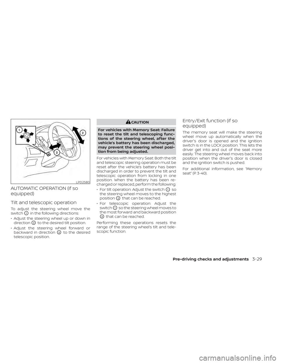
Tilt and telescopic operation
To adjust the steering wheel move the
switch
O1in the following directions:
• Adjust the steering wheel up or down in direction
O2to the desired tilt position.
• Adjust the steering wheel forward or backward in direction
O3to the desired
telescopic position.
CAUTION
For vehicles with Memory Seat: Failure
to reset the tilt and telescoping func-
tions of the steering wheel, af ter the
vehicle’s battery has been discharged,
may prevent the steering wheel posi-
tion from being adjusted.
For vehicles with Memory Seat: Both the tilt
and telescopic steering operation must be
reset af ter the vehicle’s battery has been
discharged in order to prevent the tilt and
telescopic operation from locking in one
position. When the battery has been re-
charged or replaced, perform the following:
• For tilt operation: Adjust the switch
O1so
the steering wheel moves to the highest
position
O2that can be reached.
• For telescopic operation: Adjust the switch
O1so the steering wheel moves to
the most forward and backward position
O3that can be reached.
Performing these operations resets the
range of the steering wheel’s tilt and tele-
scopic function.
Entry/Exit function (if so
equipped)
The memory seat will make the steering
wheel move up automatically when the
driver's door is opened and the ignition
switch is in the LOCK position. This lets the
driver get into and out of the seat more
easily. The steering wheel moves back into
position when the driver's door is closed
and the ignition switch is pushed.
For additional information, see “Memory
seat” (P. 3-40).
LPD2580
Pre-driving checks and adjustments3-29
Page 235 of 638

Power folding outside mirrors
(if so equipped)
CAUTION
Do not manually fold the power folding
mirrors. Manually folding the mirrors
can damage the mirrors.
Push the power folding switch to open or
close the mirrors.
If one of the mirrors are manually operated
or bumped, the mirror body can become
loose at the pivot point. To correct elec-
tronic mirror operation, cycle the mirrors by pushing the power folding switch until the
mirrors are in the open position.
Reverse tilt-down feature (if so
equipped)
The reverse tilt-down feature will turn both
outside mirror surfaces downward to pro-
vide better rear visibility close to the vehicle
when the mirror control switch is in either
the L or R position.
The mirrors automatically return to their
original position when you shif t out of R
(Reverse).
The outside mirror surfaces will return to
their original position when one of the fol-
lowing conditions has occurred:
• The shif t lever is moved to any position
other than R (Reverse).
• The outside mirror control switch is set to the neutral or center position.
• The ignition switch is placed in the OFF position.
NOTE:
If the outside mirror control switch is in
the center position, the mirror surface
will NOT turn downward when the shif t
lever is moved to R (Reverse). For additional information, see “Memory
seat” (P. 3-40).
Automatic anti-glare outside
mirror (if so equipped)
The outside mirror will automatically dim
during nighttime conditions to reduce the
glare from the headlights of trailing ve-
hicles. The automatic anti-glare feature
operates only when the ignition switch is
placed in the ON position.
The automatic anti-glare feature will be on
when starting the vehicle. The indicator
light on the automatic anti-glare rearview
mirror will illuminate when the automatic
anti-glare feature is operating.
To turn off the anti-glare feature, press the
O button on the rearview mirror. The indi-
cator light will turn off.
To turn on the anti-glare feature again,
press the | button on the rearview mirror.
The indicator light will turn on.
For additional information on the auto-
matic anti-glare rearview mirror, see “Auto-
matic anti-glare rearview mirror (if so
equipped)” (P. 3-31).
LPD0417
Pre-driving checks and adjustments3-35
Page 240 of 638

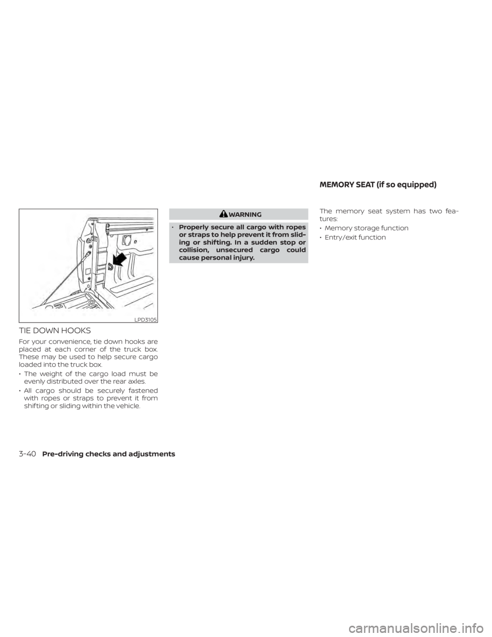
TIE DOWN HOOKS
For your convenience, tie down hooks are
placed at each corner of the truck box.
These may be used to help secure cargo
loaded into the truck box.
• The weight of the cargo load must beevenly distributed over the rear axles.
• All cargo should be securely fastened with ropes or straps to prevent it from
shif ting or sliding within the vehicle.
WARNING
• Properly secure all cargo with ropes
or straps to help prevent it from slid-
ing or shif ting. In a sudden stop or
collision, unsecured cargo could
cause personal injury. The memory seat system has two fea-
tures:
• Memory storage function
• Entry/exit function
LPD3105
MEMORY SEAT (if so equipped)
3-40Pre-driving checks and adjustments
Page 241 of 638

MEMORY STORAGE FUNCTION
Two positions for the driver's seat, steering
column, and outside mirrors (if so
equipped) can be stored in the Memory
Seats. Follow these procedures to set the
memory system.
1. Place the ignition in the ON or ACC posi-tion (the vehicle should be stopped while
setting the memory). 2. Adjust the driver's seat, steering column,
and outside mirrors (if so equipped) to
the desired positions by manually oper-
ating each adjusting switch. For addi-
tional information, see “Seats” (P. 1-2),
“Steering wheel” (P. 3-28) and “Outside
mirrors” (P. 3-32).
3. Push the SET switch and, within 5 sec- onds, push the memory switch (1 or 2).
4. The indicator light for the pushed memory switch will come on and stay
on for approximately 5 seconds.
5. The chime will sound when the memory is stored.NOTE:
If a NEW memory position is stored in the
same memory switch, the previous
memory position will be overwritten by
the new stored position.
Confirming memory storage
• Push the SET switch.
• If a memory position has been stored inthe switch (1 or 2) then the indicator light
for the respective switch will stay on for
approximately 5 seconds.
LINKING A KEY FOB TO A STORED
MEMORY POSITION
Each key fob can be linked to a stored
memory position (memory switch 1 or 2)
with the following procedure.
1. Follow steps 1-3 in the “Memory storage function” section for storing the memory
position.
2. The indicator light for the pushed memory switch will come on. While the
indicator light is on for 5 seconds, press
the
button on the key fob. The haz-
ard lights will flash twice. The indicator
light of the linked memory switch will
blink and click twice. Af ter the indicator
light goes off, the key fob is linked to that
memory setting.
Once it is linked, when the ignition switch is
in the OFF position, pressing the
but-
ton on the key fob will move the driver’s
seat, steering wheel and outside mirrors to
the linked memory switch position.
NOTE:
If a new memory position is stored in the
linked memory switch, then the key fob
will link the new position and overwrites
the previous position.
LPD2302
Pre-driving checks and adjustments3-41