2021 NISSAN TITAN mirror
[x] Cancel search: mirrorPage 155 of 638

Manual headlight aiming control
(if so equipped)
Depending on the number of occupants in
the vehicle and the load it is carrying, the
headlight axis may be higher than desired.
If the vehicle is traveling on a hilly road, the
headlights may directly hit the rearview
mirror of the vehicle ahead or the wind-
shield of the oncoming vehicle. The light
axis can be lowered with the operation of
the switch.
The larger the number designated on the
switch, the lower the axis.When traveling without a heavy load or on a
flat road, select position 0.
Select the switch position by referring to
the following sample.
Vehicle Load
Switch
Position
Driver only or Driver/front passenger 0
Driver/front seat
passenger/rear seat pas- sengers 1
Driver/front seat
passenger/rear seat
passengers/cargo or
driver/cargo/no trailer 2
Fully loaded/no trailer 3
DAYTIME RUNNING LIGHTS (DRL)
SYSTEM (Type A) (if so equipped)
The lights in the fog light area automati-
cally illuminate at 100% intensity when the
engine is started and the parking brake
released. The Daytime Running Lights
(DRL) operate with the headlight switch in
the OFF or AUTO position.
If the parking brake is applied before the
engine is started, the DRL do not illuminate.
The DRL illuminate when the parking brake is released. The DRL remain on while the
engine is running.
It is necessary at dusk to turn the headlight
switch on for interior controls and switches
to illuminate, as those remain off while the
switch is in the OFF position.
WARNING
When the DRL system is active, tail
lights on your vehicle are not on. It is
necessary at dusk to turn on your
headlights. Failure to do so could cause
an accident injuring yourself and oth-
ers.
LED DAYTIME RUNNING LIGHTS
(DRL) SYSTEM (Type B) (if so
equipped)
The LED portion of the headlights auto-
matically illuminates at 100% intensity
when the engine is started and the parking
brake released. The LED Daytime Running
Lights (LED DRL) operate with the headlight
switch in the OFF or AUTO position. When
you turn the headlight switch to the
position for full illumination, the LED lights
switch from LED DRL to the park function.
LIC2230
Instruments and controls2-49
Page 163 of 638

The warning systems switch is used to turn
on and off the following systems that are
activated using the Settings menu in the
vehicle information display:
• Blind Spot Warning (BSW)
• Lane Departure Warning (LDW)
When the warning systems switch is
turned off, the indicator
O1on the switch is
off. The indicator will also be off if all of the
warning systems are deactivated using
the settings menu. The BSW system will turn on the side indi-
cator lights, located by the outside mirrors,
if the radar sensors detect a vehicle in the
detection zone. If the turn signal is acti-
vated in the direction of the detected ve-
hicle, a chime sounds twice and the side
indicator light will flash.
The LDW system will sound a warning; the
steering wheel will vibrate; and the LDW
indicator (orange) will blink to alert the
driver of the vehicle is traveling close to
either the lef t or the right of a traveling lane
with detectable lane markers.
For additional information, see “Blind Spot
Warning (BSW)” (P. 5-32) and “Lane Depar-
ture Warning (LDW)” (P. 5-27).
The vehicle should be driven with the VDC
system on for most driving conditions.
If the vehicle is stuck in mud or snow, the
VDC system reduces the engine output to
reduce wheel spin. The engine speed will
be reduced even if the accelerator is de-
pressed to the floor. If maximum engine
power is needed to free a stuck vehicle,
turn the VDC system off.
To turn off the VDC system, push the VDC
OFF switch. The
indicator will come
on.
LIC2225LIC3344
WARNING SYSTEMS SWITCH VEHICLE DYNAMIC CONTROL (VDC)
OFF SWITCH
Instruments and controls2-57
Page 190 of 638

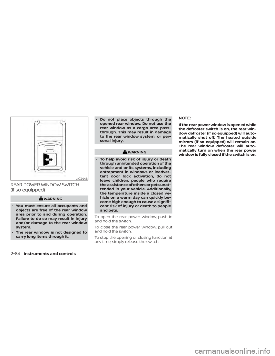
REAR POWER WINDOW SWITCH
(if so equipped)
WARNING
• You must ensure all occupants and
objects are free of the rear window
area prior to and during operation.
Failure to do so may result in injury
and/or damage to the rear window
system.
• The rear window is not designed to
carry long items through it. •
Do not place objects through the
opened rear window. Do not use the
rear window as a cargo area pass-
through. This may result in damage
to the rear window system, or per-
sonal injury.
WARNING
• To help avoid risk of injury or death
through unintended operation of the
vehicle and or its systems, including
entrapment in windows or inadver-
tent door lock activation, do not
leave children, people who require
the assistance of others or pets unat-
tended in your vehicle. Additionally,
the temperature inside a closed ve-
hicle on a warm day can quickly be-
come high enough to cause a signifi-
cant risk of injury or death to people
and pets.
To open the rear power window, push in
and hold the switch.
To close the rear power window, pull out
and hold the switch.
To stop the opening or closing function at
any time, simply release the switch.
NOTE:
If the rear power window is opened while
the defroster switch is on, the rear win-
dow defroster (if so equipped) will auto-
matically shut off. The heated outside
mirrors (if so equipped) will remain on.
The rear window defroster will auto-
matically turn on when the rear power
window is fully closed if the switch is on.
LIC3448
2-84Instruments and controls
Page 201 of 638

3 Pre-driving checks and adjustments
Keys.............................................3-2NISSAN Intelligent Key® .......................3-2
NISSAN Vehicle Immobilizer System
keys..........................................3-4
Doors ...........................................3-4
Locking with key .............................3-5
Locking with inside lock knob ................3-6
Locking with power door lock switch .........3-6
Rear doors (King Cab® models) ............... 3-7
Automatic door locks (if so equipped) ........3-8
Child safety rear door lock
(if so equipped) ...............................3-9
NISSAN Intelligent Key® system ..................3-9
Operating range ............................. 3-11
Door locks/unlocks precaution ...............3-11
NISSAN Intelligent Key® Operation ...........3-12
How to use the remote keyless entry
function ..................................... 3-15
Warning signals ............................. 3-19
Troubleshooting guide ......................3-20
Remote Engine Start (if so equipped) ...........3-22
Remote Engine Start operating range .......3-22
Remote starting the vehicle .................3-23
Extending engine run time ..................3-23
Canceling a Remote Engine Start ...........3-23
Conditions the Remote Engine Start will
notwork .................................... 3-24Hood
........................................... 3-25
Fuel-filler door .................................. 3-25
Gasoline fuel engines .......................3-26
Steering wheel ................................. 3-28
Manual operation (if so equipped) ...........3-28
Automatic operation (if so equipped) ........3-29
Sun visors ...................................... 3-30
Vanity mirrors (if so equipped) ...............3-30
Card holder (driver’s side only) ...............3-31
Mirrors ......................................... 3-31
Manual anti-glare rearview mirror
(if so equipped) .............................. 3-31
Automatic anti-glare rearview mirror
(if so equipped) .............................. 3-31
Outside mirrors ............................. 3-32
Truck box ...................................... 3-36
Tailgate ..................................... 3-36
Tie down hooks ............................. 3-40
Memor
y Seat (if so equipped) ..................3-40
Memory storage function ...................3-41
Linking a key fob to a stored memory
position ..................................... 3-41
Entry/exit function .......................... 3-42
System operation ........................... 3-42
Page 230 of 638

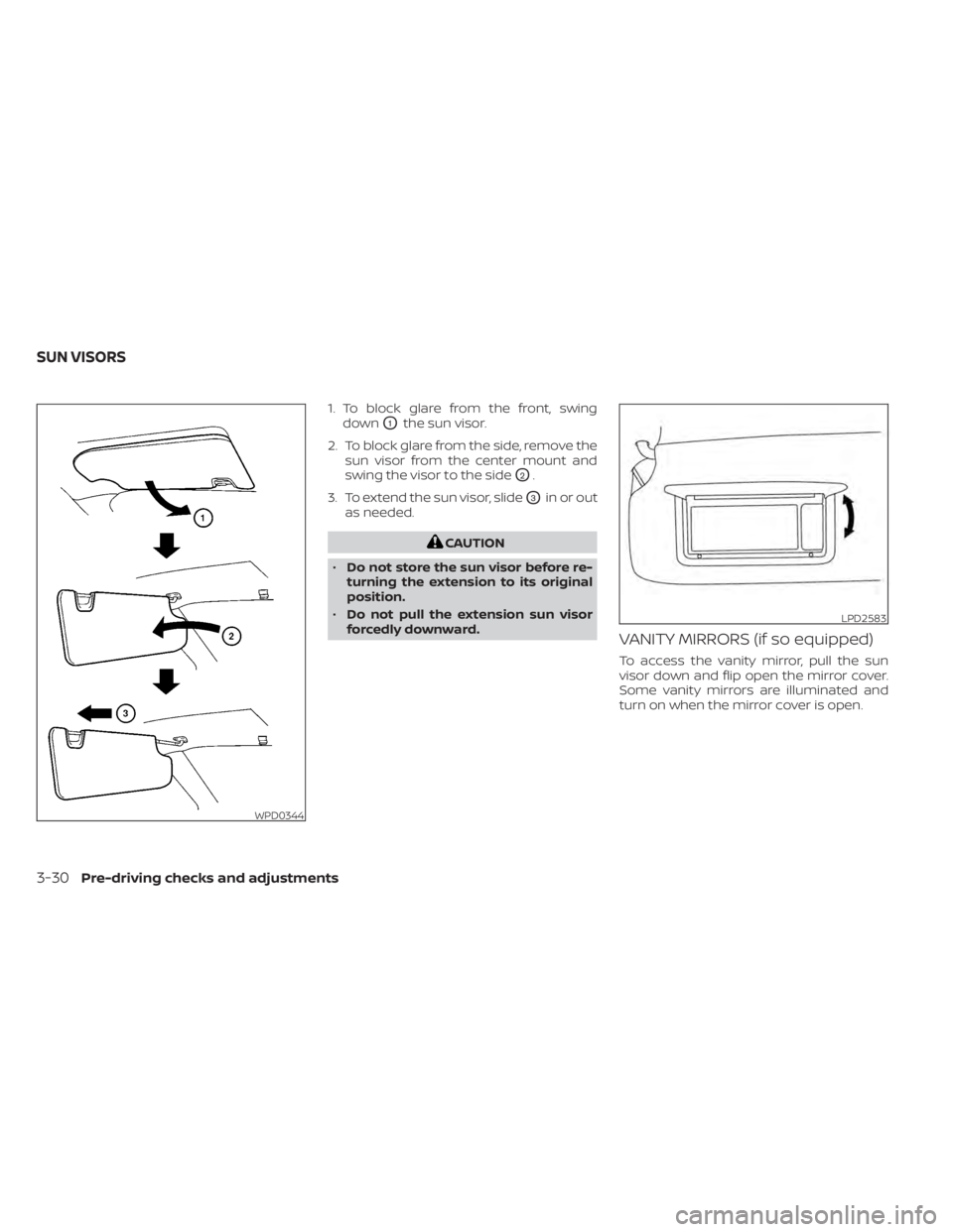
1. To block glare from the front, swingdown
O1the sun visor.
2. To block glare from the side, remove the sun visor from the center mount and
swing the visor to the side
O2.
3. To extend the sun visor, slide
O3in or out
as needed.
CAUTION
• Do not store the sun visor before re-
turning the extension to its original
position.
• Do not pull the extension sun visor
forcedly downward.
VANITY MIRRORS (if so equipped)
To access the vanity mirror, pull the sun
visor down and flip open the mirror cover.
Some vanity mirrors are illuminated and
turn on when the mirror cover is open.
WPD0344
LPD2583
SUN VISORS
3-30Pre-driving checks and adjustments
Page 231 of 638

CARD HOLDER (driver’s side only)
To access the card holder, slide card in the
card holder. Do not view information while
operating the vehicle.
MANUAL ANTI-GLARE REARVIEW
MIRROR (if so equipped)
Use the night positionO1to reduce glare
from the headlights of vehicles behind you
at night.
Use the day position
O2when driving in
daylight hours.
WARNING
Use the night position only when nec-
essary, because it reduces rear view
clarity.
AUTOMATIC ANTI-GLARE
REARVIEW MIRROR (if so equipped)
The inside mirror is designed so that it au-
tomatically dims during night time condi-
tions and according to the intensity of the
headlights of the vehicle following you. The
automatic anti-glare feature is activated
when the ignition switch is in the ON posi-
tion.
LPD2436WPD0126LPD2418
Type A (if so equipped)
MIRRORS
Pre-driving checks and adjustments3-31
Page 232 of 638

NOTE:
Do not hang any objects over the sen-
sors
O1or apply glass cleaner to the sen-
sors. Doing so will reduce the sensitivity
of the sensors, resulting in improper
operation.
The indicator light
O2will illuminate when
the automatic anti-glare feature is operat-
ing.
• To turn off the anti-glare feature, press the O button. The indicator light will
turn off. • To turn on the anti-glare feature, press
the | button again. The indicator light
will turn on.
For additional information on HomeLink®
Universal Transceiver operation, see
“HomeLink® Universal Transceiver” (P. 2-89).
OUTSIDE MIRRORS
WARNING
• Objects viewed in the outside mirror
on the passenger side are closer than
they appear. Be careful when moving
to the right. Using only this mirror
could cause an accident. Use the
inside mirror or glance over your
shoulder to properly judge distances
to other objects.
• Do not adjust the mirrors while driv-
ing. You could lose control of your ve-
hicle and cause an accident.
Manual control type (if so
equipped)
The outside mirrors can be moved in any
direction for a better rear view.
LPD0469
Type B (if so equipped)
LPD2581
3-32Pre-driving checks and adjustments
Page 233 of 638

Electric control type (if so
equipped)
The outside mirror remote control will op-
erate only when the ignition switch is
placed in the ACC or ON position.
Rotate the control dial to select the right or
lef t mirror. Adjust the mirror to the desired
position by moving the control dial.
Return the control dial to the center (neu-
tral) position to prevent accidentally mov-
ing the mirror.
Trailer tow mirrors (if so equipped)
WARNING
Objects viewed in the convex portion of
the trailer tow mirror are closer than
they appear. Be careful when changing
lanes or turning. Using only the convex
mirror could cause an accident. Use the
other mirrors or glance over your
shoulder to properly judge distances to
other objects. Use the outside mirror remote control to
adjust the top portion of the trailer tow
mirror.
The lower portion of the trailer tow mirror
can be moved manually in any direction for
a better rear view.
LPD2606LPD2474
Pre-driving checks and adjustments3-33