Page 417 of 528
TIRE PRESSURE MONITORING
SYSTEM (TPMS)
This vehicle is equipped with TPMS. It moni-
tors tire pressure of all tires except the
spare. When the low tire pressure warning
light is lit, and the “CHECK TIRE PRES” (ve-
hicles without a vehicle information dis-
play) also appears in the trip computer or
the “Tire Pressure Low - Add Air” (vehicles
with a vehicle information display) appears
in the vehicle information display, one or
more of your tires is significantly under-
inflated. If the vehicle is being driven with
low tire pressure, the TPMS will activate and
warn you of it by the low tire pressure warn-
ing light. This system will activate only
when the vehicle is driven at speeds above
16 mph (25 km/h). For additional informa-
tion, refer to “Warning lights, indicator lights
and audible reminders” in the “Instruments
and controls” section, and “Tire Pressure
Monitoring System (TPMS)” in the “Starting
and driving” sections of this manual.
Page 419 of 528
Getting the spare tire and tools
1. Open the trunk and lif t the trunk floorcarpeting.
2. Jack is located beside of the spare tire. To remove, take off the rubber strap and
lif t out.
3. Lif t spacer to access the clamp. 4. Turn the clamp counterclockwise and
remove to release the spare tire.
Removing wheel cover (if so
equipped)
LCE2449LCE2450SCE0630
Page 421 of 528

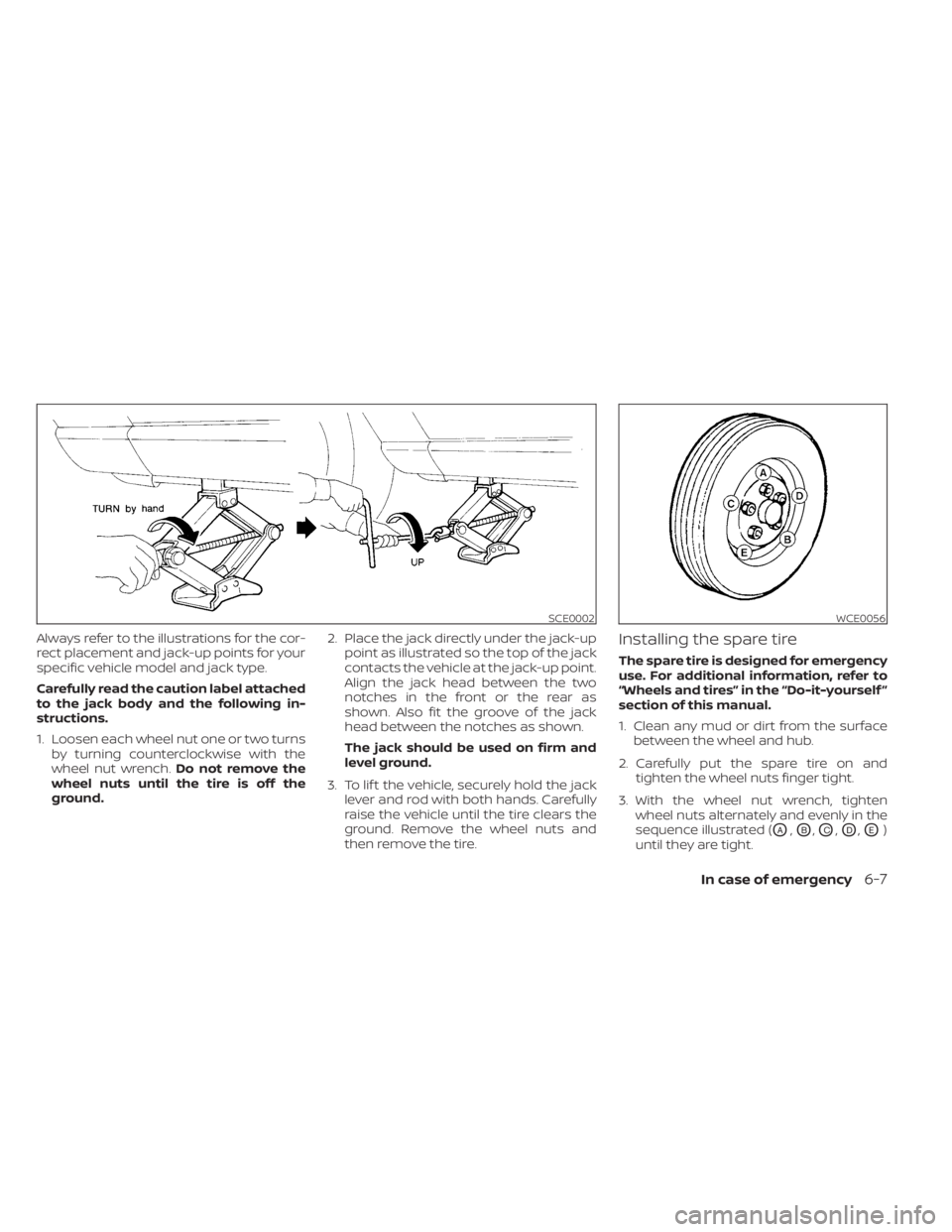
Always refer to the illustrations for the cor-
rect placement and jack-up points for your
specific vehicle model and jack type.
Carefully read the caution label attached
to the jack body and the following in-
structions.
1. Loosen each wheel nut one or two turnsby turning counterclockwise with the
wheel nut wrench. Do not remove the
wheel nuts until the tire is off the
ground. 2. Place the jack directly under the jack-up
point as illustrated so the top of the jack
contacts the vehicle at the jack-up point.
Align the jack head between the two
notches in the front or the rear as
shown. Also fit the groove of the jack
head between the notches as shown.
The jack should be used on firm and
level ground.
3. To lif t the vehicle, securely hold the jack lever and rod with both hands. Carefully
raise the vehicle until the tire clears the
ground. Remove the wheel nuts and
then remove the tire.Installing the spare tire
The spare tire is designed for emergency
use. For additional information, refer to
“Wheels and tires” in the “Do-it-yourself ”
section of this manual.
1. Clean any mud or dirt from the surfacebetween the wheel and hub.
2. Carefully put the spare tire on and tighten the wheel nuts finger tight.
3. With the wheel nut wrench, tighten wheel nuts alternately and evenly in the
sequence illustrated (
OA,OB,OC,OD,OE)
until they are tight.
SCE0002WCE0056
Page 423 of 528
WARNING
• Always make sure that the spare tire
and jacking equipment are properly
secured af ter use. Such items can be-
come dangerous projectiles in an ac-
cident or sudden stop.
• The spare tire is designed for emer-
gency use. Refer to specific instruc-
tions under the heading “Wheels and
tires” in the “Do-it-yourself ” section
of this manual. To start your engine with a booster battery,
the instructions and precautions below
must be followed.
Page 470 of 528

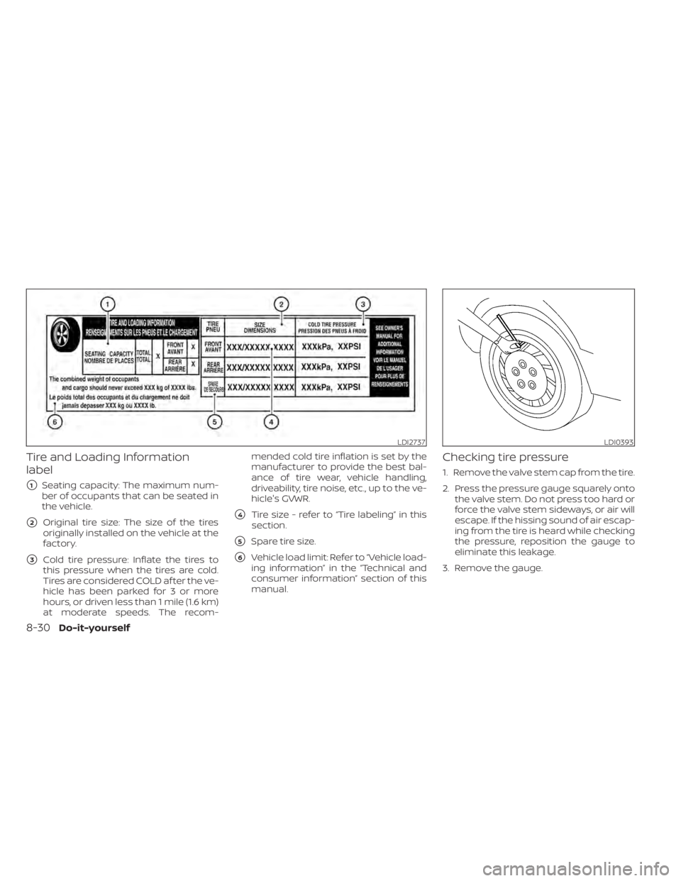
Tire and Loading Information
label
�1Seating capacity: The maximum num-
ber of occupants that can be seated in
the vehicle.
�2Original tire size: The size of the tires
originally installed on the vehicle at the
factory.
�3Cold tire pressure: Inflate the tires to
this pressure when the tires are cold.
Tires are considered COLD af ter the ve-
hicle has been parked for 3 or more
hours, or driven less than 1 mile (1.6 km)
at moderate speeds. The recom- mended cold tire inflation is set by the
manufacturer to provide the best bal-
ance of tire wear, vehicle handling,
driveability, tire noise, etc., up to the ve-
hicle's GVWR.
�4Tire size - refer to “Tire labeling” in this
section.
�5Spare tire size.
�6Vehicle load limit: Refer to “Vehicle load-
ing information” in the “Technical and
consumer information” section of this
manual.
Checking tire pressure
1. Remove the valve stem cap from the tire.
2. Press the pressure gauge squarely onto the valve stem. Do not press too hard or
force the valve stem sideways, or air will
escape. If the hissing sound of air escap-
ing from the tire is heard while checking
the pressure, reposition the gauge to
eliminate this leakage.
3. Remove the gauge.
LDI2737LDI0393
8-30Do-it-yourself
Page 471 of 528

4. Read the tire pressure on the gaugestem and compare to the specification
shown on the Tire and Loading Informa-
tion label.
5. Add air to the tire as needed. If too much air is added, press the core of the valve
stem briefly with the tip of the gauge
stem to release pressure. Recheck the
pressure and add or release air as
needed.
6. Install the valve stem cap.
7. Check the pressure of all other tires, in- cluding the spare.Grades: S, SV, SR
Size Cold Tire Infla- tion Pressure
Front Original
Tire:
205/60R16 230 kPa, 33 PSI
Front Original
Tire:
215/45R18 230 kPa, 33 PSI
Front Original
Tire:
215/50R17 230 kPa, 33 PSI
Rear Original
Tire:
205/60R16 230 kPa, 33 PSI
Rear Original
Tire:
215/45R18 230 kPa, 33 PSI
Rear Original
Tire:
215/50R17 230 kPa, 33 PSI
Spare Tire:
T125/70D16 420 kPa, 60 PSI
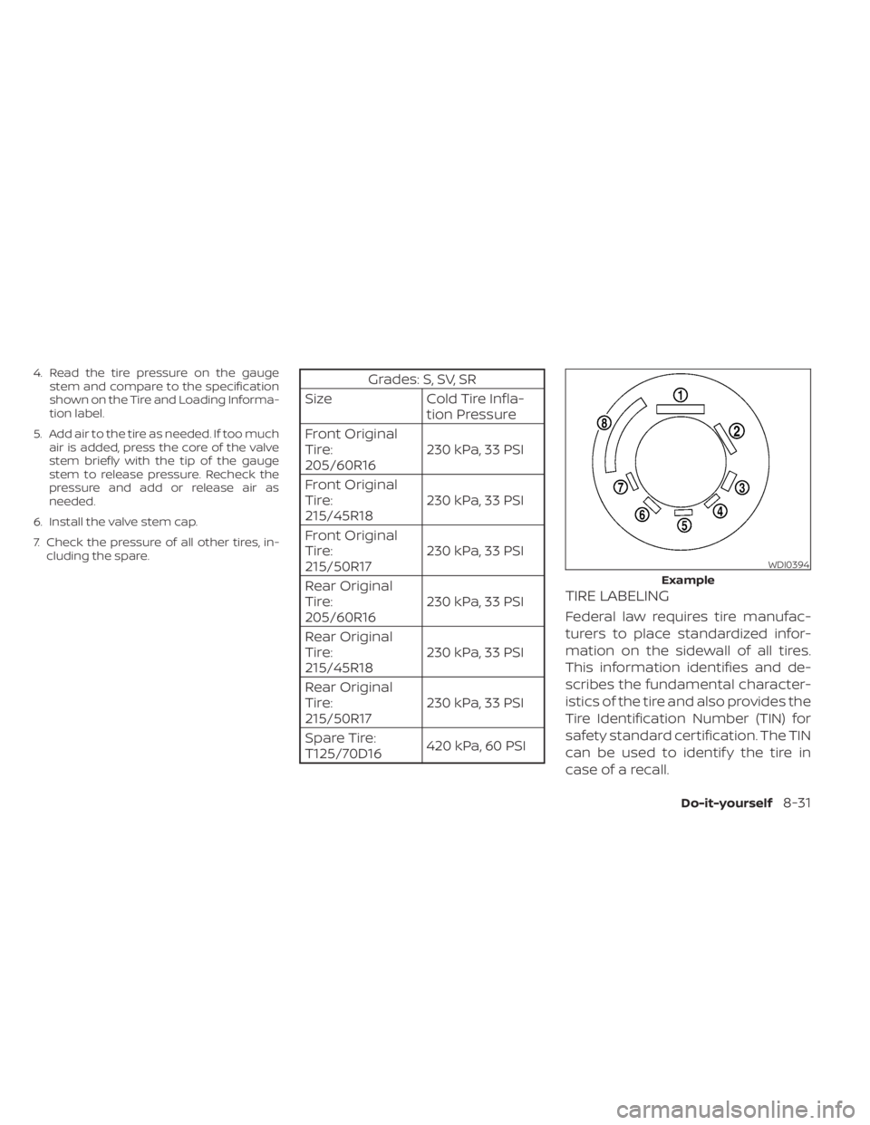
TIRE LABELING
Federal law requires tire manufac-
turers to place standardized infor-
mation on the sidewall of all tires.
This information identifies and de-
scribes the fundamental character-
istics of the tire and also provides the
Tire Identification Number (TIN) for
safety standard certification. The TIN
can be used to identif y the tire in
case of a recall.
WDI0394
Example
Do-it-yourself8-31
Page 476 of 528

CHANGING WHEELS AND TIRES
Tire rotation
NISSAN recommends rotating the tires ev-
ery 7,500 miles (12,000 km).
For additional information on tire replacing
procedures, refer to “Flat tire” in the “In case
of emergency” section of this manual.
As soon as possible, tighten the wheel
nuts to the specified torque with a
torque wrench.Wheel nut tightening torque:
83 f t-lb (113 N·m)
The wheel nuts must be kept tightened
to specifications at all times. It is recom-
mended that wheel nuts be tightened to
specification at each tire rotation inter-
val.
WARNING
• Af ter rotating the tires, check and ad-
just the tire pressure.
• Retighten the wheel nuts when the
vehicle has been driven for 600 miles
(1,000 km) (also in cases of a flat tire,
etc.).
• Do not include the spare tire in the
tire rotation.
• For additional information regarding
tires, refer to “Important Tire Safety
Information” (US) or “Tire Safety In-
formation” (Canada) in the Warranty
Information Booklet.
Tire wear and damage
1. Wear indicator
2. Location mark
WDI0258WDI0259
8-36Do-it-yourself
Page 477 of 528

WARNING
• Tires should be periodically in-
spected for wear, cracking,
bulging or objects caught in
the tread. If excessive wear,
cracks, bulging or deep cuts
are found, the tire(s) should be
replaced.
• The original tires have built-in
tread wear indicators. When
the wear indicators are visible,
the tire(s) should be replaced.
• Tires degrade with age and
use. Have tires, including the
spare, over 6 years old checked
by a qualified technician be-
cause some tire damage may
not be obvious. Replace the
tires as necessary to prevent
tire failure and possible per-
sonal injury. •
Improper service of the spare
tire may result in serious per-
sonal injury. If it is necessary to
repair the spare tire, it is rec-
ommended that you visit a
NISSAN dealer for this service.
• For additional information re-
garding tires, refer to “Impor-
tant Tire Safety Information”
(US) or “Tire Safety Informa-
tion” (Canada) in the Warranty
Information Booklet.
Replacing wheels and tires
When replacing a tire, use the same size,
tread design, speed rating and load carry-
ing capacity as originally equipped. Rec-
ommended types and sizes are shown in
“Wheels and tires” in the “Technical and con-
sumer information” section of this manual.