2021 NISSAN NV200 ignition
[x] Cancel search: ignitionPage 156 of 300
If the ignition switch is placed in the OFF or
ACC position for any reason while the ve-
hicle is in N (Neutral), or any drive position,
the key cannot be turned to the LOCK po-
sition and cannot be removed from the
ignition switch. If this occurs, perform the
following steps:
1. Apply the parking brake when the ve-hicle is stopped.
2. Move the shif t lever to P (Park) to park the vehicle and place the ignition switch
in the LOCK position to remove the key.
P (Park)
CAUTION
To prevent transmission damage, use
the P (Park) position only when the ve-
hicle is completely stopped.
Use the P (Park) shif t lever position when
the vehicle is parked or when starting the
engine. Make sure the vehicle is completely
stopped. The brake pedal must be de-
pressed and the shif t lever button
pressed in to move the shif t lever from N
(Neutral) or any drive position to P (Park).
Apply the parking brake. When parking on a
hill, apply the parking brake first, then place
the shif t lever into the P (Park) position.
R (Reverse)
CAUTION
To prevent transmission damage, use
the R (Reverse) position only when the
vehicle is completely stopped.
Use the R (Reverse) position to back up.
Make sure the vehicle is completely
stopped before selecting the R (Reverse)
position. R (Reverse) speed is limited to 30
mph (48 km/h). Do not exceed 30 mph (48
km/h) in the R (Reverse) position. The
brake pedal must be depressed and the
shif t lever button pressed in to move the
shif t lever from P (Park), N (Neutral) or
any drive position to R (Reverse).
N (Neutral)
Neither forward nor reverse gear is en-
gaged. The engine can be started in this
position. You may shif t to N (Neutral) and
restart a stalled engine while the vehicle is
moving.
D (Drive)
Use this position for all normal forward
driving.
L(Low)
Use this position for engine braking on
steep downhill gradients/climbing steep
slopes and whenever approaching sharp
bends. Do not use the L (Low) position in
any other circumstances.
5-14Starting and driving
Page 158 of 300
Accelerator downshif t
— in D (Drive) position —
For passing or hill climbing, depress the
accelerator pedal to the floor. This shif ts
the transmission down into a lower gear,
depending on the vehicle speed.
High fluid temperature protection
mode
This transmission has a high fluid tem-
perature protection mode. If the fluid tem-
perature becomes too high (for example,
when climbing steep grades in high tem-
peratures with heavy loads, such as when
towing a trailer), engine power and, under
some conditions, vehicle speed will be de-
creased automatically to reduce the
chance of transmission damage. Vehicle
speed can be controlled with the accelera-
tor pedal, but the engine and vehicle speed
may be limited.
Fail-safe
When the fail-safe operation occurs, the
Continuously Variable Transmission will
not be shif ted into the selected driving
position.If the vehicle is driven under extreme
conditions, such as excessive wheel
spinning and subsequent hard braking,
the fail-safe system may be activated.
The Malfunction Indicator Light (MIL)
may come on to indicate the fail-safe
mode is activated. For additional infor-
mation, see “Malfunction Indicator Light
(MIL)” (P. 2-14). This will occur even if all
electrical circuits are functioning prop-
erly. In this case, place the ignition switch
in the OFF position and wait for 10 sec-
onds. Then place the ignition switch
back in the ON position. The vehicle
should return to its normal operating
condition. If it does not return to its nor-
mal operating condition, have the trans-
mission checked and repaired, if neces-
sary. It is recommended that you visit a
NISSAN dealer for this service.
WARNING
When the high fluid temperature pro-
tection mode or fail-safe operation oc-
curs, vehicle speed may be gradually
reduced. The reduced speed may be
lower than other traffic, which could in-
crease the chance of a collision. Be es-
pecially careful when driving. If neces-
sary, pull to the side of the road at a safe
place and allow the transmission to re-
turn to normal operation, or have it re-
paired if necessary.
5-16Starting and driving
Page 164 of 300
•HEADED UPHILL WITH CURBOB:
Turn the wheels away from the curb
and move the vehicle back until the
curb side wheel gently touches the
curb.
• HEADED UPHILL OR DOWNHILL, NO
CURB
OC:
Turn the wheels toward the side of the
road so the vehicle will move away
from the center of the road if it moves.
4. Place the ignition switch in the LOCK position.
Page 168 of 300
When the VDC OFF switch is used to turn off
the system, the VDC system still operates
to prevent one drive wheel from slipping by
transferring power to a non-slipping drive
wheel. The
indicator light flashes if this
occurs. All other VDC functions are off and
the
indicator light will not flash.
The VDC system is automatically reset to
ON when the ignition switch is placed in the
OFF position then back to the ON position.
The computer has a built-in diagnostic fea-
ture that tests the system each time you
start the engine and move the vehicle for-
ward or in reverse at a slow speed. When
the self-test occurs, you may hear a clunk
noise and/or feel a pulsation in the brake
pedal. This is normal and is not an indica-
tion of a malfunction.
indicator light may flash
or theindicator light may
illuminate.
• If brake related parts such as brake
pads, rotors and calipers are not
NISSAN recommended or are ex-
tremely deteriorated, the VDC sys-
tem may not operate properly and
both the
andindicator
lights may illuminate.
• If engine control related parts are not
NISSAN recommended or are ex-
tremely deteriorated, both the
and theindicator lights may
illuminate. •
When driving on extremely inclined
surfaces such as higher banked cor-
ners, the VDC system may not oper-
ate properly and the
indicator
light may flash or theindicator
light may illuminate. Do not drive on
these types of roads.
• When driving on an unstable surface
such as a turntable, ferry, elevator or
ramp, the
indicator light may
flash or theindicator light may
illuminate. This is not a malfunction.
Restart the engine af ter driving onto
a stable surface.
• If wheels or tires other than the
NISSAN recommended ones are
used, the VDC system may not oper-
ate properly and the
indicator
light may flash or theindicator
light may illuminate.
• The VDC system is not a substitute
for winter tires or tire chains on a
snow covered road.
RISE-UP AND BUILD-UP
The system gradually adjusts braking
power during normal braking to help pro-
vide an enhanced brake feel.
5-26Starting and driving
Page 171 of 300
•If your vehicle sustains damage to
the rear bumper fascia, leaving it
misaligned or bent, the sensing zone
may be altered causing inaccurate
measurement of obstacles or false
alarms.
The RSS sounds a tone to warn the driver of
obstacles near the rear bumper when the
ignition is in the ON position and the shif t
lever is in the R (Reverse) position.
RSS SYSTEM OPERATION
The RSS is automatically activated when
the ignition is in the ON position and the
shif t lever is in the R (Reverse) position. The
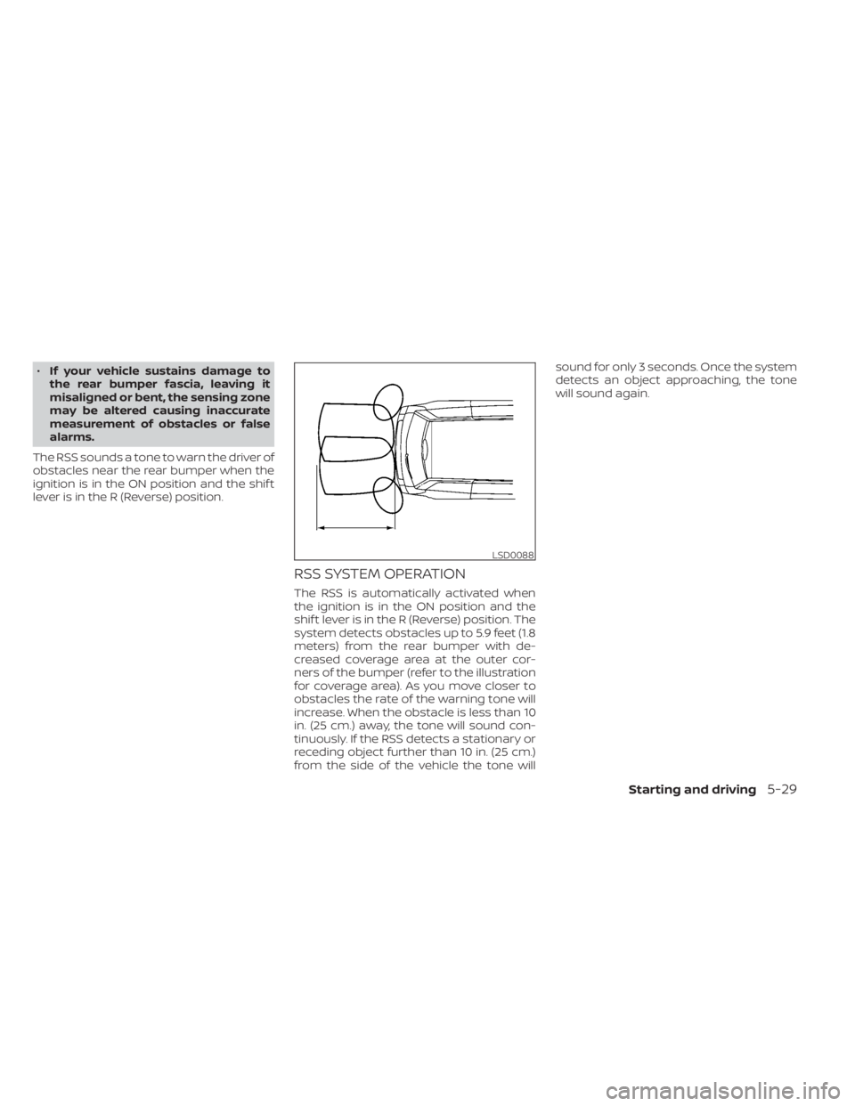
system detects obstacles up to 5.9 feet (1.8
meters) from the rear bumper with de-
creased coverage area at the outer cor-
ners of the bumper (refer to the illustration
for coverage area). As you move closer to
obstacles the rate of the warning tone will
increase. When the obstacle is less than 10
in. (25 cm.) away, the tone will sound con-
tinuously. If the RSS detects a stationary or
receding object further than 10 in. (25 cm.)
from the side of the vehicle the tone will sound for only 3 seconds. Once the system
detects an object approaching, the tone
will sound again.
LSD0088
Page 172 of 300
HOW TO ENABLE/DISABLE THE
RSSThe RSS is automatically activated when
the ignition is in the ON position and the
shif t lever is in the R (Reverse) position.Perform the following steps to enable or
disable the RSS:
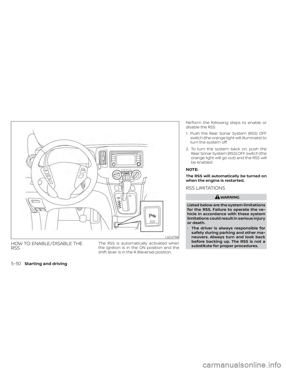
1. Push the Rear Sonar System (RSS) OFF
switch (the orange light will illuminate) to
turn the system off.
2. To turn the system back on, push the Rear Sonar System (RSS) OFF switch (the
orange light will go out) and the RSS will
be enabled.
NOTE:
The RSS will automatically be turned on
when the engine is restarted.
RSS LIMITATIONS
5-30Starting and driving
Page 197 of 300
•Properly position the mats in the
floorwell using the floor mat posi-
tioning hook. For additional informa-
tion, see "Floor mat installation"
(P. 7-5).
• Make sure the floor mat does not in-
terfere with pedal operation.
• Periodically check the floor mats to
make sure they are properly
installed.
• Af ter cleaning the vehicle interior,
check the floor mats to make sure
they are properly installed.
The use of Genuine NISSAN floor mats can
extend the life of your vehicle carpet and
make it easier to clean the interior. Mats
should be maintained with regular clean-
ing and replaced if they become exces-
sively worn.
Floor mat installation
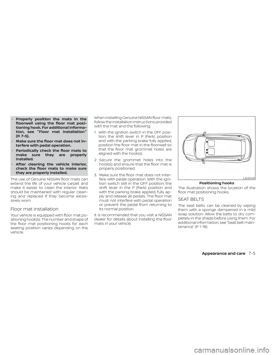
Your vehicle is equipped with floor mat po-
sitioning hook(s). The number and shape of
the floor mat positioning hooks for each
seating position varies depending on the
vehicle. When installing Genuine NISSAN floor mats,
follow the installation instructions provided
with the mat and the following:
1. With the ignition switch in the OFF posi-
tion, the shif t lever in P (Park) position
and with the parking brake fully applied,
position the floor mat in the floorwell so
that the floor mat grommet holes are
aligned with the hook(s).
2. Secure the grommet holes into the hook(s) and ensure that the floor mat is
properly positioned.
3. Make sure the floor mat does not inter- fere with pedal operation. With the igni-
tion switch still in the OFF position, the
shif t lever in the P (Park) position and
with the parking brake applied, fully ap-
ply and release all pedals. The floor mat
must not interfere with pedal operation
or prevent the pedal from returning to
its normal position.
It is recommended that you visit a NISSAN
dealer for details about installing the floor
mats in your vehicle. The illustration shows the location of the
floor mat positioning hooks.
SEAT BELTS
The seat belts can be cleaned by wiping
them with a sponge dampened in a mild
soap solution. Allow the belts to dry com-
pletely in the shade before using them. For
additional information, see “Seat belt main-
tenance” (P. 1-18).
LAI2049
Positioning hooks
Appearance and care7-5
Page 202 of 300
When performing any inspection or main-
tenance work on your vehicle, always take
care to prevent serious accidental injury to
yourself or damage to the vehicle. The fol-
lowing are general precautions which
should be closely observed.CAUTION
• Do not work under the hood while
the engine is hot. Turn the engine off
and wait until it cools down.
• Avoid contact with used engine oil
and coolant. Improperly disposed
engine oil, engine coolant and/or
other vehicle fluids can damage the
environment. Always conform to lo-
cal regulations for disposal of vehicle
fluid.
• Never leave the engine or the Con-
tinuously Variable Transmission
(CVT) related component harness
connector disconnected while the ig-
nition switch is in the ON position.
• Never connect or disconnect the bat-
tery or any transistorized compo-
nent while the ignition switch is in
the ON position.
• DO NOT power wash any interior por-
tion of this vehicle to help minimize
liquid intrusion and potential elec-
tronic component damage.
This “Do-it-yourself ” section gives instruc-
tions regarding only those items which are
relatively easy for an owner to perform.
MAINTENANCE PRECAUTIONS
8-2Do-it-yourself