2021 NISSAN MURANO steering
[x] Cancel search: steeringPage 110 of 508

2.— go back or forward
through the vehicle information menu
items or to change from one display
screen to the next (i.e. trip, TPMS, fuel
economy).
The OK and
buttons also
control audio and control panel functions
in some conditions. Most screens and
menus offer instruction prompts of the
steering switch buttons to indicate how to
control the vehicle information display. An
orange cursor is shown to indicate where
you are in the available menu items. A scroll
bar with up and down arrows will appear if
there is more than one page of menu
items. For additional information, refer to
the separate NissanConnect® Owner’s
Manual.
STARTUP DISPLAY
When the vehicle in placed in the ON or ACC
position the screens that display in the ve-
hicle information display include:
• Home
• Audio
• Navigation (if so equipped)
• Drive computer
• Fuel economy
• Driving aids (if so equipped)
• Speed Limit Sign (if so equipped)
• Tire pressure information
• Warning review
• Settings
The warnings review title screen will show
how many active warnings exist, or “No
items to review” in the event that no warn-
ings are active. For additional information
on warnings and indicators, see “Vehicle
information display warnings and indica-
tors” (P. 2-24).
To control what items display in the vehicle
information display, see “Customize Dis-
play ” (P. 2-20).
SETTINGS
The setting mode allows you to change the
information displayed in the vehicle infor-
mation display:
• Driver Assistance
• Customize Display
• Vehicle Settings
• Maintenance
• Clock
• TPMS Settings
• Unit / Language
• Key-Linked Settings
• Factory Reset
2-18Instruments and controls
Page 114 of 508
Shif t into ParkDoors will unlock when the vehicle is shif ted into P (Park).
Wipers Displays the various wipers settings.
Speed Dependent Allows the user to turn the speed dependent feature on or off.
Driving Position Displays the various driving position settings.
Exit Seat Slide Allows the user to turn the exit seat slide on or off. When turned on, the driver seat will slide back af ter ignition
is turned off for easy exit of the vehicle. For additional information, see "Memory seat" (P. 3-37).
Exit Steering Up Allows the user to turn the exit steering up on or off. When turned on, the steering wheel will rise af ter ignition
is turned off for easy exit of the vehicle. For additional information, see "Memory seat" (P. 3-37).
Remote Engine Start Allows user to turn the Remote Engine Start on or off. When turned on, the engine can be restarted remotely.
For additional information, see “Remote Engine Start” (P. 3-18).
Maintenance
The maintenance menu allows the user to set reminders for various vehicle maintenance items.
WARNING
The tire replacement indicator is not a substitute for regular tire checks, including tire pressure checks. For additional informa-
tion, see “Changing wheels and tires” (P. 8-35). Many factors including tire inflation, alignment, driving habits and road conditions
affect tire wear and when tires should be replaced. Setting the tire replacement indicator for a certain driving distance does not
mean your tires will last that long. Use the tire replacement indicator as a guide only and always perform regular tire checks.
Failure to perform regular tire checks, including tire pressure checks could result in tire failure. Serious vehicle damage could
occur and may lead to a collision, which could result in serious personal injury or death.
Menu item Explanation
Maintenance Displays various maintenance reminder options.
Oil and Filter Allows user to set a reminder at a specific interval or reset the current one.
Tire Allows user to set a reminder at a specific interval or reset the current one.
Other Allows user to set a reminder at a specific interval or reset the current one.
2-22Instruments and controls
Page 116 of 508
VEHICLE INFORMATION DISPLAY
WARNINGS AND INDICATORS
The following messages may appear in
your vehicle information display.
Engine start operation for
Intelligent Key system (if
I-Key battery level is low)
This indicator appears when the battery of
the Intelligent Key is low and when the In-
telligent Key system and the vehicle are not
communicating normally.
If this appears, touch the ignition switch
with the Intelligent Key while depressing
the brake pedal. For additional information,
see “NISSAN Intelligent Key® battery dis-
charge” (P. 5-15).
Key Battery Low
This indicator appears when the Intelligent
Key battery is running out of power.
If this indicator appears, replace the bat-
tery with a new one. For additional infor-
mation, see “Battery replacement” (P. 8-23).
Key ID Incorrect
This warning appears when the ignition
switch is placed from the OFF position and
the Intelligent Key is not recognized by the
system. You cannot start the engine with
an unregistered key.
For additional information, see “NISSAN In-
telligent Key®” (P. 3-7).
Key System Fault See
Owner’s Manual
Af ter the ignition switch is placed in the ON
position, this warning appears for a period
of time and then turns off.
The Key System Fault message warns of a
malfunction with the Intelligent Key sys-
tem. If the warning appears while the en-
gine is stopped, it may be impossible to
start the engine.
If the warning appears while the engine is
running, you can drive the vehicle. However,
in these cases, have the system checked. It
is recommended that you visit a NISSAN
dealer for this service.
No Key Detected
This warning appears when the Intelligent
Key is lef t outside the vehicle with the igni-
tion switch in the ON position. Make sure
the Intelligent Key is inside the vehicle.
For additional information, see “NISSAN In-
telligent Key®” (P. 3-7).
Brightness indicator
This indicator shows the brightness ad-
justment of the instrument panel. For addi-
tional information, see “Instrument bright-
ness control” (P. 2-40).
Rear Door Alert is activated
When the system is enabled, this message
appears when the Rear Door Alert system
is active and can remind the driver to check
the back seat.
• Using the steering wheel switch, a drivercan select “Dismiss Message” to clear the
display for a period of time. If no selection
is made, this message automatically
turns off af ter a period of time.
• Using the steering wheel switch, a driver can select “Disable Alert” to disable the
horn alert for the remainder of the cur-
rent trip.
2-24Instruments and controls
Page 119 of 508
AWD Error: See Owner’s
Manual
This warning appears when the all-wheel
drive system is not functioning properly
while the engine is running.
AWD High Temp. Stop
Vehicle
This warning may appear while trying to
free a stuck vehicle due to increased oil
temperature. The driving mode may
change to 2-Wheel Drive (2WD). If this warn-
ing is displayed, stop the vehicle with the
engine idling, as soon as it is safe to do so.
Then if the warning turns off, you can con-
tinue driving.
Tire Size Incorrect: See
Owner’s Manual
This warning may appear if there is a large
difference between the diameters of the
front and rear wheels. Pull off the road in a
safe area, with the engine idling. Check that
all the tire sizes are the same, that the tire
pressure is correct and that the tires are
not excessively worn.
CVT Error: See Owner's
Manual
This warning appears when the there is a
problem with the CVT system. If this warn-
ing appears, have the system checked. It is
recommended that you visit a NISSAN
dealer for this service.
Alarm - Time for a break?
This indicator appears when the driver en-
ables the timer alert function within the
driver assistance settings and the selected
set time is expired. The time is based on
ignition on time and can be set up to six
hours.
Automatic Emergency
Braking (AEB) with
Pedestrian Detection
emergency warning
indicator
This indicator appears along with an au-
dible warning, when the system detects
the possibility of a forward collision.
For additional information, see “Automatic
Emergency Braking (AEB) with Pedestrian
Detection” (P. 5-87).
Blind Spot Warning (BSW)
and Rear Cross Traffic Alert
(RCTA) indicator
This indicator appears when the BSW and
RCTA systems are engaged.
For additional information, see “Blind Spot
Warning (BSW)” (P. 5-38) and “Rear Cross
Traffic Alert (RCTA)” (P. 5-47).
Cruise control indicator
These indicators show the cruise control
system status.
For additional information, see “Cruise con-
trol” (P. 5-55).
Cruise ON
This message appears if thecruise
control switch on the steering wheel is
pressed and Cruise Control Alerts are en-
abled in the vehicle information display.
For additional information, see “Cruise con-
trol” (P. 5-55).
Cruise Target Speed SET
This message will appear if the Cruise Con-
trol system is on when the SET switch is
pushed and the Cruise Control Alerts are
enabled.
Instruments and controls2-27
Page 120 of 508

For additional information, see “Cruise con-
trol” (P. 5-55).
Currently Unavailable
This message appears when the Vehicle
Dynamic Control (VDC) system is turned
off. The Intelligent Lane Intervention (I-LI)
system will be turned off automatically. For
additional information, see “Vehicle Dy-
namic Control (VDC) system” (P. 5-121) and
“Intelligent Lane Intervention (I-LI)” (P. 5-32).
Driver Attention Alert -
TakeaBreak?
This alert appears when the system has
detected that the driver may be displaying
fatigue or a lack of attention.
Driver Attention Alert
Malfunction
This warning appears when the Intelligent
Driver Alertness (I-DA) system is not function-
ing properly. For additional information, see
“Intelligent Driver Alertness (I-DA)” (P. 5-109).
Forward Driving Aids temporarily
disabled. Front Sensor blocked. See
Owner’s Manual
This message appears when the front ra-
dar sensor may be obstructed due to:
• mud, dirt, snow, ice, etc.• inclement weather (rain, fog, snow, etc.)
All forward driving aids are temporarily dis-
abled until the system detects that the
front radar sensor is no longer obstructed.
For additional information, see:
• Automatic Emergency Braking (AEB) with
Pedestrian Detection (P. 5-87)
• Intelligent Cruise Control (ICC) (P. 5-58)
• Intelligent Forward Collision Warning (I- FCW) (P. 5-97)
Lane Departure Warning
(LDW)/ Intelligent Lane
Intervention (I-LI) indicator
This indicator appears when the LDW
and/or Intelligent Lane Intervention (I-LI)
systems are engaged.
For additional information, see “Lane De-
parture Warning (LDW)” (P. 5-27) and “Intelli-
gent Lane Intervention (I-LI)” (P. 5-32).
Intelligent Cruise Control
(ICC) indicators
These indicators show the Intelligent
Cruise Control (ICC) system status. For ad-
ditional information, see “Intelligent Cruise
Control (ICC)” (P. 5-58).
Intelligent Cruise ON
This message appears if theIntelli-
gent Cruise Control (ICC) switch on the
steering wheel is pressed and Cruise Con-
trol Alerts are enabled in the vehicle infor-
mation display.
For additional information, see “Intelligent
Cruise Control (ICC)” (P. 5-58).
Malfunction See Owner’s Manual
This warning appears when one of the fol-
lowing systems (if so equipped) is not func-
tioning properly:
• Automatic Emergency Braking (AEB) with Pedestrian Detection
• Blind Spot Warning (BSW)
• Intelligent Driver Alertness (I-DA)
• Intelligent Forward Collision Warning (I-FCW)
• Lane Departure Warning (LDW)
• Rear Automatic Braking (RAB)
• Rear Cross Traffic Alert (RCTA)
If one or more of these warning appears,
have the system checked. It is recom-
mended that you visit a NISSAN dealer for
this service.
2-28Instruments and controls
Page 134 of 508
The headlights must be on and the low
beams selected for the fog lights to oper-
ate. The fog lights automatically turn off
when the high beam headlights are
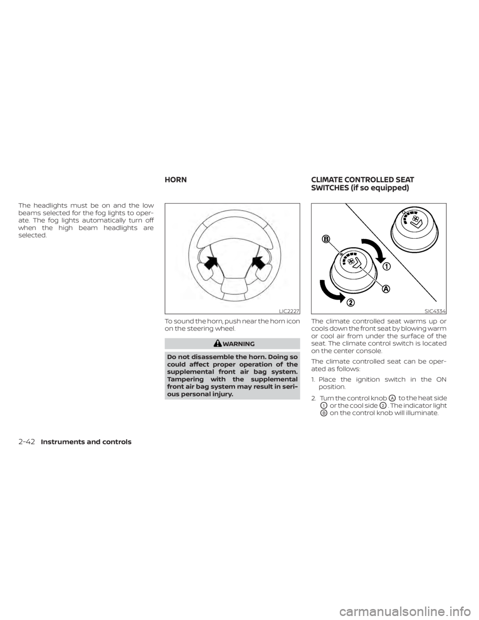
selected.To sound the horn, push near the horn icon
on the steering wheel.
WARNING
Do not disassemble the horn. Doing so
could affect proper operation of the
supplemental front air bag system.
Tampering with the supplemental
front air bag system may result in seri-
ous personal injury. The climate controlled seat warms up or
cools down the front seat by blowing warm
or cool air from under the surface of the
seat. The climate control switch is located
on the center console.
The climate controlled seat can be oper-
ated as follows:
1. Place the ignition switch in the ON
position.
2. Turn the control knob
OAto the heat side
O1or the cool sideO2. The indicator light
OBon the control knob will illuminate.
LIC2227SIC4334
HORN CLIMATE CONTROLLED SEAT
SWITCHES (if so equipped)
2-42Instruments and controls
Page 138 of 508
3. When the seat is warmed or before youleave the vehicle, be sure to turn the
switch off.
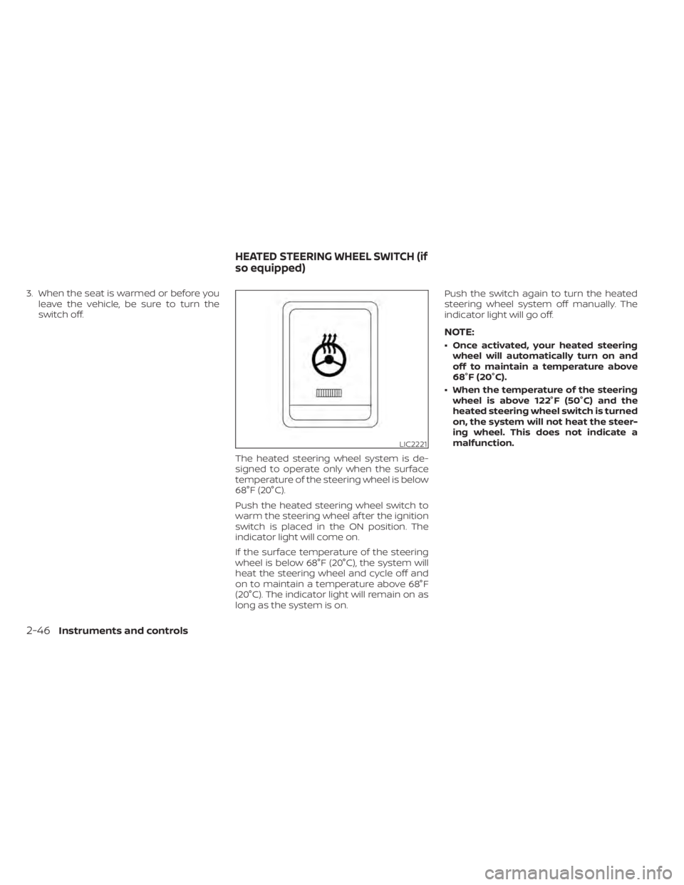
The heated steering wheel system is de-
signed to operate only when the surface
temperature of the steering wheel is below
68°F (20°C).
Push the heated steering wheel switch to
warm the steering wheel af ter the ignition
switch is placed in the ON position. The
indicator light will come on.
If the surface temperature of the steering
wheel is below 68°F (20°C), the system will
heat the steering wheel and cycle off and
on to maintain a temperature above 68°F
(20°C). The indicator light will remain on as
long as the system is on. Push the switch again to turn the heated
steering wheel system off manually. The
indicator light will go off.
NOTE:
• Once activated, your heated steering
wheel will automatically turn on and
off to maintain a temperature above
68°F (20°C).
• When the temperature of the steering wheel is above 122°F (50°C) and the
heated steering wheel switch is turned
on, the system will not heat the steer-
ing wheel. This does not indicate a
malfunction.
LIC2221
HEATED STEERING WHEEL SWITCH (if
so equipped)
2-46Instruments and controls
Page 143 of 508
•Do not use double adapters or more
than one electrical accessory.
• Use power outlets with the engine
running to avoid discharging the ve-
hicle battery.
• Avoid using power outlets when the
air conditioner, headlights or rear
window defroster is on.
• Before inserting or disconnecting a
plug, be sure the electrical accessory
being used is turned off.
• Push the plug in as far as it will go. If
good contact is not made, the plug
may overheat or the internal tem-
perature fuse may open.
• When not in use, be sure to close the
cap. Do not allow water or any other
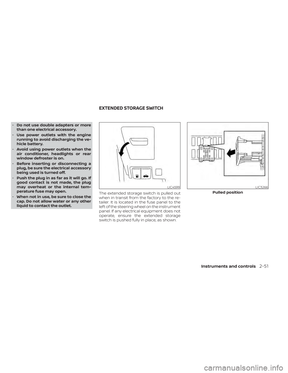
liquid to contact the outlet. The extended storage switch is pulled out
when in transit from the factory to the re-
tailer. It is located in the fuse panel to the
lef t of the steering wheel on the instrument
panel. If any electrical equipment does not
operate, ensure the extended storage
switch is pushed fully in place, as shown.
LIC4599LIC3266
Pulled position
EXTENDED STORAGE SWITCH
Instruments and controls2-51