Page 321 of 492
NISSAN VEHICLE IMMOBILIZER
SYSTEM
The NISSAN Vehicle Immobilizer System
will not allow the engine to start without
the use of the registered key.
If the engine fails to start using a registered
key (for example, when interference is
caused by another registered key, an auto-
mated toll road device or automatic pay-
ment device on the key ring), restart the
engine using the following procedures:
1. Leave the ignition switch in the ON posi-tion for approximately 5 seconds.
2. Place the ignition switch in the OFF or LOCK position, and wait approximately
10 seconds.
3. Repeat steps 1 and 2.
4. Restart the engine while holding the de- vice (which may have caused the inter-
ference) separate from the registered
key.
If the no start condition re-occurs, NISSAN
recommends placing the registered key on
a separate key ring to avoid interference
from other devices. • Make sure the area around the vehicle is
clear.
• Check fluid levels such as engine oil, cool- ant, brake, and windshield-washer fluid
as frequently as possible, or at least
whenever you refuel.
• Check that all windows and lights are clean.
• Visually inspect tires for their appearance and condition. Also check tires for proper
inflation.
• Check that all doors are closed.
• Position seat and adjust head restraints/ headrests.
• Adjust inside and outside mirrors.
• Fasten the seat belt and ask all passen- gers to do likewise.
• Check the operation of warning lights when the ignition switch is placed in the
ON position. For additional information,
refer to “Warning lights, indicator lights
and audible reminders” in the “Instru-
ments and controls” section of this
manual. 1. Apply the parking brake.
2. Move the shif t lever to P (Park) or N (Neu-
tral). P (Park) is recommended.
The starter is designed not to operate
unless the shif t lever is in either P
(Park) or N (Neutral).
3. Push the ignition switch to the ON posi- tion. Depress the brake pedal and push
the ignition switch to start the engine.
To start the engine immediately, push
and release the ignition switch while de-
pressing the brake pedal with the igni-
tion switch in any position.
• If the engine is very hard to start in extremely cold weather or when re-
starting, depress the accelerator
pedal a little (approximately 1/3 to the
floor) and while holding, crank the en-
gine. Release the accelerator pedal
when the engine starts.
• If the engine is very hard to start be- cause it is flooded, depress the accel-
erator pedal all the way to the floor
and hold it. Push the ignition switch to
the ON position to start cranking the
engine. Af ter 5 or 6 seconds, stop
cranking by pushing the ignition
switch to the LOCK position. Af ter
BEFORE STARTING THE ENGINE STARTING THE ENGINE
Starting and driving5-13
Page 340 of 492
The power assisted steering uses a hy-
draulic pump, driven by the engine, to as-
sist steering.
If the engine stops or the drive belt breaks,
you will still have control of the vehicle.
However, much greater steering effort is
needed, especially in sharp turns and at
low speeds.
Page 356 of 492
Getting the spare tire and tools
(Crew Cab models)
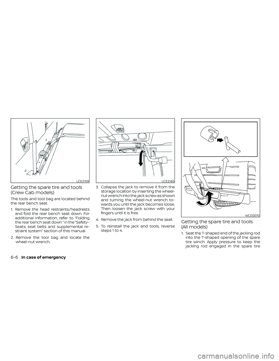
The tools and tool bag are located behind
the rear bench seat.
1. Remove the head restraints/headrestsand fold the rear bench seat down. For
additional information, refer to “Folding
the rear bench seat down ” in the “Safety–
Seats, seat belts and supplemental re-
straint system” section of this manual.
2. Remove the tool bag and locate the wheel-nut wrench. 3. Collapse the jack to remove it from the
storage location by inserting the wheel-
nut wrench into the jack screw as shown
and turning the wheel-nut wrench to-
wards you until the jack becomes loose.
Then loosen the jack screw with your
fingers until it is free.
4. Remove the jack from behind the seat.
5. To reinstall the jack and tools, reverse steps 1 to 4.
Getting the spare tire and tools
(All models)
1. Seat the T-shaped end of the jacking rodinto the T-shaped opening of the spare
tire winch. Apply pressure to keep the
jacking rod engaged in the spare tire
LCE2159LCE2165
WCE0070
6-6In case of emergency
Page 374 of 492
•Properly position the mats in the
floorwell using the floor mat posi-
tioning hook. For additional informa-
tion, refer to "Floor mat installation"
in this section.
• Make sure the floor mat does not in-
terfere with pedal operation.
• Periodically check the floor mats to
make sure they are properly
installed.
• Af ter cleaning the vehicle interior,
check the floor mats to make sure
they are properly installed.
The use of Genuine NISSAN floor mats can
extend the life of your vehicle carpet and
make it easier to clean the interior. Mats
should be maintained with regular clean-
ing and replaced if they become exces-
sively worn.
Floor mat installation
Your vehicle is equipped with floor mat po-
sitioning hook(s). The number and shape of
the floor mat positioning hooks for each
seating position varies depending on the
vehicle. When installing Genuine NISSAN floor mats,
follow the installation instructions provided
with the mat and the following:
1. With the ignition in the OFF position, the
shif t lever in P (Park) position and with
the parking brake fully applied, position
the floor mat in the floorwell so that the
floor mat grommet holes are aligned
with the hook(s).
2. Secure the grommet holes into the hook(s) and ensure that the floor mat is
properly positioned.
3. Make sure the floor mat does not inter- fere with pedal operation. With the igni-
tion still in the OFF position, the shif t le-
ver in the P (Park) position and with the
parking brake applied, fully apply and re-
lease all pedals. The floor mat must not
interfere with pedal operation or prevent
the pedal from returning to its normal
position.
It is recommended that you visit a NISSAN
dealer for details about installing the floor
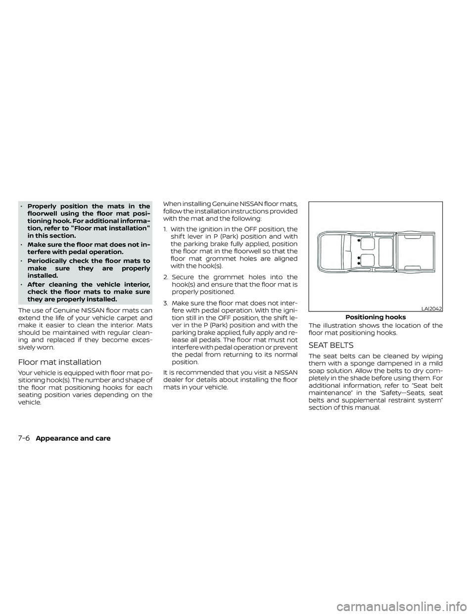
mats in your vehicle. The illustration shows the location of the
floor mat positioning hooks.
SEAT BELTS
The seat belts can be cleaned by wiping
them with a sponge dampened in a mild
soap solution. Allow the belts to dry com-
pletely in the shade before using them. For
additional information, refer to “Seat belt
maintenance” in the “Safety—Seats, seat
belts and supplemental restraint system”
section of this manual.
LAI2042
Positioning hooks
Page 375 of 492
WARNING
Do not allow wet seat belts to roll up in
the retractor. NEVER use bleach, dye or
chemical solvents to clean the seat
belts, since these materials may se-
verely weaken the seat belt webbing.MOST COMMON FACTORS
CONTRIBUTING TO VEHICLE
CORROSION
Most vehicle corrosion is caused by:
• The accumulation of moisture-retaining dirt and debris in body panel sections,
cavities, and other areas.
• Damage to paint and other protective coatings caused by gravel and stone
chips or minor traffic collisions.
ENVIRONMENTAL FACTORS
INFLUENCE THE RATE OF
CORROSION
Moisture
Accumulation of sand, dirt and water on
the vehicle body underside can accelerate
corrosion. Wet floor coverings will not dry
completely inside the vehicle and should
be removed for drying to avoid floor panel
corrosion.
Relative humidity
Corrosion will be accelerated in areas of
high relative humidity, especially those ar-
eas where the temperatures stay above
freezing and where atmospheric pollution
exists and road salt is used.
Temperature
High temperatures accelerate the rate of
corrosion to those parts which are not well
ventilated.
Air pollution
Industrial pollution, the presence of salt in
the air in coastal areas, or heavy road salt
use accelerates the corrosion process.
Road salt also accelerates the disintegra-
tion of paint surfaces.
PROTECT YOUR VEHICLE FROM
CORROSION
• Wash and wax your vehicle of ten to keepthe vehicle clean.
• Always check for minor damage to the paint and repair it as soon as possible.
• Keep drain holes at the bottom of the doors open to avoid water accumulation.
• Check the underbody for accumulation of sand, dirt or salt. If present, wash with
water as soon as possible.
CORROSION PROTECTION
Appearance and care7-7
Page 379 of 492
VQ38DD engine
1. Windshield-washer fluid reservoir
2. Fuse/Fusible link box
3. Fuse/Fusible link box
4. Fuse box
5. Engine oil filler cap
6. Engine oil dipstick
7. Brake fluid reservoir
8. Air cleaner
9. Drive belt location
10. Power steering fluid reservoir
11. Radiator cap
12. Battery
13. Engine coolant reservoir
LDI3520
ENGINE COMPARTMENT CHECK
LOCATIONS
Do-it-yourself8-3
Page 391 of 492
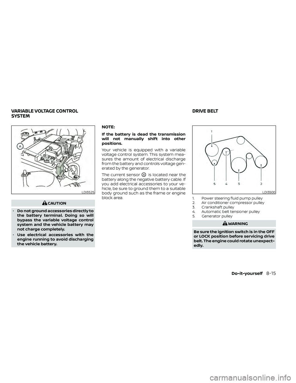
CAUTION
• Do not ground accessories directly to
the battery terminal. Doing so will
bypass the variable voltage control
system and the vehicle battery may
not charge completely.
• Use electrical accessories with the
engine running to avoid discharging
the vehicle battery.
NOTE:
If the battery is dead the transmission
will not manually shif t into other
positions.
Your vehicle is equipped with a variable
voltage control system. This system mea-
sures the amount of electrical discharge
from the battery and controls voltage gen-
erated by the generator.
The current sensor
OAis located near the
battery along the negative battery cable. If
you add electrical accessories to your ve-
hicle, be sure to ground them to a suitable
body ground such as the frame or engine
block area.
1. Power steering fluid pump pulley
2. Air conditioner compressor pulley
3. Crankshaf t pulley
4. Automatic belt tensioner pulley
5. Generator pulley
LDI3500
VARIABLE VOLTAGE CONTROL
SYSTEM DRIVE BELT
Do-it-yourself8-15
Page 392 of 492
1. Visually inspect the belt for signs of un-usual wear, cuts, fraying or looseness. If
the belt is in poor condition or is loose,
have it replaced or adjusted. It is recom-
mended that you visit a NISSAN dealer
for this service.
2. Have the belt checked regularly for con- dition and tension in accordance with
the maintenance schedule found in the
"Maintenance and schedules" section of
this manual.
REPLACING SPARK PLUGS
Iridium-tipped spark plugs
It is not necessary to replace iridium-
tipped
OAspark plugs as frequently as con-
ventional type spark plugs because they
last much longer. Follow the maintenance
log shown in the "Maintenance and sched-
ules" section of this manual. Do not service
iridium-tipped spark plugs by cleaning or
regapping.
• Always replace spark plugs with rec-
ommended or equivalent ones. If replacement is required, it is recom-
mended that you visit a NISSAN dealer for
this service.
SDI1895
SPARK PLUGS