2021 NISSAN ARMADA key
[x] Cancel search: keyPage 204 of 603
3-22Pre-driving checks and adjustments
WARNING
.Always be sure the liftgate has
been closed securely to prevent it
from opening while driving.
. Do not drive with the liftgate
open. This could allow dangerous
exhaust gases to be drawn into
the vehicle. See “Exhaust gas
(carbon monoxide)” (P.5-4).
. Do not leave children unattended
inside the vehicle. They could
unknowingly activate switches
or controls. Unattended children
could become involved in serious
accidents.
. Always be sure that hands and
feet are clear of the door frame to
avoid injury while closing the
liftgate.
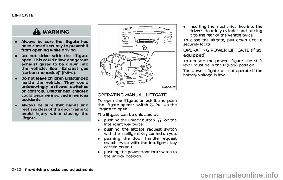
WAD0268X
OPERATING MANUAL LIFTGATE
To open the liftgate, unlock it and push
the liftgate opener switch. Pull up the
liftgate to open.
The liftgate can be unlocked by:
. pushing the unlock button
on the
Intelligent Key twice.
. pushing the liftgate request switch
with the Intelligent Key carried on you.
. pushing the door handle request
switch twice with the Intelligent Key
carried on you.
. pushing the power door lock switch to
the unlock position. .
inserting the mechanical key into the
driver’s door key cylinder and turning
it to the rear of the vehicle twice.
To close the liftgate, pull down until it
securely locks.
OPERATING POWER LIFTGATE (if so
equipped)
To operate the power liftgate, the shift
lever must be in the P (Park) position.
The power liftgate will not operate if the
battery voltage is low.
LIFTGATE
Page 205 of 603
SPA2547
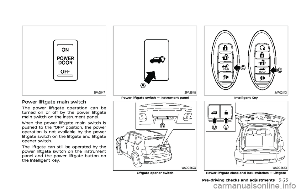
Power liftgate main switch
The power liftgate operation can be
turned on or off by the power liftgate
main switch on the instrument panel.
When the power liftgate main switch is
pushed to the “OFF” position, the power
operation is not available by the power
liftgate switch on the liftgate and liftgate
opener switch.
The liftgate can still be operated by the
power liftgate switch on the instrument
panel and the power liftgate button on
the Intelligent Key.
SPA2548
Power liftgate switch — Instrument panel
WAD0269XLiftgate opener switch
JVP0214X
Intelligent Key
WAD0266XPower liftgate close and lock switches — Liftgate
Pre-driving checks and adjustments3-23
Page 206 of 603

3-24Pre-driving checks and adjustments
Power open
When the liftgate is fully closed, the
liftgate will fully open automatically by:
.pushing the power liftgate switch
on the instrument panel
. pushing the liftgate opener switch
.pushing the power liftgate buttonon the Intelligent Key for more than 1
second
The hazard flashes 4 times and the out-
side chime sounds when the liftgate
starts opening.
NOTE:
The liftgate can be opened by the
power liftgate switch
, the liftgate
opener switchor the power liftgate
buttoneven if the liftgate is
locked. The liftgate will individually un-
lock and open.
Power close
When the liftgate is fully opened, the
liftgate will fully close automatically by:
. pushing the power liftgate switch
on the instrument panel
. pushing the power liftgate button
on the Intelligent Key for more than 1
second
. pushing the power liftgate close
switch
on the lower part of the
liftgate The hazard flashes 4 times and the out-
side chime sounds when the liftgate
starts closing.
NOTE:
When the liftgate is closed, it remains
unlocked. Manually lock the liftgate.
Power close and lock
When the liftgate is fully opened and the
Intelligent Key is carried with you near the
liftgate, the liftgate will fully close and lock
automatically by pushing the power lift-
gate lock switch
on the lower part of
the liftgate.
The hazard flashes 4 times and the out-
side chime sounds when the liftgate
starts closing.
Reverse function
The power liftgate will reverse immedi-
ately if one of the following actions is
performed during power open or power
close.
. pushing the power liftgate switch
on the instrument panel
. pushing the power liftgate button
on the Intelligent Key.
. pushing the power liftgate close
switch
on the lower part of the
liftgate
The outside chime sounds when the
liftgate starts to reverse.
Auto reverse function
The auto-reverse function enables the
liftgate to automatically reverse when
something is caught in the liftgate as it
is opening or closing. When the control
unit detects an obstacle, the liftgate will
reverse and return to the full open or full
close position.
If a second obstacle is detected, the
liftgate motion will stop and the drive
motor will disengage. The liftgate will
enter the manual mode.
A pinch sensor is mounted on each side
of the liftgate. If an obstacle is detected
by the pinch sensor during power close,
the liftgate will reverse and return to the
full open position immediately.
NOTE:
If the pinch sensor is damaged or
removed, the power close function will
not operate.
WARNING
There is a small distance immedi-
ately before the closed position that
cannot be detected. Make sure that
all passengers keep their hands, etc.,
clear from the liftgate opening be-
fore closing the liftgate.
Page 223 of 603

switch in the LOCK position.
The driver’s seat and steering wheel will
return to the previous positions when the
ignition switch is pushed to the ACC
position.
The driver’s seat will not return to the
previous positions if the seat or steering
adjusting switch is operated when the
seat is at the exit position.
Cancel or activate entry/exit func-
tion
The shift lever must be in the P (Park)
position with the ignition switch in the
OFF position.
The entry/exit function can be activated
or canceled by pressing and holding the
SET switch for more than 10 seconds.
The entry/exit function can be canceled
through “Vehicle settings” in the vehicle
information display by performing the
following:
.Switch the “Exit Seat Slide” ON to OFF.
For additional information, refer to
“Vehicle settings” (P.2-23).
. Switch the “Exit Steering Up” ON to
OFF. For additional information, refer
to “Vehicle settings” (P.2-23).
Initialize entry/exit function
If the battery cable is disconnected, or if
the fuse opens, the entry/exit function
will not work though this function was set
on before. In such a case, after connect-
ing the battery or replacing with a new
fuse, open and close the driver’s door
more than two times after the ignition
switch is turned from the ON position to
the LOCK position. The entry/exit func-
tion will be activated.
MEMORY STORAGE
Two positions for the driver’s seat, steer-
ing column and outside mirrors can be
stored in the memory switch. Follow
these procedures to use the memory
system.
1. Move the shift lever to the P (Park)
position.
2. Adjust the driver’s seat, steering col- umn and outside mirrors to the de-
sired positions by manually operating
each adjusting switch. For additional
information, see “Seats” (P.1-3) and
“Tilt/telescopic steering” (P.3-29) and
“Outside mirrors” (P.3-38).
3. Push the SET switch and, within 5 seconds, push the memory switch (1
or 2) fully for at least 1 second.
The indicator light for the pushed
memory switch will stay on for ap- proximately 5 seconds after pushing
the switch.
When the memory is stored in the
memory switch (1 or 2), a buzzer will
sound.
If memory is stored in the same
memory switch, the previous memory
will be deleted.
Linking Intelligent Key to a stored
memory position
The Intelligent Key can be linked to a
stored memory position with the follow-
ing procedure.
1. Follow the steps for storing a memory
position.
2. While the indicator light for the mem- ory switch being set is illuminated for
5 seconds, push the
button on the
Intelligent Key. If the indicator light
blinks, the Intelligent Key is linked to
that memory setting.
Push the ignition switch to the OFF
position, and then push the
button
on the Intelligent Key. The driver’s seat,
steering wheel and outside mirrors will
move to the memorized position.
Pre-driving checks and adjustments3-41
Page 224 of 603

3-42Pre-driving checks and adjustments
Confirming memory storage
.Push the ignition switch to the ON
position and push the SET switch. If
the main memory has not been
stored, the indicator light will come
on for approximately 0.5 second.
When the memory has stored in posi-
tion, the indicator light will stay on for
approximately 5 seconds.
. If the battery cable is disconnected, or
if the fuse opens, the memory will be
canceled. In this case, reset the de-
sired position using the previous pro-
cedure.
. If optional Intelligent Keys are added
to your vehicle, the memory storage
procedure to switch 1 or 2 and linking
Intelligent Key procedure to a stored
memory position should be per-
formed again for each Intelligent Key.
For additional Intelligent Key informa-
tion, see “Keys” (P.3-2).
Selecting the memorized position
1. Move the shift lever to the P (Park)
position.
2. Use one of the following methods to move the driver’s seat, the outside
mirrors and the steering wheel.
.Push the memory switch (1 or 2)fully for at least 1 second. The driver’s seat, steering column and
outside mirrors will move to the
memorized position or to the exit
position when the entry/exit function
is set to active with the indicator light
flashing, and then the light will stay on
for approximately 5 seconds.
SETTING MEMORY FUNCTION
The status of the following settings can
be linked to the Intelligent Key and the
memorized settings can be available for
each Intelligent Key.
.
Air conditioner system
. Navigation system (if so equipped)
. Audio system
To use the memory function, lock the
doors with the Intelligent Key that is
linked to the settings.
To enable the memorized settings:
1. Carry the Intelligent Key that is linked to the settings, and unlock the doors
by pushing the driver’s door handle
request switch or “UNLOCK”
but-
ton on the Intelligent Key.
2. Place the ignition switch in the ON position. “Connection with the key has
been done” will be displayed on the
screen and the memorized settings
are available (only when a new Intel-
ligent Key is used).
SYSTEM OPERATION
The memory seat system will not work or
will stop operating under the following
conditions:
.When the vehicle speed is above 0
MPH (0 km/h) or 4 MPH (7 km/h) for
some limited functions such linking an
Intelligent Key to the vehicle when the
power source is turned on from off or
during the Exit function.
. When any of the memory switches are
pushed while the memory seat is
operating.
. When the adjusting switch for the
driver’s seat and steering column is
turned on while the memory seat is
operating.
. When the seat has already been
moved to the memorized position.
. When no seat position is stored in the
memory switch.
. When the shift lever is moved from the
P (Park) position to any other position.
Page 225 of 603
4 Monitor, heater, air conditioner, audio,phone and voice recognition systems
NissanConnect® Owner’s Manual .................................... 4-2
Safety note ........................................................................\
................ 4-2
RearView Monitor (if so equipped) ................................. 4-3
RearView Monitor system operation ..................... 4-4
How to read the displayed lines ................................ 4-4
Difference between predictive and
actual distances ...................................................................... 4-5
How to park with predictive course lines .......... 4-6
RearView Monitor settings ............................................. 4-8
RearView Monitor system limitations .................... 4-8
System maintenance .......................................................... 4-9
Intelligent Around View® Monitor (if
so equipped) ........................................................................\
.......... 4-10
Intelligent Around View® Monitor
system operation ................................................................ 4-11
Intelligent Around View® Monitor settings ...... 4-19
Intelligent Around View® Monitor
system limitations .............................................................. 4-21
System maintenance ....................................................... 4-23
Camera aiding sonar function (models with
Intelligent Around View® Monitor) ............................... 4-24 Sonar system operation ................................................ 4-24
Turning on and off the sonar function ............. 4-25
Sonar function settings ................................................. 4-26 Sonar system limitations ........................................... 4-28
System maintenance .................................................... 4-28
Moving Object Detection (MOD) ................................... 4-29
MOD system operation ................................................ 4-30
Turning on and off the MOD system ............... 4-31
MOD function settings ................................................. 4-32
MOD system limitations .............................................. 4-32
System maintenance .................................................... 4-33
Ventilators ........................................................................\
.............. 4-34 Center ventilators ............................................................ 4-34
Side ventilators .................................................................. 4-34
Rear ventilators .................................................................. 4-34
Heater and air conditioner ................................................ 4-35
Automatic air conditioner ......................................... 4-36
Rear automatic air conditioning system ....... 4-38
Operating tips ..................................................................... 4-41
Linking Intelligent Key (if so equipped) ........... 4-41
In-cabin microfilter .......................................................... 4-41
Servicing air conditioner ............................................. 4-41
Antenna ........................................................................\
.................... 4-41 Window antenna ............................................................... 4-41
Satellite antenna ............................................................... 4-42
Car phone or CB radio ......................................................... 4-42
Page 232 of 603
4-8Monitor, heater, air conditioner, audio, phone and voice recognition systems
5. When the vehicle is parked in thespace completely, place the shift lever
in the P (Park) position and apply the
parking brake.
REARVIEW MONITOR SETTINGS
The RearView Monitor settings can be
changed using the following procedure.
1. Push the MENU button on the DisplayCommander.
2. Touch the “Settings” key on the touch screen display.
3. Touch the “Camera” key. Available setting items:
Setting items
Action
Predictive Course Lines Display the predictive course lines.
Display
Settings Brightness
Adjust display settings by touching the “+”/“-” key.
Contrast
Tint
Color
Black Level
REARVIEW MONITOR SYSTEM LIM-
ITATIONS
WARNING
Listed below are the system limita-
tions for RearView Monitor. Failure to
operate the vehicle in accordance
with these system limitations could
result in serious injury or death.
. The system cannot completely
eliminate blind spots and may
not show every object.
. Underneath the bumper and the
corner areas of the bumper can-
not be viewed on the RearView
Monitor because of its monitoring
range limitation. The system will
not show small objects below the
bumper, and may not show ob-
jects close to the bumper or on the ground.
. Objects viewed in the RearView
Monitor differ from actual dis-
tance because a wide-angle lens
is used.
. Objects in the RearView Monitor
will appear visually opposite
compared to when viewed in the
rearview and outside mirrors.
. Use the displayed lines as a re-
ference. The lines are highly af-
fected by the number of
occupants, fuel level, vehicle po-
sition, road conditions and road
grade.
. Make sure that the liftgate is
securely closed when backing up.
. Do not put anything on the rear-
view camera. The rearview cam-
era is installed above the license
Page 243 of 603
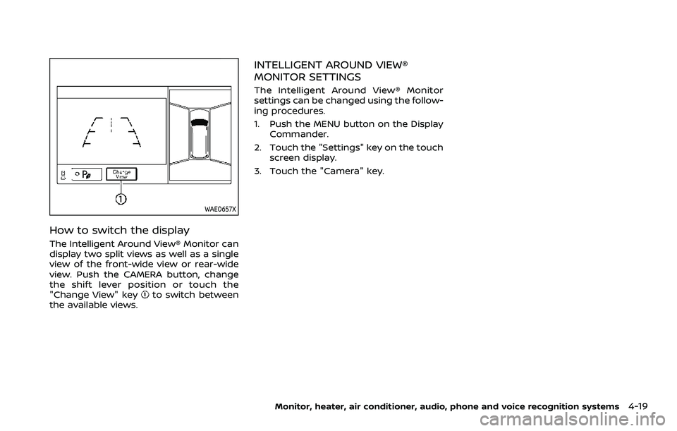
WAE0657X
How to switch the display
The Intelligent Around View® Monitor can
display two split views as well as a single
view of the front-wide view or rear-wide
view. Push the CAMERA button, change
the shift lever position or touch the
"Change View" key
to switch between
the available views.
INTELLIGENT AROUND VIEW®
MONITOR SETTINGS
The Intelligent Around View® Monitor
settings can be changed using the follow-
ing procedures.
1. Push the MENU button on the Display Commander.
2. Touch the "Settings" key on the touch screen display.
3. Touch the "Camera" key.
Monitor, heater, air conditioner, audio, phone and voice recognition systems4-19