2021 NISSAN ARMADA instrument panel
[x] Cancel search: instrument panelPage 194 of 603

3-12Pre-driving checks and adjustments
CAUTION
The lockout protection may not
function under the following condi-
tions:
.When the Intelligent Key is placed
on top of the instrument panel.
. When the Intelligent Key is placed
inside the glove box or a storage
bin.
. When the Intelligent Key is placed
inside the door pockets.
. When the Intelligent Key is placed
inside or near metallic materials.
Unlocking doors
1. Push the door handle request switch
(driver’s or front passenger’s)or the
liftgate request switchonce while
carrying the Intelligent Key with you.
When you approach the vehicle with
the Intelligent Key, the puddle light
and the passenger cabin illumination
will illuminate and stay on for a short
period of time (if so equipped). (See
“Welcome light” (P.2-77).)
2. The hazard indicator flashes once and outside chime sounds once. The cor-
responding door will unlock. 3. Push the door handle request switch
again within 60 seconds.
4. The hazard indicator flashes once and outside chime sounds once again. All
the doors will unlock.
The liftgate can be unlocked and opened
by pushing the liftgate opener switch. See
“Liftgate” (P.3-22).
All doors will be locked automatically
unless one of the following operations is
performed within 1 minute after pushing
the request switch while the doors are
locked. If during this 1-minute time period,
the request switch is pushed, all doors will
be locked automatically after another 1
minute.
. Opening any door
. Pushing the ignition switch
NOTE:
The unlocking operation can be chan-
ged in selective unlock in the Vehicle
Settings of the vehicle information dis-
play. See “Vehicle settings” (P.2-23).
Power liftgate open (if so equipped)
1. Carry the Intelligent Key.
2. Push the power liftgate opener switch
.
3. The liftgate will unlock and automati- cally open. 4. The hazard indicator flashes 4 times
and the outside chime sounds.
BATTERY SAVER SYSTEM
When all the following conditions are met
for a period of time, the battery saver
system will cut off the power supply to
prevent battery discharge.
.The ignition switch is in the ACC
position, and
. All doors are closed, and
. The shift lever is in the P (Park)
position.
WARNING SIGNALS
To help prevent the vehicle from moving
unexpectedly by erroneous operation of
the Intelligent Key listed on the following
chart or to help prevent the vehicle from
being stolen, chime or beep sounds inside
and outside the vehicle and a warning
displays in the vehicle information display.
When a chime or beep sounds or the
warning displays, be sure to check the
vehicle and Intelligent Key.
See “Troubleshooting guide” (P.3-13) and
“Vehicle information display” (P.2-19).
Page 203 of 603

.The remote engine startbutton is
not pushed and held within 5 seconds
of pushing the “LOCK”
button.
. The brake pedal is depressed.
. The doors are not closed and locked.
. The liftgate is open.
. The Key System Error warning light
remains on in the vehicle information
display.
. An Intelligent Key is left inside the
vehicle.
. The theft alarm sounds due to illegal
entry into the vehicle.
. Two remote engine starts, or a single
remote engine start with an exten-
sion, have already been used.
. The shift lever is not in the P (Park)
position.
The remote engine start may display a
warning or indicator in the vehicle infor-
mation display. For an explanation of the
warning or indicator, see “Operational
indicators” (P.2-29).
WAD0267X
1. Pull the hood lock release handlelocated below the instrument panel;
the hood will then spring up slightly.
2. Pull the lever
up at the front of the
hood with your fingertips and raise
the hood.
3. When closing the hood, slowly close the hood down and make sure it locks
into place.
WARNING
.Make sure the hood is completely
closed and latched before driving.
Failure to do so could cause the hood to fly open and result in an
accident.
. If you see steam or smoke com-
ing from the engine compart-
ment, to avoid injury do not
open the hood.
Pre-driving checks and adjustments3-21
HOOD
Page 205 of 603

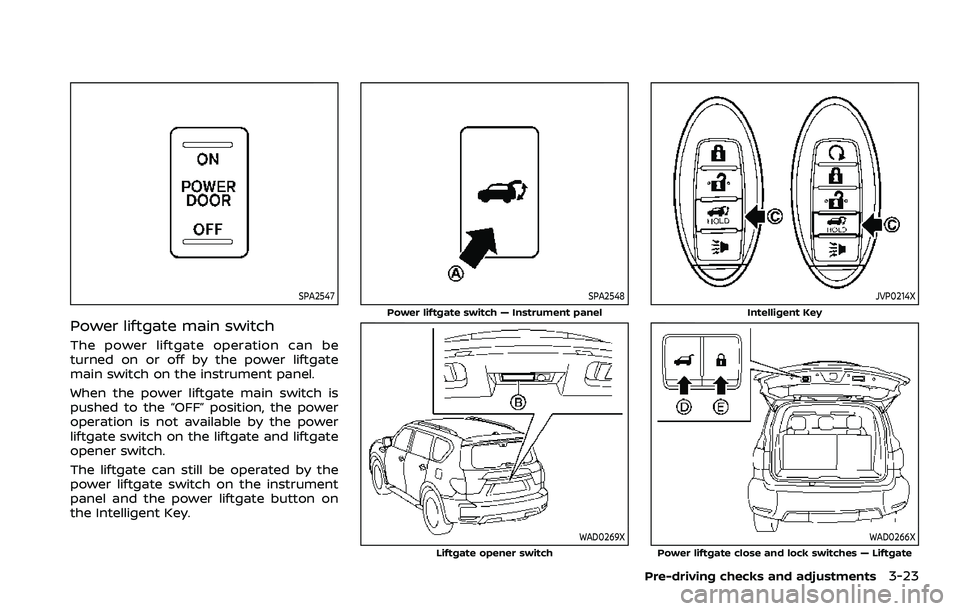
SPA2547
Power liftgate main switch
The power liftgate operation can be
turned on or off by the power liftgate
main switch on the instrument panel.
When the power liftgate main switch is
pushed to the “OFF” position, the power
operation is not available by the power
liftgate switch on the liftgate and liftgate
opener switch.
The liftgate can still be operated by the
power liftgate switch on the instrument
panel and the power liftgate button on
the Intelligent Key.
SPA2548
Power liftgate switch — Instrument panel
WAD0269XLiftgate opener switch
JVP0214X
Intelligent Key
WAD0266XPower liftgate close and lock switches — Liftgate
Pre-driving checks and adjustments3-23
Page 206 of 603

3-24Pre-driving checks and adjustments
Power open
When the liftgate is fully closed, the
liftgate will fully open automatically by:
.pushing the power liftgate switch
on the instrument panel
. pushing the liftgate opener switch
.pushing the power liftgate buttonon the Intelligent Key for more than 1
second
The hazard flashes 4 times and the out-
side chime sounds when the liftgate
starts opening.
NOTE:
The liftgate can be opened by the
power liftgate switch
, the liftgate
opener switchor the power liftgate
buttoneven if the liftgate is
locked. The liftgate will individually un-
lock and open.
Power close
When the liftgate is fully opened, the
liftgate will fully close automatically by:
. pushing the power liftgate switch
on the instrument panel
. pushing the power liftgate button
on the Intelligent Key for more than 1
second
. pushing the power liftgate close
switch
on the lower part of the
liftgate The hazard flashes 4 times and the out-
side chime sounds when the liftgate
starts closing.
NOTE:
When the liftgate is closed, it remains
unlocked. Manually lock the liftgate.
Power close and lock
When the liftgate is fully opened and the
Intelligent Key is carried with you near the
liftgate, the liftgate will fully close and lock
automatically by pushing the power lift-
gate lock switch
on the lower part of
the liftgate.
The hazard flashes 4 times and the out-
side chime sounds when the liftgate
starts closing.
Reverse function
The power liftgate will reverse immedi-
ately if one of the following actions is
performed during power open or power
close.
. pushing the power liftgate switch
on the instrument panel
. pushing the power liftgate button
on the Intelligent Key.
. pushing the power liftgate close
switch
on the lower part of the
liftgate
The outside chime sounds when the
liftgate starts to reverse.
Auto reverse function
The auto-reverse function enables the
liftgate to automatically reverse when
something is caught in the liftgate as it
is opening or closing. When the control
unit detects an obstacle, the liftgate will
reverse and return to the full open or full
close position.
If a second obstacle is detected, the
liftgate motion will stop and the drive
motor will disengage. The liftgate will
enter the manual mode.
A pinch sensor is mounted on each side
of the liftgate. If an obstacle is detected
by the pinch sensor during power close,
the liftgate will reverse and return to the
full open position immediately.
NOTE:
If the pinch sensor is damaged or
removed, the power close function will
not operate.
WARNING
There is a small distance immedi-
ately before the closed position that
cannot be detected. Make sure that
all passengers keep their hands, etc.,
clear from the liftgate opening be-
fore closing the liftgate.
Page 265 of 603

OPERATING TIPS
When the engine coolant temperature
and outside air temperature are low, the
air flow from the foot outlets may not
operate. However, this is not a malfunc-
tion. After the coolant temperature
warms up, the air flow from the foot
outlets will operate normally.
The sensors
andlocated on the
instrument panel help maintain a con-
stant temperature. Do not put anything
on or around the sensors.
LINKING INTELLIGENT KEY (if so
equipped)
The air conditioner system settings can
be memorized for each Intelligent Key.
For more details, see “Setting memory
function” (P.3-42).
IN-CABIN MICROFILTER
The air conditioner system is equipped
with an in-cabin microfilter which collects
dirt, pollen, dust, etc.
To make sure the air conditioner heats,
defogs, and ventilates efficiently, replace
the filter in accordance with the specified
maintenance intervals listed in the “9.
Maintenance and schedules” section. It is
recommended to see a NISSAN dealer to
replace the filter.
The filter should be replaced if the air flow decreases significantly or if win-
dows fog up easily when operating the
heater or air conditioner.
SERVICING AIR CONDITIONER
The air conditioner system in your NISSAN
is charged with a refrigerant designed
with the environment in mind.
This re-
frigerant will not harm the earth’s
ozone layer. However, special charging
equipment and lubricant are required
when servicing your NISSAN air condi-
tioner. Using improper refrigerants or
lubricants will cause severe damage to
your air conditioner system. (See “Capa-
cities and recommended fluids/lubri-
cants” (P.10-2) for air conditioner system
refrigerant and lubricant recommenda-
tions.)
Your NISSAN dealer will be able to service
your environmentally friendly air condi-
tioner system.
WARNING
The system contains refrigerant un-
der high pressure. To avoid personal
injury, any air conditioner service
should be done only by an experi-
enced technician with the proper
equipment.
WINDOW ANTENNA
The antenna pattern is printed inside the
rear side glass.
CAUTION
. Do not place metalized film near
the 3rd row seat window or at-
tach any metal parts to it. This
may cause poor reception or
noise.
. When cleaning the inside of the
rear side window, be careful not
to scratch or damage the rear
side window antenna. Lightly
wipe along the antenna with a
dampened soft cloth.
Monitor, heater, air conditioner, audio, phone and voice recognition systems4-41
ANTENNA
Page 297 of 603

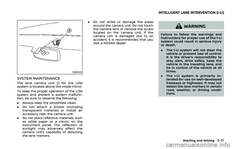
SSD0453
SYSTEM MAINTENANCE
The lane camera unitfor the LDW
system is located above the inside mirror.
To keep the proper operation of the LDW
system and prevent a system malfunc-
tion, be sure to observe the following:
. Always keep the windshield clean.
. Do not attach a sticker (including
transparent material) or install an
accessory near the camera unit.
. Do not place reflective materials, such
as white paper or a mirror, on the
instrument panel. The reflection of
sunlight may adversely affect the
camera unit’s capability of detecting
the lane markers. .
Do not strike or damage the areas
around the camera unit. Do not touch
the camera lens or remove the screw
located on the camera unit. If the
camera unit is damaged due to an
accident, it is recommended that you
visit a NISSAN dealer.
WARNING
Failure to follow the warnings and
instructions for proper use of the I-LI
system could result in serious injury
or death.
.The I-LI system will not steer the
vehicle or prevent loss of control.
It is the driver’s responsibility to
stay alert, drive safely, keep the
vehicle in the traveling lane, and
be in control of the vehicle at all
times.
. The I-LI system is primarily in-
tended for use on well-developed
freeways or highways. It may not
detect the lane markers in certain
road, weather, or driving condi-
tions.
Starting and driving5-31
INTELLIGENT LANE INTERVENTION (I-LI)
Page 303 of 603

SYSTEM MALFUNCTION
If the I-LI system malfunctions, it will
cancel automatically. The I-LI indicator
(orange) will illuminates and the “Malfunc-
tion” warning message will appear in the
vehicle information display.
If the I-LI indicator (orange) illuminates,
pull off the road to a safe location. Turn
the engine off and restart the engine. If
the I-LI indicator (orange) continues to
illuminate, have the I-LI system checked. It
is recommended that you visit a NISSAN
dealer for this service.
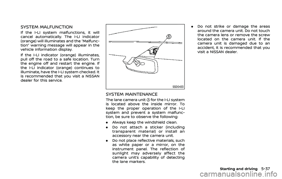
SSD0453
SYSTEM MAINTENANCE
The lane camera unitfor the I-LI system
is located above the inside mirror. To
keep the proper operation of the I-LI
system and prevent a system malfunc-
tion, be sure to observe the following:
. Always keep the windshield clean.
. Do not attach a sticker (including
transparent material) or install an
accessory near the camera unit.
. Do not place reflective materials, such
as white paper or a mirror, on the
instrument panel. The reflection of
sunlight may adversely affect the
camera unit’s capability of detecting
the lane markers. .
Do not strike or damage the areas
around the camera unit. Do not touch
the camera lens or remove the screw
located on the camera unit. If the
camera unit is damaged due to an
accident, it is recommended that you
visit a NISSAN dealer.
Starting and driving5-37
Page 321 of 603

.“Not Available: High Camera Temp”:
If the vehicle is parked in direct sun-
light under high temperature condi-
tions (over approximately 104°F
(40°C)).
. “Unavailable Side Radar Obstruction”:
When side radar blockage is detected.
Turn off the I-BSI system and turn it on
again when the above conditions no
longer exist.
SYSTEM MALFUNCTION
When the I-BSI system malfunctions, it will
be turned off automatically, the I-BSI
indicator illuminates and a chime will
sound, and the “Malfunction” warning
message will appear in the vehicle infor-
mation display.
Action to take:
Stop the vehicle in a safe location and
push the park button to engage the P
(Park) position. Turn the engine off and
restart the engine. If the warning mes-
sage continues to appear, It is recom-
mended you visit a NISSAN dealer for this
service.
WAF0769X
SYSTEM MAINTENANCE
The two radar sensorsfor the I-BSI
system are located near the rear bumper.
Always keep the area near the radar
sensors clean.
The radar sensors may be blocked by
temporary ambient conditions such as
splashing water, mist or fog.
The blocked condition may also be
caused by objects such as ice, frost or
dirt obstructing the radar sensors.
Check for and remove objects obstruct-
ing the area around the radar sensors.
Do not attach stickers (including trans-
parent material), install accessories or apply additional paint near the radar
sensors.
Do not strike or damage the area around
the radar sensors.
It is recommended you visit a NISSAN
dealer if the area around the radar
sensors is damaged due to a collision.
The lane camera unit
for I-BSI system is
located above the inside mirror. To keep
the proper operation of I-BSI and prevent
a system malfunction, be sure to observe
the following:
. Always keep the windshield clean.
. Do not attach a sticker (including
transparent material) or install an
accessory near the camera unit.
. Do not place reflective materials, such
as white paper or a mirror, on the
instrument panel. The reflection of
sunlight may adversely affect the
camera unit’s capability of detecting
the lane markers.
. Do not strike or damage the areas
around the camera unit. Do not touch
the camera lens or remove the screw
located on the camera unit. It is
recommended you contact a NISSAN
dealer if the camera unit is damaged
due to an accident.
Starting and driving5-55